EP0518269B1 - A process for making high calorie city gas - Google Patents
A process for making high calorie city gas Download PDFInfo
- Publication number
- EP0518269B1 EP0518269B1 EP92109709A EP92109709A EP0518269B1 EP 0518269 B1 EP0518269 B1 EP 0518269B1 EP 92109709 A EP92109709 A EP 92109709A EP 92109709 A EP92109709 A EP 92109709A EP 0518269 B1 EP0518269 B1 EP 0518269B1
- Authority
- EP
- European Patent Office
- Prior art keywords
- gas
- reaction
- heat
- column
- hydrogen
- Prior art date
- Legal status (The legal status is an assumption and is not a legal conclusion. Google has not performed a legal analysis and makes no representation as to the accuracy of the status listed.)
- Expired - Lifetime
Links
Images


Classifications
-
- C—CHEMISTRY; METALLURGY
- C10—PETROLEUM, GAS OR COKE INDUSTRIES; TECHNICAL GASES CONTAINING CARBON MONOXIDE; FUELS; LUBRICANTS; PEAT
- C10L—FUELS NOT OTHERWISE PROVIDED FOR; NATURAL GAS; SYNTHETIC NATURAL GAS OBTAINED BY PROCESSES NOT COVERED BY SUBCLASSES C10G OR C10K; LIQUIFIED PETROLEUM GAS; USE OF ADDITIVES TO FUELS OR FIRES; FIRE-LIGHTERS
- C10L3/00—Gaseous fuels; Natural gas; Synthetic natural gas obtained by processes not covered by subclass C10G, C10K; Liquefied petroleum gas
-
- C—CHEMISTRY; METALLURGY
- C10—PETROLEUM, GAS OR COKE INDUSTRIES; TECHNICAL GASES CONTAINING CARBON MONOXIDE; FUELS; LUBRICANTS; PEAT
- C10K—PURIFYING OR MODIFYING THE CHEMICAL COMPOSITION OF COMBUSTIBLE GASES CONTAINING CARBON MONOXIDE
- C10K3/00—Modifying the chemical composition of combustible gases containing carbon monoxide to produce an improved fuel, e.g. one of different calorific value, which may be free from carbon monoxide
Definitions
- This invention relates to a process for making high calorie city gas from hydrocarbonic crude materials such as butane, propane, naphtha and the like, and more particularly to an improvement in such a process.
- the system should have the following characteristics: (1) it should be easy to operate the starting, stoppage and load-change of the plant with high response; (2) the efficiency of gasification and gaseous quality should be high; and (3) it is essential that the plants should be able to operate in a simple manner and with high economic efficiency.
- the steps (1) to (5) are the processing steps of crude gas including the pretreatment step of crude gas; the middle two steps, i.e. the step (6) and step (7) are the refining steps of processed gas; and the last step, i.e. the step (8), is the carburetting step of the processed gas.
- the five steps comprising of: the five units of vessel or column to cover the first five steps above; two units of heating furnace; and one unit of recycle-gas compressor for the recycle gas containing some hydrogen to decarbonate is proposed.
- the five steps comprising of: the five units of vessel or column to cover the first five steps above; two units of heating furnace; and one unit of recycle-gas compressor for the recycle gas containing some hydrogen to decarbonate is proposed.
- it requires additional back-up systems such as another furnace which is used only during the start-up of the plant with heat-up bypass branched from the furnace; its incidental equipment and the like.
- the conventional systems are disadvantageous in that (1) their systems and their operation are relatively complex; (2) due to too many systems, they have a large amount of heat and energy losses, and (3) they lack economical efficiency because of the high cost of gas production.
- the load-change of the whole system is also a problem in that the response of the whole system to a load-change takes a long time, for example over one minute per one percent of load-change.
- the technical means provided by the present invention for achieving the objects described above is to provide a process including the following steps: the step of a methanizing reaction; the step of a desulfurizing reaction; the step of maintaining a predetermined temperature to meet with the reactive condition of activating a catalyst; the step of temperature control; and the step of introducing the heat from an external heat source by way of a heat transfer medium for enabling the transfer of heat between the catalyst and heat source.
- the present invention provides a simplification of the operation of refining SNG comprising the steps of producing, refining and carburetting the elementary feed gas.
- the process of the present invention improves the efficiency of gasification, to reduce the cost of gas production, and to enable the operation of the start-up, stoppage and load-change of the whole system within fifteen minutes.
- the hydrocarbonic crude materials such as butane, propane, naphtha and the like are pressurized to around a reaction pressure by a crude material pump (1), and then subsequently heated up and vaporized by a crude material preheater (2) and a crude material evaporator (3).
- the materials are mixed with a hydrogen-rich mixture gas produced in a reaction column (8) in a crude materials/hydrogen mixer (4), and the temperature of the crude material/hydrogen mixture gas is controlled in a crude material superheater (5) to be about 350°C and then sent into an integral type desulfurizing column (6) which is operated to activate and adsorb the sulfureous contents of the crude material/hydrogen mixture gas.
- the sulfureous content in the desulfurizing column (6) is reduced to hydrogen sulfide (H2S) by the hydrogen additive reaction between the hydrogen and inert sulfureous compounds of the crude material gas through the nimox catalyst bed filled in the outward passage tubes within the desulfurizing column (6).
- H2S hydrogen sulfide
- the hydrogen sulfide (H2S) now contained within the crude material gas reacts when it reaches the zinc oxide bed in the return passage tubes in the manner H2S+ZnO -> ZnS+H2.
- the ZnS is adsorbed by an adsorbent ZnO so that the sulfureous content is removed from the crude material/hydrogen mixture gas.
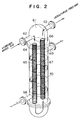
- Figure 2 illustrates that the desulfurizing column (6) is in the form of a shell and tube type heat exchanger having fixed tubes with baffle plates (70) therein.
- the interior of the upper chamber includes a flange and is vertically sub-divided by a partition plate (61) which forms a U-shaped passage with the inlet (62) of the hydrogen-mixed feed gas and also the outlet (63) of the desulfurized hydrogen-mixed feed gas.
- the inlet (62) communicates with the outward passage (64) filled with the nimox catalyst (65), the outlet (63) communicates with the return passage (66) filled with the zinc oxide (67).
- the heat transfer medium previously heated in a heat medium furnace (7) to about 350°C is forcedly flowed upwardly within the shell side in a zig-zag stream due to the plurality of baffle plates (70) to maintain the catalysts at an activating temperature.
- the heat transfer medium is flowed into the column (6) through an inlet (68) and out of the column through an outlet (69).
- the heat transfer medium has a large heat capacity, and is forcedly flowed in turn from the heat medium furnace (7), to the crude material superheater (5) and then to the desulfurizing column (6) to constantly keep them at a predetermined temperature.
- This temperature control of the feed gas and catalyst by the heat transfer medium is not only useful in the regular operation of the system but also useful during start-up and load-change.
- the heat transfer medium is one of the major reasons that the system of this invention can undergo rapid start-up and respond quickly to load-change.
- the temperature difference between the hydrogen-mixed feed gas and the catalysts was difficult to control because the heating was carried out by an internal heating system operated by the heat of the gas. This control was particularly difficult in the start-up stage of the system. In the worst case, this resulted in the catalyst causing the problem of carbonic extraction in a high temperature zone, and reversely causing insufficient desulfurization in a low temperature zone.
- the present invention solves this disadvantage of prior art devices by providing the external heating means (7) for the heat medium.
- the prior art devices used two units of column separately for each catalyst.
- the present invention provides an integral unit column having a minimized surface as illustrated in Fig. 2. This arrangement makes it possible to minimize heat loss through radiation from the desulfurizing device which favourably influences the total plant efficiency.
- Desulfurized hydrogen-mixed feed gas is delivered from the desulfurizing column (6) and is mixed with steam in the feed gas/steam mixer (9) to produce a desulfurized feed gas/steam mixture gas.
- This gas mixture is heated up to a reaction temperature of approximately 320°C in the feed gas superheater (10).
- the mixture is then fed into the steam-reforming column (8) in which the feed gas is reacted in an isothermal reforming (i.e. thermal cracking) reaction and also methanizing reaction under specific reaction conditions.
- This reaction is carried out using a catalyst having a large activation such as an alumina group carrier supported by nickel.
- the resulting single pass reaction is carried out at high speed within only a one unit column in which a high calorie type fuel gas rich in CH4 and less CO is reformed.
- the hydrocarbon is thermally cracked by steam on the catalyst and CO and H2 are formed in accordance with the following chemical equation: C4H10 + 4H2O ⁇ 4CO + 9H2
- the hydrocarbon causes the methanation reaction and shift reaction on CO and H2, and the following synthetic reaction is further progressed: (CO + H2O ⁇ CO2 + H2) (CO + 3H2 ⁇ CH4 + H2O) (CO2 + 4H2 ⁇ CH4 + 2H2O)
- the above synthetic reaction can be carried out in a one unit column with a single pass reaction.
- the combined use type methanation column (8) comprises a shell and tube type heat exchanger having fixed tubes with baffle plates therein.
- the fixed tubes, i.e. the reaction tubes (81), are filled with methanizing catalyst (82), and the heat transfer medium having a temperature of approximately 320°C is forcedly flowed upward from the heat medium inlet (83) positioned at the lower portion into the space between the shell drum and reaction tubes (81) through the heat medium shunt/control valve (11) [ Figure 1] to heat and maintain the catalyst at its effective operating temperature.
- this relationship is controlled by the heat transfer medium having a large heat capacity which is forcedly flowed in order through the heat medium shunt/control valve (11), the column (8) and the feed gas/steam superheater (10) to maintain them at a constant predetermined temperature.
- This temperature control of the feed gas and catalyst by the heat transfer medium is not only useful in the regular operation of the system but also useful during start-up and load-change of the system.
- the heat transfer medium is one of the major reasons that this system can undergo rapid start-up and respond quickly to load-change as well as the case of the desulfurizing column (6) described previously.
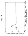
- Figure 4 illustrates the relationship between the temperature of the catalyst bed (82) in the combined use type methanation column (8) between the steam-reforming reaction zone (i.e. endothermic reaction) and methanizing reaction zone (i.e. exothermic reaction), and the depth of the catalyst bed.
- the temperature is determined by a plurality of thermal sensors within the bed.
- Figure 4 illustrates that the catalyst-temperature slightly descends initially and then suddenly increases up to around 360°C in the shallow portion of the bed. This indicates that the beginning of the catalytic reaction occurs near the entrance. This temperature variation is believed to occur due to an endothermic reaction in the steam-reforming zone causing the temperature to dip followed by an exothermic reaction in the methanizing reaction zone causing the temperature to rise to about 360°C.
- the temperature again descends suddenly from the peak of about 360°C, and is stabilized at about 320°C which corresponds with the temperature of the heat transfer medium of about 320°C.
- the peak catalyst temperature is rapidly cooled due to the flow of fresh heat transfer medium introduced from the heat medium inlet (83).
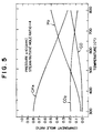
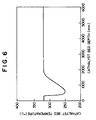
- This is positioned at the lower portion of the reaction column (8) and adopts a counter-flow type heat exchanging method. Consequently the product gas, i.e. the methane-rich gas and also the elementary feed gas, which is produced by the reaction column (8) is sufficiently cooled by the fresh flow of the heat transfer medium so that a relatively high yield of CH4 can be expected in a lower temperature zone as illustrated in Figure 5.
- Figure 5 shows that the lower the temperature, the higher the yield of CH4. It is theoretically known that the gas composition described above has a thermodynamically equilibrium composition. Therefore, the gas composition can be obtained by theoretical calculation.
- the heat transfer medium flows upwards through baffle plates (84) and absorbs heat from the reaction tubes generated in the exothermic reaction zone.
- the heat transfer medium then flows into the endothermic zone where it releases its heat to the reaction tubes to heat up the tubes.
- the heat medium then flows out from the upper portion of the column (8) through outlet (87). This means that the heat transfer medium is heated up in the exothermic reaction zone and the heat transfer medium releases its heat in the endothermic reaction zone after the temperature of the heat transfer medium reaches its peak.
- the heat transfer in the endothermic reaction zone is performed at high speed due to the wide temperature difference. This results in the acceleration of the endothermic reaction.
- the process of the present invention makes use of a one unit column with a single pass reaction as described above because the heat transfer medium can momently absorb a large amount of heat generated in the exothermic reaction zone.
- Conventional systems make use of a two or three unit column system due to the failure of their heat transfer system to efficiently absorb generated heat.
- the present invention succeeds in solving the multiplied reaction problem of the prior art by providing a simplified reaction device with minimized radiation surface which is energy efficient as described in connection with the desulfurizing column (8).
- the present invention gains a small amount of highly concentrated hydrogen for use in the hydrodesulfurization by hydrogenizing the methanol/water mixture to be fed into the hydrogenizing column (8) as described previously. This improves the overall efficiency of the plant and also facilitates start-up and the ability of the system to react to load-change.
- methanol is pressurized to about a reactive pressure by a methanol pump (12), and then mixed with degassified water in a methanol/water mixer (13).
- the resulting solution is vaporized in a methanol evaporator (14) by heating the methanol/water mixture.
- the vaporized methanol/water mixture gas is further heated in a methanol superheater (15) to approximately 320°C after which the superheated methanol/water mixture gas is fed into the reaction column (8).
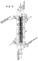
- reaction column (8) is of the combined use type, i.e. two system reaction tubes are mounted within a single unit shell drum.
- One reaction system mounted in the column is used for the steam-reforming and methanation and the other reaction system is used for hydrogenization which will now be explained in detail.
- FIG 3 schematically illustrates that a partial tube (86) of the plurality of reaction tubes is filled with a hydrogenizing catalyst (85) and used as the hydrogenizing reaction tube (86).
- the methanol/water mixture having the same temperature as the steam-reforming reaction temperature is fed into the hydrogenizing reaction tube (86).
- the methanol/water mixture undergoes an isothermal reaction on the hydrogenizing catalyst (85) under specific reactive conditions in a high speed single pass reaction, in which the methanol/water mixture is converted into a hydrogen-rich mixture gas which is relatively rich in H2 and depleted in CO and CH4 (i.e. CH3OH + H2O -> 3H2 + CO2).
- the tube (86) is disposed along the center axis line of the column (8) so as to pass through both chambers in the upper and lower portions and this tube is filled with hydrogenizing catalyst (85).
- the temperature control, the advantage in the start-up and load-change and the like of tube (86) these are generally the same as in the methanizing reaction tube (81).
- the present invention can reduce radiation heat loss due to the large size of the first column described above, the energy loss consumed by the recycle gas compressor and the double energy loss consumed to cool the recycle gas before the desulfurization and again to heat up the processed gas after the desulfurization.
- the present invention only consumes a small amount of energy to power the methanol pump (12), and has minimal radiation heat-loss from the integral type column (8) in addition to the highly efficient process of producing the highly concentrated hydrogen from the methanol with the high speed start-up and load-change capabilities of the plant.
- the combination of the hydrodesulfurization and steam-reforming are significant to the present invention. These significant reactions are achieved by maintaining each catalyst at an optimum operating temperature and also by providing the feed gases, i.e. the hydrogen-mixed feed gas, steam-mixed feed gas and methanol/water mixture gas, at an optimum temperature by supplying these from the external heat source through the inorganic salt type heat transfer medium.
- This heat transfer medium has sometimes been called "heat transfer salt” (i.e. HTS) in the art.
- HTS is a eutectic mixture selected from sodium nitrite, sodium nitrate and potassium nitrate.
- the advantage of this HTS is that its coefficient of heat transfer is more than 50% higher than oil group heat transfer mediums which are generally used in the art at temperatures of less than 350°C if it is required to operate a rapid heat transfer, e.g. a reaction temperature between 320°C and 350°C used in the present invention, when it is required to transfer heat from the heat transfer medium to a reaction column and/or the interior of a shell drum of a heat exchanger for removing and/or supplying the heat from or to the reaction tubes therein.
- a rapid heat transfer e.g. a reaction temperature between 320°C and 350°C used in the present invention
- HTS in the present system is delivered and pressurized from a heat medium reservoir (16) by a heat medium pump (17) and then the flow of HTS is branched into two streams, i.e. into the desulfurization system and steam-reforming system through a three-way control valve (11).
- the flow of HTS is heated up to 352°C by the heat medium furnace (7) in order to control the desulfurizing temperature at 350°C as described previously, and then the flow of HTS supplies the heat itself to or reversely absorbs (i.e. in the desulfurizing column only) the heat from each of the inner tubes of respective heat exchanging devices while passing through the shell drum of the crude material superheater (5), desulfurizing column (6), and a secondary water-supply heater (23). Finally the temperature of the HTS drops to about 321°C and is returned into the heat medium reservoir (16).
- the flow of HTS is branched by the three-way control valve (11) and heated up to a temperature of reforming of about 320°C, and then the flow of HTS supplies the heat itself to or reversely absorbs (i.e. in the desulfurizing column only) the heat from each of the inner tubes of the respective heat exchanging devices while passing through the shell drum of the reaction column (8), feed gas/steam superheater (10), crude materials evaporator (3) and methanol superheater (15). Finally the temperature of the HTS drops to about 321°C and is returned to the heat medium reservoir (16).
- the temperature of each branched flow is controlled by controlling the flow rate of each branched flow through the three-way control valve (11).
- reaction heat-device group i.e. reaction column or desulfurizing device
- heat recovery device group i.e. evaporator, superheater and the like
- heating device group i.e. heat medium furnace
- the temperature control of the heat medium furnace (7) it is controlled by controlling the fuel rate in response to the inlet-temperature of the heat transfer medium flow into the desulfurizing column.
- the heat balance of the whole system can be sensitively controlled by the furnace (7).
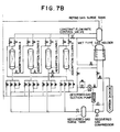
- Figure 7 illustrates a preferred practical example of an arrangement for making high calorie type city gas according to the present invention.
- the composition and characteristics of each gas stream number shown in Figure 7 is set out in Table 1 below.
- a butane evaporator (27) is provided in the arrangement illustrated in Figure 7 for carburetting the product gas according to the present invention.
- the present invention provides the following advantages:
Landscapes
- Chemical & Material Sciences (AREA)
- Engineering & Computer Science (AREA)
- Oil, Petroleum & Natural Gas (AREA)
- Combustion & Propulsion (AREA)
- Chemical Kinetics & Catalysis (AREA)
- General Chemical & Material Sciences (AREA)
- Organic Chemistry (AREA)
- Organic Low-Molecular-Weight Compounds And Preparation Thereof (AREA)
- Hydrogen, Water And Hydrids (AREA)
- Catalysts (AREA)
- Superconductors And Manufacturing Methods Therefor (AREA)
Applications Claiming Priority (2)
| Application Number | Priority Date | Filing Date | Title |
|---|---|---|---|
| JP142903/91 | 1991-06-14 | ||
| JP3142903A JPH0686598B2 (ja) | 1991-06-14 | 1991-06-14 | 高熱量都市ガスの製造方法 |
Publications (3)
| Publication Number | Publication Date |
|---|---|
| EP0518269A2 EP0518269A2 (en) | 1992-12-16 |
| EP0518269A3 EP0518269A3 (en) | 1993-05-12 |
| EP0518269B1 true EP0518269B1 (en) | 1995-08-30 |
Family
ID=15326291
Family Applications (1)
| Application Number | Title | Priority Date | Filing Date |
|---|---|---|---|
| EP92109709A Expired - Lifetime EP0518269B1 (en) | 1991-06-14 | 1992-06-10 | A process for making high calorie city gas |
Country Status (7)
| Country | Link |
|---|---|
| EP (1) | EP0518269B1 (enExample) |
| JP (1) | JPH0686598B2 (enExample) |
| KR (1) | KR930000658A (enExample) |
| CN (1) | CN1068357A (enExample) |
| AT (1) | ATE127146T1 (enExample) |
| DE (1) | DE69204361T2 (enExample) |
| TW (1) | TW197467B (enExample) |
Families Citing this family (8)
| Publication number | Priority date | Publication date | Assignee | Title |
|---|---|---|---|---|
| AU6799996A (en) * | 1996-05-29 | 1997-12-04 | Sunkyong Industries Co., Ltd. | Gaseous compositions containing a bittering agent |
| FR2788839B1 (fr) | 1999-01-22 | 2001-04-20 | Saint Gobain Vitrage | Procede et dispositif de regulation d'un courant de combustible gazeux |
| CN103865585A (zh) * | 2008-09-19 | 2014-06-18 | 格雷特波因特能源公司 | 碳质原料的气化装置 |
| CN102583593B (zh) * | 2012-02-21 | 2015-12-16 | 北京纬纶华业环保科技股份有限公司 | 一种处理高浓度有机废水生产甲烷气体的方法与装置 |
| CN106560505A (zh) * | 2015-09-25 | 2017-04-12 | 新地能源工程技术有限公司 | 一种依靠低温甲醇溶液脱除合成天然气中水的工艺及装置 |
| JP6707049B2 (ja) * | 2017-03-23 | 2020-06-10 | 大阪瓦斯株式会社 | 燃料ガス製造装置の運転方法 |
| MX2022013183A (es) * | 2020-04-27 | 2022-11-14 | Gencell Ltd | Proceso para la descomposicion termica de amoniaco y reactor para llevar a cabo el proceso. |
| CN114110736B (zh) * | 2021-11-25 | 2023-02-28 | 广西电网有限责任公司电力科学研究院 | 一种不同汽温抽汽非接触式换热供汽方法 |
Family Cites Families (3)
| Publication number | Priority date | Publication date | Assignee | Title |
|---|---|---|---|---|
| GB1544245A (en) * | 1976-05-21 | 1979-04-19 | British Gas Corp | Production of substitute natural gas |
| NL7908283A (nl) * | 1979-11-13 | 1981-06-01 | Veg Gasinstituut Nv | Werkwijze voor de produktie van synthetisch aardgas uit koolwaterstoffen. |
| GB2154600A (en) * | 1984-02-23 | 1985-09-11 | British Gas Corp | Producing and purifying methane |
-
1991
- 1991-06-14 JP JP3142903A patent/JPH0686598B2/ja not_active Expired - Lifetime
-
1992
- 1992-04-21 TW TW081103098A patent/TW197467B/zh active
- 1992-06-08 KR KR1019920009888A patent/KR930000658A/ko not_active Withdrawn
- 1992-06-10 DE DE69204361T patent/DE69204361T2/de not_active Expired - Fee Related
- 1992-06-10 EP EP92109709A patent/EP0518269B1/en not_active Expired - Lifetime
- 1992-06-10 AT AT92109709T patent/ATE127146T1/de not_active IP Right Cessation
- 1992-06-11 CN CN92104519A patent/CN1068357A/zh active Pending
Also Published As
| Publication number | Publication date |
|---|---|
| EP0518269A3 (en) | 1993-05-12 |
| ATE127146T1 (de) | 1995-09-15 |
| JPH04366200A (ja) | 1992-12-18 |
| DE69204361T2 (de) | 1996-03-21 |
| CN1068357A (zh) | 1993-01-27 |
| DE69204361D1 (de) | 1995-10-05 |
| KR930000658A (ko) | 1993-01-15 |
| TW197467B (enExample) | 1993-01-01 |
| JPH0686598B2 (ja) | 1994-11-02 |
| EP0518269A2 (en) | 1992-12-16 |
Similar Documents
| Publication | Publication Date | Title |
|---|---|---|
| US4162290A (en) | Parallel steam reformers to provide low energy process | |
| US4079017A (en) | Parallel steam reformers to provide low energy process | |
| US4865624A (en) | Method for steam reforming methanol and a system therefor | |
| US5512599A (en) | Process for the production of methanol | |
| AU742314B2 (en) | Steam reforming | |
| US5496530A (en) | Process for the preparation of carbon monoxide rich gas | |
| Adris et al. | On the reported attempts to radically improve the performance of the steam methane reforming reactor | |
| US3388074A (en) | Two-stage steam reforming with rapid warm-up in first stage by means of a promoted catalyst | |
| AU2011234159B2 (en) | Hydrogen/syngas generator | |
| US5300275A (en) | Steam reforming | |
| US3264066A (en) | Production of hydrogen | |
| US3642460A (en) | Process for the production of a methane-containing gas | |
| EA006869B1 (ru) | Получение углеводородов | |
| US7192569B2 (en) | Hydrogen generation with efficient byproduct recycle | |
| US4224298A (en) | Reforming of hydrocarbons | |
| US20110085967A1 (en) | Hydrogen product method and apparatus | |
| EP1277721A2 (en) | Method of manufacturing methanol | |
| US3625665A (en) | Process for the production of methane containing gases | |
| US3551124A (en) | Process of gasifying hydrocarbon fractions containing sulfur | |
| EP0518269B1 (en) | A process for making high calorie city gas | |
| GB2585478A (en) | Process for synthesising methanol | |
| NO335117B1 (no) | Fremgangsmåte for fremstilling av hydrokarboner ved Fischer-Tropsch reaksjon | |
| US3975169A (en) | Process for producing a natural gas substitute | |
| JPS6148810B2 (enExample) | ||
| EP0295715B1 (en) | Process for forming city gas with high heat value from methanol as a crude material |
Legal Events
| Date | Code | Title | Description |
|---|---|---|---|
| PUAI | Public reference made under article 153(3) epc to a published international application that has entered the european phase |
Free format text: ORIGINAL CODE: 0009012 |
|
| AK | Designated contracting states |
Kind code of ref document: A2 Designated state(s): AT BE CH DE DK ES FR GB GR IT LI LU MC NL PT SE |
|
| PUAL | Search report despatched |
Free format text: ORIGINAL CODE: 0009013 |
|
| AK | Designated contracting states |
Kind code of ref document: A3 Designated state(s): AT BE CH DE DK ES FR GB GR IT LI LU MC NL PT SE |
|
| 17P | Request for examination filed |
Effective date: 19930618 |
|
| 17Q | First examination report despatched |
Effective date: 19940422 |
|
| GRAA | (expected) grant |
Free format text: ORIGINAL CODE: 0009210 |
|
| AK | Designated contracting states |
Kind code of ref document: B1 Designated state(s): AT BE CH DE DK ES FR GB GR IT LI LU MC NL PT SE |
|
| PG25 | Lapsed in a contracting state [announced via postgrant information from national office to epo] |
Ref country code: NL Free format text: LAPSE BECAUSE OF FAILURE TO SUBMIT A TRANSLATION OF THE DESCRIPTION OR TO PAY THE FEE WITHIN THE PRESCRIBED TIME-LIMIT Effective date: 19950830 Ref country code: MC Free format text: LAPSE BECAUSE OF NON-PAYMENT OF DUE FEES Effective date: 19950830 Ref country code: LI Effective date: 19950830 Ref country code: GR Free format text: LAPSE BECAUSE OF FAILURE TO SUBMIT A TRANSLATION OF THE DESCRIPTION OR TO PAY THE FEE WITHIN THE PRESCRIBED TIME-LIMIT Effective date: 19950830 Ref country code: ES Free format text: THE PATENT HAS BEEN ANNULLED BY A DECISION OF A NATIONAL AUTHORITY Effective date: 19950830 Ref country code: DK Effective date: 19950830 Ref country code: CH Effective date: 19950830 Ref country code: BE Effective date: 19950830 Ref country code: AT Effective date: 19950830 |
|
| REF | Corresponds to: |
Ref document number: 127146 Country of ref document: AT Date of ref document: 19950915 Kind code of ref document: T |
|
| ET | Fr: translation filed | ||
| REF | Corresponds to: |
Ref document number: 69204361 Country of ref document: DE Date of ref document: 19951005 |
|
| REG | Reference to a national code |
Ref country code: CH Ref legal event code: PL |
|
| ITF | It: translation for a ep patent filed | ||
| PG25 | Lapsed in a contracting state [announced via postgrant information from national office to epo] |
Ref country code: SE Effective date: 19951130 Ref country code: PT Effective date: 19951130 |
|
| NLV1 | Nl: lapsed or annulled due to failure to fulfill the requirements of art. 29p and 29m of the patents act | ||
| PGFP | Annual fee paid to national office [announced via postgrant information from national office to epo] |
Ref country code: GB Payment date: 19960606 Year of fee payment: 5 |
|
| PGFP | Annual fee paid to national office [announced via postgrant information from national office to epo] |
Ref country code: FR Payment date: 19960627 Year of fee payment: 5 |
|
| PG25 | Lapsed in a contracting state [announced via postgrant information from national office to epo] |
Ref country code: LU Free format text: LAPSE BECAUSE OF NON-PAYMENT OF DUE FEES Effective date: 19960630 |
|
| PLBE | No opposition filed within time limit |
Free format text: ORIGINAL CODE: 0009261 |
|
| STAA | Information on the status of an ep patent application or granted ep patent |
Free format text: STATUS: NO OPPOSITION FILED WITHIN TIME LIMIT |
|
| PGFP | Annual fee paid to national office [announced via postgrant information from national office to epo] |
Ref country code: DE Payment date: 19960729 Year of fee payment: 5 |
|
| 26N | No opposition filed | ||
| PG25 | Lapsed in a contracting state [announced via postgrant information from national office to epo] |
Ref country code: GB Free format text: LAPSE BECAUSE OF NON-PAYMENT OF DUE FEES Effective date: 19970610 |
|
| GBPC | Gb: european patent ceased through non-payment of renewal fee |
Effective date: 19970610 |
|
| PG25 | Lapsed in a contracting state [announced via postgrant information from national office to epo] |
Ref country code: FR Free format text: LAPSE BECAUSE OF NON-PAYMENT OF DUE FEES Effective date: 19980227 |
|
| PG25 | Lapsed in a contracting state [announced via postgrant information from national office to epo] |
Ref country code: DE Free format text: LAPSE BECAUSE OF NON-PAYMENT OF DUE FEES Effective date: 19980303 |
|
| REG | Reference to a national code |
Ref country code: FR Ref legal event code: ST |
|
| REG | Reference to a national code |
Ref country code: FR Ref legal event code: ST |
|
| PG25 | Lapsed in a contracting state [announced via postgrant information from national office to epo] |
Ref country code: IT Free format text: LAPSE BECAUSE OF NON-PAYMENT OF DUE FEES;WARNING: LAPSES OF ITALIAN PATENTS WITH EFFECTIVE DATE BEFORE 2007 MAY HAVE OCCURRED AT ANY TIME BEFORE 2007. THE CORRECT EFFECTIVE DATE MAY BE DIFFERENT FROM THE ONE RECORDED. Effective date: 20050610 |