EP0517409A1 - Optisches System aus refraktiven und diffraktiven optischen Elementen zur Korrektur chromatischer Aberrationen - Google Patents
Optisches System aus refraktiven und diffraktiven optischen Elementen zur Korrektur chromatischer Aberrationen Download PDFInfo
- Publication number
- EP0517409A1 EP0517409A1 EP92304722A EP92304722A EP0517409A1 EP 0517409 A1 EP0517409 A1 EP 0517409A1 EP 92304722 A EP92304722 A EP 92304722A EP 92304722 A EP92304722 A EP 92304722A EP 0517409 A1 EP0517409 A1 EP 0517409A1
- Authority
- EP
- European Patent Office
- Prior art keywords
- optical
- lens group
- diffractive
- elements
- refractive
- Prior art date
- Legal status (The legal status is an assumption and is not a legal conclusion. Google has not performed a legal analysis and makes no representation as to the accuracy of the status listed.)
- Granted
Links
Images


Classifications
-
- G—PHYSICS
- G02—OPTICS
- G02B—OPTICAL ELEMENTS, SYSTEMS OR APPARATUS
- G02B5/00—Optical elements other than lenses
- G02B5/18—Diffraction gratings
- G02B5/1876—Diffractive Fresnel lenses; Zone plates; Kinoforms
-
- G—PHYSICS
- G02—OPTICS
- G02B—OPTICAL ELEMENTS, SYSTEMS OR APPARATUS
- G02B27/00—Optical systems or apparatus not provided for by any of the groups G02B1/00 - G02B26/00, G02B30/00
- G02B27/0025—Optical systems or apparatus not provided for by any of the groups G02B1/00 - G02B26/00, G02B30/00 for optical correction, e.g. distorsion, aberration
Definitions
- optical systems suffer from image aberrations.
- the ultimate quality and performance of an optical system is determined by the extent to which aberrations, particularly chromatic aberrations, are corrected.
- significant improvement is achieved over the prior art by minimizing chromatic aberrations. Additional advantages are obtained by reducing the number of optical elements needed to achieve equivalent or superior results.
- the present invention relates generally to improved structure for assemblies of optical systems in which refractive and diffractive optical elements are combined advantageously to achieve significant improvement in chromatic aberration.
- the diverse characteristic properties of these two types of optical elements are cancelled out by suitably opposing and balancing these properties against each other to achieve hitherto unobtainable image quality.
- achromatic lens assemblies have been employed with limited success since the time of Isaac Newton.
- two optical elements one with positive power and one with negative power
- conventional glass materials e.g. crown and flint glass
- Ever increasing sophistication with both methods and materials has been applied to the fundamental problem or correcting chromatic aberration, and powerful computational methods combined with development of special glass materials have achieved significant improvement. It is typical of such effort, however, that ever smaller incremental gains are achieved at continually increasing cost.
- Reference 1 is a paper by Gary. J. Swanson and Wilfred. B. Veldcamp, SPIE Poceedings, Vol. 885, Paper #22, 1988. They propose using binary optics to correct axial chromatic aberration.
- binary optics the functional effect of a grating is achieved with grooves that are etched with typical fabrication processes employed in microelectronics.
- Their system has serious deficiencies, because as numerical aperture increases, marked spherochromatism is exhibited. Consequently, the minimum useable f-number is severly limited. This limitation is particularly unfortunate in advanced infrared optical systems that require low f-numbers (typically f/1.0 to f/1.5) to help reduce size and weight.
- the present invention has many important and novel features. Many deficiencies of the prior art are substantially reduced or eliminated, such as those associated with f-number and field of view. Several kinds of chromatic aberration are corrected including axial primary, axial secondary, lateral primary, and lateral secondary. Correction is provided for all orders of spherochromatism, chromatic coma, and chromatic distortion. In the spectral intervals between the three selected design wavelengths, residual chromatic aberrations are significantly reduced.
- the use of this invention will improve significantly the image quality of optical systems including both refractive and catadioptric types and will apply over wavelengths ranging from the ultraviolet to the infrared.
- the structure disclosed for axial chromatic aberration, axial secondary color, and spherochromatism is well suited for telephoto lens systems.
- the structure that is disclosed to correct lateral chromatic aberration, secondary lateral color, chromatic distortion and chromatic coma is particularly effective for optical systems employing external pupils.
- the structure disclosed for correcting field curvature without aggravating lateral chromatic aberration is particularly useful for optical systems with wide fields of view and for systems employing Petzval type lenses.
- Examples of typical wavelength response will demonstrate the value of forming optical structures employing this invention.
- Chromatic aberrations result from the varying characteristic response as a function of wavelength for the optical element.
- An important example is the variation of focal length along the central axis.
- EFL effective focal length
- a typical glass-diffractive achromat exhibits a maximum value near its central wavelength region of operation.
- these characteristic aberrations of opposite algebraic sense can be matched so that they essentially cancel each other to reduce overall chromatic aberration in the complete lens structure.
- the special optical glasses that are eliminated have at least two disadvantages: they are more expensive and have substantially less resistance to damage from radiation.
- Figure 1 illustrates a typical conventional achromatic lens (glass-refractive) employing an assembly or structure of two refractive optical elements.
- a positive element of crown glass and a negative element of flint glass are employed.
- Figure 2 illustrates a typical glass-diffractive achromat whose use is important to this invention.
- the assembly or structure consists of a conventional refractive optical element or lens made of either flint or crown glass, upon at least one surface of which a diffractive element (e.g. grating or Fresnel zone plate) has been applied, attached, or formed.
- a diffractive element e.g. grating or Fresnel zone plate
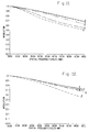
- FIG 3 shows typical curves of effective focal length (EFL) as a function of wavelength for two basic optical structures of the types illustrated in Figures 1 and 2.
- the upper curve is for a glass-refractive achromat; the lower curve is for a glass-diffractive achromat.
- Figure 4 is a general schematic diagram representing two typical optical structures for an eyepiece lens. Structures are shown for both a conventional lens and a comparable lens employing the principles of the present invention.
- Figure 5 is a general schematic diagram representing two typical optical structures for a Petzval lens, which in this example has an internal pupil. Both a conventional lens and an equivalent lens employing the present invention are shown.
- Figure 6 is a general schematic diagram representing two typical optical structures for a lens with an external pupil and with a large aperture. Both a conventional lens and a comparable lens employing the principles of the present invention are shown.
- Figure 7 is a general schematic diagram representing two typical optical structures for a telephoto lens. Structures are shown for both a conventional lens and an equivalent lens employing the principles of the present invention.
- Figure 8 illustrates two typical well designed optical structures for a Petzval lens with an external pupil.
- Figure 8a is a conventional structure with 10 refractive optical elements.
- Figure 8b is a comparable glass-diffractive structure requiring six refractive optical elements plus two diffractive elements.
- Figure 9 shows the H tan U optical performance curves for the conventional glass-refractive lens shown in Figure 8a.
- Figure 10 shows the H tan U optical performance curves for the comparable glass-diffractive lens shown in Figure 8b.
- FIG 11 shows the MTF performance curves for the conventional all-glass lens shown in Figure 8a.
- Figure 12 shows the MTF performance curves for the glass-diffractive lens shown in Figure 8b.
- Figure 13 shows a glass-diffractive structure for a Petzval lens similar to that of Figure 8b, but with a reduced f-number of f/2.5. Six refractive elements plus two diffractive elements are required.
- Figure 14 shows the H tan U optical performance curves for the glass-diffractive lens shown in Figure 13.
- chromatic aberrational effects include primary axial color, primary lateral color, secondary axial color, and secondary lateral color.
- primary correction proper correction is achieved at only two specific design wavelengths within the operating spectral interval.
- secondary correction proper correction is achieved at three specific design wavelengths.
- Aberrations for primary axial color and primary lateral color are usually corrected through the use of either cemented or air-spaced achromats.
- achromatic optical assemblies with perfect correction at three selected design wavelengths.
- conventional glass achromats are replaced with apochromats, which are expensive.
- An apochromat consists of at least two refractive optical elements, at least one of which is made of special optical glass.
- more refractive optical elements are inserted into the system to reduce the optical power demanded of each individual element.
- An additional advantage of the combined glass-diffractive lens structure is that optical power demanded from each individual optical element of the achromat is reduced but in a manner different from that employed in the prior art with glass-refractive structures, i.e. not by merely introducing more refractive elements.
- optical power required from individual elements can be reduced because in a glass-diffractive achromat only elements (both refractive and diffractive) with positive optical power are needed; whereas in an glass-refractive achromatic lens both positive and negative elements must be employed.
- structures employing glass-diffractive elements as prescribed by this invention achieve significant improvement in Petzval curvature, higher order spacial aberrations, and higher order chromatic aberrations.
- a further application of this invention is to employ glass-diffractive elements to correct for primary lateral color.
- a glass-diffractive element with a very small amount of primary axial chromatic aberration near the image plane a significant amount of beneficial primary lateral chromatic aberration will be introduced as a result of the large ratio of chief ray height to marginal ray height.
- a chief ray lies at the edge of the image; the marginal ray lies at the center of the image.
- a conventional glass doublet performs a similar function, its use generally upsets the correction for the Petzval curvature and introduces higher order aberrations.
- An additional advantage of this invention is the use of combinations of glass-diffractive elements to correct for chromatic distortion. Such correction is related to the approach just described for introducing beneficial primary lateral chromatic aberration. If a corrective higher order (i.e. third order and higher order) aspherical wavefront is encoded in the diffractive portion of the glass-diffractive element described above, chromatic distortions of all orders can be corrected simultaneously. Such encoding is achieved, for example, by varying appropriately the spacing between lines of a Fresnel zone plate as a function of radius.
- Figure 1 shows a conventional glass-refractive achromat with two elements. It consists of an assembly of a crown glass element 2 with positive optical power and a flint glass element 4 with negative optical power.
- Figure 2 shows a comparable glass-diffractive achromat assembled with a conventional refractive element 6 of positive optical power and a diffractive element 8 also with positive optical power applied to or formed upon the refractive element. It is important to note that typical diffractive elements are extremely thin and occupy virtually zero space in optical structures that employ them.
- FIG 3 illustrates some significant differences in performance of these two achromats involving the effective focal length (EFL) that is exploited to great advantage in this invention. It is seen in this figure that EFLs as a function of wavelength for (a) a typical refractive glass achromat and (b) for a typical glass-diffractive achromat are of significantly different shape. Although the vertical scale is greatly expanded, Figure 3 shows that for a typical glass-refractive achromat, minimum EFL occurs in the central wavelength region, while at the outer wavelengths EFLs are longer. For the glass-diffractive achromat, maximum EFL occurs in the central wavelength region, while shorter EFLs pertain in the outer wavelength regions.
- EFLs effective focal length
- Abbe number is defined as (N2 - 1)/(N1 - N3).
- the N values refer to index of refraction associated with corresponding wavelengths having increasing values: L1, L2, and L3. Because the Abbe number for any kind of glass is always positive, EFLs for central wavelengths over the spectral range of a glass achromat must be shorter than those for outer wavelengths. It follows that secondary axial chromatic aberration cannot be corrected properly using a series of different glass achromats.
- the novel method employed in this invention for correcting chromatic aberration is to utilize the opposite algebraic sense previously established in this disclosure for the secondary axial chromatic aberrations of these two different types of achromats.
- both primary axial and secondary axial chromatic aberrations can be corrected simultaneously.
- Figure 4 illustrates two general schematic diagrams for eyepiece lenses.
- Figure 4a shows a typical eyepiece employing conventional construction.
- Figure 4b shows a comparable eyepiece lens that employs the principles of this invention.
- lens group 10 contains a plurality of refractive elements with positive optical power overall.
- Eye 13 is located near aperture stop 14 at the left end of optical axis 11; image 12 being viewed by the eye is shown at the far end of the optical axis at the right.
- lens group 16 with positive optical power contains at least one refractive optical element and at least one diffractive optical element.
- diffractive element 17 is placed between the third and fourth refractive elements of lens group 16. It is understood that detailed arrangements and locations of optical elements within lens group 16 other than those described in this example are consistent with the spirit of this invention.
- Eye 19 and aperture stop 18 are located in a fashion similar to that shown in Figure 4a. Image 20 being viewed by the eye is shown at the far end of optical axis 15.
- schematic diagram Figure 4b the significantly smaller size of the structure obtained employing the principles of this invention is evident when compared to the corresponding conventional structure.
- lateral color, distortion, chromatic distortion, and field curvature are easily corrected by employing a single diffractive optical element.
- the structure contains fewer refractive optical elements, and is more compact than that of Figure 4a. Further, eye relief is long, and field of view is large.
- Figure 5 illustrates two general schematic diagrams for Petzval lenses that in this example contain an internal aperture stop (also called a pupil). Each of these structures employs three lens groups.
- Figure 5a shows a typical conventional structure for a Petzval lens;
- Figure 5b shows a comparable structure employing the principles of this invention.
- input lens group 21, located at the left end of optical axis 23, contains refractive elements with positive overall optical power.
- At least one element (shown in this example as 22) of lens group 21 is made of special optical glass.
- Aperture stop 24 is located to the right of lens group 21.
- Lens group 26 to the right of the aperture stop consists of refractive optical elements with positive overall optical power.
- At least one refractive element (shown in this example as the third element from the left 28) in lens group 26 is made of special optical glass.
- the last optical element on the right end of the optical axis is field lens 30.
- Image 32 is formed at the far right end of the optical axis.
- Figure 5b shows an equivalent typical structure for a Petzval lens employing the principles of this invention.
- Input lens group 40 at the left end of optical axis 41 contains retractive elements with overall positive optical power.
- Internal aperture stop 42 is located to the right of lens group 40.
- Lens group 44 to the right of the aperture stop in this figure contains refractive optical elements and at least one diffractive optical element. It is within the spirit of this invention to include alternatively at least one diffractive element in either lens group 40 or lens group 44, or to employ diffractive elements in both lens groups.
- the overall optical power of lens group 44 is positive.
- one element of lens group D shown as the right-most element 46
- Field lens group 48 lies next to the right along the optical axis and contains refractive elements and at least one diffractive optical element.
- one element of the field lens group shown as element 50 on the right
- Image 51 is formed to the right of field lens group 48.
- Figure 6 illustrates two general schematic diagrams for large aperture lenses with an external pupil. Each of these structures employs three lens groups.
- Figure 6a shows a conventional structure
- Figure 6b shows a comparable structure employing the principles of this invention.
- input aperture stop 52 is at the left end of optical axis 53.
- lens group 54 that contains refractive optical elements with positive overall optical power. At least one element in lens group 54 is made of special optical glass. In this example, lens group 54 contains four refractive elements, and the third element from the left 56 in lens group 54 is made of special optical glass. In actual practice of the prior art, other arrangements and locations of such refractive optical elements employed throughout this typical structure need not affect the illustrative value of this example.
- lens group 58 Next along the optical axis to the left is lens group 58 that contains refractive optical elements having positive overall optical power. At least one element in lens group 58 will be made of special optical glass.
- the third element from the left 60 in lens group 58 is made of special optical glass.
- the field lens group 62 is the last on the right and contains refractive elements.
- the field lens group contains one element.
- Image 64 is formed at the right end of the optical axis.
- Figure 6b shows a comparable optical structure for a typical large aperture lens with an external pupil employing the principles of this invention.
- External aperture stop 66 is at the left of the optical axis 67.
- lens group 68 that may contain both refractive and diffractive elements.
- lens group 68 contains only refractive optical elements with overall positive optical power.
- lens group 70 that contains both refractive and diffractive optical elements with overall positive optical power.
- the right-most element 72 of lens group 70 is diffractive. It is understood that detailed arrangements and locations of individual optical elements within lens groups 68 and 70 other than those described in this example are consistent with the spirit of this invention.
- Field lens group 74 is at the right end of the optical axis and contains refractive and diffractive optical elements.
- right element 76 is diffractive.
- Image 80 is formed to the right of the field lens group at the right end of the optical axis.
- Figure 7 includes general schematic diagrams for two telephoto lenses that contain an internal aperture stop. Each of these structures employs two lens groups.
- Figure 7a shows a typical conventional structure
- Figure 7b shows a comparable structure employing the principles of this invention.
- input lens group 82 at the left end of optical axis 83 contains refractive elements.
- the central element 84 of three is made of special optical glass.
- aperture stop 86 Next to the right is aperture stop 86.
- Lens group 88 to the right of the aperture stop has overall negative optical power and contains refractive elements.
- third element 90 from the left (out of four elements) is made of special optical glass.
- Image 92 is formed at the right end of the optical axis.
- Figure 7b shows a typical equivalent structure for a telephoto lens that employs the principles of this invention.
- Input lens group 94 has positive overall optical power and in the figure is located at the left end of optical axis 95. This lens group may contain both refractive and diffractive elements.
- Next along the optical axis is the aperture stop 96.
- Lens group 98 next to the right has negative optical power and may contain both refractive and diffractive optical elements. In the example of Figure 7b, two elements are refractive, and the third 100 on the right is diffractive. It is understood that detailed arrangements and locations of such refractive and diffractive optical elements within lens group 98 other than those described in this example are consistent with the spirit of this invention.
- Image 102 is formed at the right end of the optical axis.
- Comparison of the two telephoto lens structures in Figure 7 demonstrates substantial advantages obtained from the use of this invention.
- the glass-diffractive structure of Figure 7b is smaller and lighter because fewer optical elements are required. No special optical glass is employed. Spherochromatism and secondary color can be corrected simultaneously through the use of diffractive optical elements in lens group 94, lens group 98, or both. Aperture size is larger than that obtainable in the conventional structure of Figure 7a.
- Figure 8 shows two fully designed optical structures, each for a representative Petzval lens with an external pupil. This example was chosen because while an external pupil is mechanically convenient, it also involves a more difficult optical design. Both structures have the same f-number (f/3.2), the same EFL (3 inches), and the same field of view (10 degrees).
- Figure 8a shows a well designed Petzval lens structure with conventional refractive optical elements.
- Figure 8b shows a comparable structure employing the principles of this invention.
- entrance pupil 104 is followed by lens group 106 having overall positive optical power and containing three refractive elements.
- the central optical element 108 of this group is made of type KZFSN4 special optical glass.
- lens group 110 with overall positive optical power and containing five retractive optical elements.
- the fourth element from the left 112 of this group also is made of type KZSFN4 special optical glass.
- field lens group 114 contains two refractive elements. Ten optical elements are required in this glass-retractive assembly using conventional construction from the prior art.
- Image 115 is formed to the right of lens group 114.
- Figure 8b illustrates a comparable structure employing the principles of this invention.
- lens group 118 that contains two refractive elements.
- lens group 120 that contains three refractive elements plus one diffractive element 122 formed or applied on the left-most refractive element 121.
- field lens group 124 contains one refractive element 125 plus diffractive element 126 applied to or formed upon the right surface of refractive element 125.
- Image 127 is formed to the right of lens group 124.
- FIG. 8a Comparison between the conventional optical assembly of Figure 8a and that of Figure 8b, which employs the priciples of this invention, demonstrates substantial advantages over the prior art in actual workable optical structures.
- the conventional assembly or Figure 8a contains a total of ten refractive elements including two made of special optical glass.
- the assembly of Figure 8b contains only six refractive elements (none of which requires special optical glass) plus two diffractive elements, which occupy virtually no space.
- Figures 9 and 10 are employed to analyze and compare the two well-designed structures shown in Figure 8 by means of H tan U optical performance curves. These curves, which are commonly used by those skilled in the art to analyze optical designs, show the tangential and sagittal aberrations along two designated axes.
- Figure 9 shows the H tan U curves for the all glass structure of Figure 8a. The optical performance of this design would be considered excellent in the prior art.
- Designations DY and DX refer to the geometric aberrations along the Y and X directions, respectively. Symbols 1, 2, and 3 respectively indicate curves for wavelengths of the d-line, F-line, and C-line.
- Horizontal axes Y REF and X REF are, respectively, the pupil coordinates along the Y and X axes.
- Conditions and associated locations for the six groups of curves shown in Figure 9 are given in Table 1.
- Figure 10 shows corresponding H tan U curves for the glass-diffraction structure of Figure 8b.
- the axes, symbols, conditions, designations, and locations are same as described for Figure 9 and as shown in Table 1.
- the glass-diffraction design is clearly superior for all criteria of optical performance indicated by the H tan U curves.
- these comparative analyses with H tan U curves demonstrate the further advantages of this invention over the prior art.
- Figures 11 and 12 compare the two structures of Figure 8 on the basis of modulation transfer function (MTF) out to 100 cycles per mm.
- MTF curves show the degradation of modulation with increasing spatial frequency and are an additional basis for evaluating optical performance.
- Figure 11 shows typical MTF curves for the all glass structure of Figure 8a. Such performance would be considered excellent in the prior art.
- Letter notations are employed on the curves in Figure 11 to indicate type of geometric aberration and field of view; particular meanings of the letters are given in Table 2.
- Figure 12 shows corresponding MTF curves for the glass-diffractive structure of Figure 8b.
- Letter notations for the curves in Figure 12 are the same as those given in Table 2. Modulation is substantially better for the glass-diffraction structure at all spatial frequencies. On the basis of the MTF criterion, additional advantages in superior performance obtained from the use of this invention are evident.
- Figure 13 illustrates an optical structure that is similar to the glass-diffraction structure of Figure 8b but for which f-number has been reduced from f/3.2 to f/2.5. This greatly improved specification provides an additional basis of comparison between the optical performance of the typical all glass structure of Figure 8a with that obtained from the use of this invention, as will be shown.
- Entrance pupil 128 is shown at the left of Figure 13.
- Lens group 129 with positive overall optical power contains two refractive elements.
- Lens group 130 with overall positive optical power contains three refracrive elements plus a diffractive element 132 applied or formed on the left-most diffractive element 131.
- Field lens group 134 contains one refractive element 135 plus a diffractive element 136 applied or attached to element 135.
- Image 137 is formed to the right of lens group 134.
- Figure 14 shows H tan U performance curves for the glass-diffractive structure of Figure 13.
- Figure 14 the axes, symbols, conditons, designations, and locations are the same as described for Figure 9 and as shown in Table 1. Comparing Figure 14 with Figure 10 shows the expected degradation of optical performance that reflects the significant burden of reducing the f-number from f/3.2 to f/2.5. Comparing Figure 14 with Figure 9, however, provides further indication of the superiority of this invention.
- These H tan U curves demonstrate that optical performance of the f/2.5 glass-diffraction structure of Figure 13 is still superior to the comparable f/3.2 glass-refractive structure of Figure 8a.
Landscapes
- Physics & Mathematics (AREA)
- General Physics & Mathematics (AREA)
- Optics & Photonics (AREA)
- Lenses (AREA)
- Diffracting Gratings Or Hologram Optical Elements (AREA)
Applications Claiming Priority (2)
| Application Number | Priority Date | Filing Date | Title |
|---|---|---|---|
| US710859 | 1985-03-12 | ||
| US07/710,859 US5148314A (en) | 1991-06-06 | 1991-06-06 | Optical systems employing refractive and diffractive optical elements to correct for chromatic aberration |
Publications (2)
| Publication Number | Publication Date |
|---|---|
| EP0517409A1 true EP0517409A1 (de) | 1992-12-09 |
| EP0517409B1 EP0517409B1 (de) | 1997-10-01 |
Family
ID=24855840
Family Applications (1)
| Application Number | Title | Priority Date | Filing Date |
|---|---|---|---|
| EP92304722A Expired - Lifetime EP0517409B1 (de) | 1991-06-06 | 1992-05-26 | Optisches System aus refraktiven und diffraktiven optischen Elementen zur Korrektur chromatischer Aberrationen |
Country Status (6)
| Country | Link |
|---|---|
| US (1) | US5148314A (de) |
| EP (1) | EP0517409B1 (de) |
| JP (1) | JPH05157963A (de) |
| DE (1) | DE69222466T2 (de) |
| ES (1) | ES2108088T3 (de) |
| IL (1) | IL101666A (de) |
Cited By (4)
| Publication number | Priority date | Publication date | Assignee | Title |
|---|---|---|---|---|
| EP0840144A1 (de) * | 1996-10-29 | 1998-05-06 | Canon Kabushiki Kaisha | Linsensystem mit einer diffractiven und einer refractiven Oberfläche und eine dieses Linsensystem verwendende Vorrichtung |
| WO2000049449A1 (en) * | 1999-02-16 | 2000-08-24 | Intel Corporation | Lens system for photodetectors |
| EP1129370A1 (de) * | 1998-11-12 | 2001-09-05 | U.S. Precision Lens Inc. | Farbkorrigierte projektionslinsen mit verwendung von diffraktiven optischen oberflächen |
| WO2002084363A1 (en) * | 2001-04-12 | 2002-10-24 | Raytheon Company | External pupil lens system |
Families Citing this family (52)
| Publication number | Priority date | Publication date | Assignee | Title |
|---|---|---|---|---|
| US5268790A (en) * | 1991-12-20 | 1993-12-07 | Hughes Aircraft Company | Zoom lens employing refractive and diffractive optical elements |
| DE69325607T2 (de) * | 1992-04-07 | 2000-04-06 | Raytheon Co | Breites spektrales Band virtuelles Bildanzeige optisches System |
| DE4323971C2 (de) * | 1992-07-16 | 2002-11-07 | Asahi Optical Co Ltd | Schreib-/Lesegerät für eine optische Speicherplatte |
| DE69331020T2 (de) * | 1992-08-07 | 2002-06-06 | Matsushita Electric Ind Co Ltd | Optische Speichervorrichtung |
| US5737125A (en) * | 1992-10-27 | 1998-04-07 | Olympus Optical Co., Ltd. | Diffractive optical element and optical system including the same |
| US5349471A (en) * | 1993-02-16 | 1994-09-20 | The University Of Rochester | Hybrid refractive/diffractive achromatic lens for optical data storage systems |
| US5483362A (en) * | 1994-05-17 | 1996-01-09 | Environmental Research Institute Of Michigan | Compact holographic sight |
| US5815936A (en) * | 1994-05-17 | 1998-10-06 | Environmental Research Institute Of Michigan | Detachable hologram assembly and windage/elevation adjuster for a compact holographic sight |
| US5526185A (en) * | 1994-06-03 | 1996-06-11 | Xerox Corporation | Method and system for designing color corrected optical systems |
| US5623473A (en) * | 1994-06-30 | 1997-04-22 | Nikon Corporation | Method and apparatus for manufacturing a diffraction grating zone plate |
| US5446588A (en) * | 1994-07-29 | 1995-08-29 | The University Of Rochester | Wide-angle eyepiece optical system employing refractive and diffractive optical elements |
| US5548439A (en) * | 1994-12-27 | 1996-08-20 | Hughes Aircraft Company | Three field of view refractive infrared telescope with fixed medium filed of view |
| US5737120A (en) * | 1995-03-14 | 1998-04-07 | Corning Incorporated | Low weight, achromatic, athermal, long wave infrared objective lens |
| US5742431A (en) * | 1995-03-30 | 1998-04-21 | Eastman Kodak Company | Catadioptric lens system incorporating diffractive achromatization |
| US5818632A (en) * | 1995-04-13 | 1998-10-06 | Melles Griot, Inc | Multi-element lens system |
| JPH08286113A (ja) * | 1995-04-17 | 1996-11-01 | Olympus Optical Co Ltd | 対物レンズ |
| US5933283A (en) * | 1996-04-15 | 1999-08-03 | Canon Kabushiki Kaisha | Zoom lens |
| US5978145A (en) * | 1996-04-16 | 1999-11-02 | Minolta Co., Ltd. | Viewfinder optical system |
| US6052234A (en) * | 1996-04-16 | 2000-04-18 | Minolta Co., Ltd. | Viewfinder optical system |
| US6157498A (en) | 1996-06-19 | 2000-12-05 | Nikon Corporation | Dual-imaging optical system |
| JP3833754B2 (ja) * | 1996-07-02 | 2006-10-18 | オリンパス株式会社 | 回折型光学素子を有する電子カメラ |
| US6483638B1 (en) * | 1996-07-22 | 2002-11-19 | Kla-Tencor Corporation | Ultra-broadband UV microscope imaging system with wide range zoom capability |
| US5966244A (en) * | 1996-10-03 | 1999-10-12 | Minolta Co., Ltd. | Viewfinder optical system |
| JPH10115777A (ja) * | 1996-10-11 | 1998-05-06 | Olympus Optical Co Ltd | 撮影レンズ |
| US6101035A (en) * | 1996-10-24 | 2000-08-08 | Asahi Kogaku Kogyo Kabushiki Kaisha | Triplet lens system with diffractive lens features |
| US5973827A (en) * | 1997-03-27 | 1999-10-26 | Raytheon Company | Refractive/diffractive infrared imager and optics |
| US6070980A (en) * | 1997-04-08 | 2000-06-06 | Asahi Kogaku Kogyo Kabushiki Kaisha | Spectacle lens |
| JP3691638B2 (ja) * | 1997-07-03 | 2005-09-07 | オリンパス株式会社 | ズームレンズ及びそれを用いたカメラ |
| JPH1164726A (ja) * | 1997-08-22 | 1999-03-05 | Olympus Optical Co Ltd | 広角レンズ |
| US5880879A (en) * | 1997-08-26 | 1999-03-09 | Nikon Corporation | Objective lens system utilizing diffractive optical element |
| US6704149B2 (en) | 1998-04-21 | 2004-03-09 | Minolta Co., Ltd. | Lens optical system |
| US7295387B1 (en) | 1998-04-21 | 2007-11-13 | Minolta Co., Ltd. | Lens optical system |
| US6349004B1 (en) | 1999-07-16 | 2002-02-19 | Optics 1, Inc. | Head mounted display viewing optics with improved optical performance |
| JP2001108811A (ja) * | 1999-10-12 | 2001-04-20 | Canon Inc | 回折光学素子及び該回折光学素子を有する光学系 |
| KR100405660B1 (ko) * | 2001-10-10 | 2003-11-14 | 엘지전자 주식회사 | 텔레포토 형태의 회절광학계 |
| US6515801B1 (en) | 2001-12-21 | 2003-02-04 | Koninklijke Philips Electronics N.V. | Lateral color compensation for projection displays |
| US6980365B2 (en) * | 2003-03-05 | 2005-12-27 | 3M Innovative Properties Company | Diffractive lens optical design |
| JP2004361730A (ja) * | 2003-06-05 | 2004-12-24 | Yoshiharu Mizoguchi | 万華鏡 |
| JP2005070124A (ja) * | 2003-08-27 | 2005-03-17 | Canon Inc | 光走査装置及びそれを用いた画像形成装置 |
| US7038863B2 (en) | 2004-06-02 | 2006-05-02 | Raytheon Company | Compact, wide-field-of-view imaging optical system |
| JP5629050B2 (ja) | 2004-06-10 | 2014-11-19 | カール・ツァイス・エスエムティー・ゲーエムベーハー | マイクロリソグラフィ投影露光装置のための投影対物レンズ |
| EP1746463A2 (de) | 2005-07-01 | 2007-01-24 | Carl Zeiss SMT AG | Verfahren zum Korrigieren eines lithographischen Projektionsobjektivs und derartiges Projektionsobjektiv |
| DE102005054183A1 (de) * | 2005-11-14 | 2007-05-16 | Zeiss Carl Ag | HMD-Vorrichtung |
| EP2171517A4 (de) * | 2007-07-31 | 2012-02-29 | Battelle Energy Alliance Llc | Sichtoptik und verfahren zum sichten |
| EP2233959B1 (de) * | 2007-12-20 | 2016-11-16 | Nikon Corporation | Okularsystem und optische anordnung |
| JP5038963B2 (ja) * | 2008-04-11 | 2012-10-03 | 株式会社日立製作所 | 分光光学系および分光測定装置 |
| US8279520B2 (en) | 2010-07-30 | 2012-10-02 | Raytheon Company | Wide field of view LWIR high speed imager |
| EP2944919B1 (de) * | 2014-05-13 | 2020-01-22 | Leica Geosystems AG | Geodätisches gerät mit diffraktiven optischen elementen |
| AU2016209100B2 (en) * | 2015-01-22 | 2021-05-20 | Magic Leap, Inc. | Methods and system for creating focal planes using an alvarez lens |
| EP3489734B1 (de) * | 2016-07-07 | 2020-11-11 | Nikon Corporation | Okulares optisches system und am kopf montierte anzeige |
| JP7086709B2 (ja) | 2018-05-14 | 2022-06-20 | キヤノン株式会社 | 光学系およびそれを有する撮像装置 |
| US20230067508A1 (en) * | 2021-08-31 | 2023-03-02 | Zebra Technologies Corporation | Telephoto Lens for Compact Long Range Barcode Reader |
Citations (4)
| Publication number | Priority date | Publication date | Assignee | Title |
|---|---|---|---|---|
| DE3421705A1 (de) * | 1984-06-12 | 1986-04-24 | Ingolf Dr. 3300 Braunschweig Weingärtner | Abtastobjektiv mit einem hologramm |
| EP0359179A2 (de) * | 1988-09-12 | 1990-03-21 | Kenneth C. Johnson | Dispersionskompensierendes Diffraktionsgitter |
| EP0367241A2 (de) * | 1988-10-31 | 1990-05-09 | The University Of Rochester | Optisches Linsenabbildungssystem mittels Beugung |
| EP0441206A1 (de) * | 1990-02-06 | 1991-08-14 | Hughes Aircraft Company | Optisches Element mit asphärischen und binär beugenden optischen Oberflächen |
Family Cites Families (3)
| Publication number | Priority date | Publication date | Assignee | Title |
|---|---|---|---|---|
| JPH079501B2 (ja) * | 1986-12-18 | 1995-02-01 | 富士通株式会社 | グレ−テイングレンズ系 |
| JPH01319725A (ja) * | 1988-06-22 | 1989-12-26 | Canon Inc | 変倍ファインダー光学系 |
| JPH0356901A (ja) * | 1989-07-26 | 1991-03-12 | Canon Inc | グレーティングレンズ系 |
-
1991
- 1991-06-06 US US07/710,859 patent/US5148314A/en not_active Expired - Lifetime
-
1992
- 1992-04-21 IL IL10166692A patent/IL101666A/en not_active IP Right Cessation
- 1992-05-26 DE DE69222466T patent/DE69222466T2/de not_active Expired - Lifetime
- 1992-05-26 ES ES92304722T patent/ES2108088T3/es not_active Expired - Lifetime
- 1992-05-26 EP EP92304722A patent/EP0517409B1/de not_active Expired - Lifetime
- 1992-06-08 JP JP4147643A patent/JPH05157963A/ja active Pending
Patent Citations (4)
| Publication number | Priority date | Publication date | Assignee | Title |
|---|---|---|---|---|
| DE3421705A1 (de) * | 1984-06-12 | 1986-04-24 | Ingolf Dr. 3300 Braunschweig Weingärtner | Abtastobjektiv mit einem hologramm |
| EP0359179A2 (de) * | 1988-09-12 | 1990-03-21 | Kenneth C. Johnson | Dispersionskompensierendes Diffraktionsgitter |
| EP0367241A2 (de) * | 1988-10-31 | 1990-05-09 | The University Of Rochester | Optisches Linsenabbildungssystem mittels Beugung |
| EP0441206A1 (de) * | 1990-02-06 | 1991-08-14 | Hughes Aircraft Company | Optisches Element mit asphärischen und binär beugenden optischen Oberflächen |
Cited By (9)
| Publication number | Priority date | Publication date | Assignee | Title |
|---|---|---|---|---|
| EP0840144A1 (de) * | 1996-10-29 | 1998-05-06 | Canon Kabushiki Kaisha | Linsensystem mit einer diffractiven und einer refractiven Oberfläche und eine dieses Linsensystem verwendende Vorrichtung |
| US6590708B2 (en) | 1996-10-29 | 2003-07-08 | Canon Kabushiki Kaisha | Lens system having diffracting surface and refracting surface and optical apparatus using the lens system |
| EP1129370A1 (de) * | 1998-11-12 | 2001-09-05 | U.S. Precision Lens Inc. | Farbkorrigierte projektionslinsen mit verwendung von diffraktiven optischen oberflächen |
| EP1129370A4 (de) * | 1998-11-12 | 2002-07-24 | U S Prec Lens Inc | Farbkorrigierte projektionslinsen mit verwendung von diffraktiven optischen oberflächen |
| US6529336B1 (en) | 1998-11-12 | 2003-03-04 | U.S. Precision Lens Incorporated | Color corrected projection lenses employing diffractive optical surfaces |
| US6150653A (en) * | 1998-11-25 | 2000-11-21 | Intel Corporation | Lens system for photodetectors |
| WO2000049449A1 (en) * | 1999-02-16 | 2000-08-24 | Intel Corporation | Lens system for photodetectors |
| WO2002084363A1 (en) * | 2001-04-12 | 2002-10-24 | Raytheon Company | External pupil lens system |
| US6563654B2 (en) | 2001-04-12 | 2003-05-13 | Raytheon Company | External pupil lens system |
Also Published As
| Publication number | Publication date |
|---|---|
| DE69222466T2 (de) | 1998-05-07 |
| JPH05157963A (ja) | 1993-06-25 |
| IL101666A0 (en) | 1992-12-30 |
| IL101666A (en) | 1994-06-24 |
| DE69222466D1 (de) | 1997-11-06 |
| EP0517409B1 (de) | 1997-10-01 |
| US5148314A (en) | 1992-09-15 |
| ES2108088T3 (es) | 1997-12-16 |
Similar Documents
| Publication | Publication Date | Title |
|---|---|---|
| EP0517409B1 (de) | Optisches System aus refraktiven und diffraktiven optischen Elementen zur Korrektur chromatischer Aberrationen | |
| US5446588A (en) | Wide-angle eyepiece optical system employing refractive and diffractive optical elements | |
| US4545652A (en) | Flat field lenses | |
| US6366405B2 (en) | Diffractive-refractive achromatic lens | |
| US5808808A (en) | Wide-angle lens system | |
| IL103044A (en) | Optical eyepiece system of binoculars that uses refractive and diffused optical components | |
| GB2144874A (en) | Catadioptric lens | |
| US20060007559A1 (en) | Zoom lens system | |
| US5046833A (en) | Zoom lens system | |
| JPH1123968A (ja) | 回折面を有するズームレンズ | |
| US6268969B1 (en) | Image forming optical system having diffractive optical element | |
| US6147815A (en) | Imaging optical system | |
| US4953957A (en) | Zoom lens system | |
| US4730905A (en) | Eyepiece having a radial gradient index lens | |
| US5959785A (en) | Achromatic lens system including a diffraction lens | |
| US5381269A (en) | Zoom lens | |
| US4792216A (en) | Photographic lens system | |
| US4929071A (en) | Long-focus color-corrected petzval-type optical objective | |
| JPS614012A (ja) | 結像レンズ | |
| US3958866A (en) | Copying objective lens system | |
| US6011655A (en) | Eyepiece | |
| EP1377864B1 (de) | Externes pupillenlinsensystem | |
| US5790313A (en) | Eyepiece system | |
| US5080473A (en) | Vari-focal lens system | |
| US4331391A (en) | Lens system having wide angle objectives |
Legal Events
| Date | Code | Title | Description |
|---|---|---|---|
| PUAI | Public reference made under article 153(3) epc to a published international application that has entered the european phase |
Free format text: ORIGINAL CODE: 0009012 |
|
| AK | Designated contracting states |
Kind code of ref document: A1 Designated state(s): DE ES FR GB |
|
| 17P | Request for examination filed |
Effective date: 19930518 |
|
| 17Q | First examination report despatched |
Effective date: 19941219 |
|
| GRAG | Despatch of communication of intention to grant |
Free format text: ORIGINAL CODE: EPIDOS AGRA |
|
| GRAH | Despatch of communication of intention to grant a patent |
Free format text: ORIGINAL CODE: EPIDOS IGRA |
|
| GRAH | Despatch of communication of intention to grant a patent |
Free format text: ORIGINAL CODE: EPIDOS IGRA |
|
| GRAA | (expected) grant |
Free format text: ORIGINAL CODE: 0009210 |
|
| AK | Designated contracting states |
Kind code of ref document: B1 Designated state(s): DE ES FR GB |
|
| REF | Corresponds to: |
Ref document number: 69222466 Country of ref document: DE Date of ref document: 19971106 |
|
| ET | Fr: translation filed | ||
| REG | Reference to a national code |
Ref country code: ES Ref legal event code: FG2A Ref document number: 2108088 Country of ref document: ES Kind code of ref document: T3 |
|
| PLBE | No opposition filed within time limit |
Free format text: ORIGINAL CODE: 0009261 |
|
| STAA | Information on the status of an ep patent application or granted ep patent |
Free format text: STATUS: NO OPPOSITION FILED WITHIN TIME LIMIT |
|
| 26N | No opposition filed | ||
| REG | Reference to a national code |
Ref country code: GB Ref legal event code: 732E |
|
| REG | Reference to a national code |
Ref country code: ES Ref legal event code: PC2A |
|
| REG | Reference to a national code |
Ref country code: FR Ref legal event code: CA Ref country code: FR Ref legal event code: TP Ref country code: FR Ref legal event code: CD |
|
| REG | Reference to a national code |
Ref country code: GB Ref legal event code: IF02 |
|
| PGFP | Annual fee paid to national office [announced via postgrant information from national office to epo] |
Ref country code: GB Payment date: 20100329 Year of fee payment: 19 |
|
| PGFP | Annual fee paid to national office [announced via postgrant information from national office to epo] |
Ref country code: FR Payment date: 20100525 Year of fee payment: 19 Ref country code: ES Payment date: 20100611 Year of fee payment: 19 |
|
| PGFP | Annual fee paid to national office [announced via postgrant information from national office to epo] |
Ref country code: DE Payment date: 20100519 Year of fee payment: 19 |
|
| GBPC | Gb: european patent ceased through non-payment of renewal fee |
Effective date: 20110526 |
|
| REG | Reference to a national code |
Ref country code: FR Ref legal event code: ST Effective date: 20120131 |
|
| REG | Reference to a national code |
Ref country code: DE Ref legal event code: R119 Ref document number: 69222466 Country of ref document: DE Effective date: 20111201 |
|
| PG25 | Lapsed in a contracting state [announced via postgrant information from national office to epo] |
Ref country code: FR Free format text: LAPSE BECAUSE OF NON-PAYMENT OF DUE FEES Effective date: 20110531 |
|
| PG25 | Lapsed in a contracting state [announced via postgrant information from national office to epo] |
Ref country code: GB Free format text: LAPSE BECAUSE OF NON-PAYMENT OF DUE FEES Effective date: 20110526 |
|
| REG | Reference to a national code |
Ref country code: ES Ref legal event code: FD2A Effective date: 20121207 |
|
| PG25 | Lapsed in a contracting state [announced via postgrant information from national office to epo] |
Ref country code: ES Free format text: LAPSE BECAUSE OF NON-PAYMENT OF DUE FEES Effective date: 20110527 |
|
| PG25 | Lapsed in a contracting state [announced via postgrant information from national office to epo] |
Ref country code: DE Free format text: LAPSE BECAUSE OF NON-PAYMENT OF DUE FEES Effective date: 20111201 |