EP0517144B1 - Optical cable - Google Patents
Optical cable Download PDFInfo
- Publication number
- EP0517144B1 EP0517144B1 EP92109220A EP92109220A EP0517144B1 EP 0517144 B1 EP0517144 B1 EP 0517144B1 EP 92109220 A EP92109220 A EP 92109220A EP 92109220 A EP92109220 A EP 92109220A EP 0517144 B1 EP0517144 B1 EP 0517144B1
- Authority
- EP
- European Patent Office
- Prior art keywords
- optical
- optical cable
- tape
- multifiber
- groove
- Prior art date
- Legal status (The legal status is an assumption and is not a legal conclusion. Google has not performed a legal analysis and makes no representation as to the accuracy of the status listed.)
- Expired - Lifetime
Links
- 230000003287 optical effect Effects 0.000 title claims description 89
- 239000013307 optical fiber Substances 0.000 claims description 34
- 238000003475 lamination Methods 0.000 claims description 10
- 238000004804 winding Methods 0.000 description 5
- 230000004308 accommodation Effects 0.000 description 4
- 238000005452 bending Methods 0.000 description 3
- 238000004519 manufacturing process Methods 0.000 description 3
- 238000012856 packing Methods 0.000 description 3
- 239000004033 plastic Substances 0.000 description 3
- 229920003023 plastic Polymers 0.000 description 3
- 230000005540 biological transmission Effects 0.000 description 2
- 230000000694 effects Effects 0.000 description 2
- 239000000835 fiber Substances 0.000 description 2
- 239000000463 material Substances 0.000 description 2
- 230000007935 neutral effect Effects 0.000 description 2
- 239000004743 Polypropylene Substances 0.000 description 1
- 208000036366 Sensation of pressure Diseases 0.000 description 1
- 229910052782 aluminium Inorganic materials 0.000 description 1
- XAGFODPZIPBFFR-UHFFFAOYSA-N aluminium Chemical compound [Al] XAGFODPZIPBFFR-UHFFFAOYSA-N 0.000 description 1
- 238000004891 communication Methods 0.000 description 1
- 230000000052 comparative effect Effects 0.000 description 1
- 230000001419 dependent effect Effects 0.000 description 1
- 238000013461 design Methods 0.000 description 1
- 208000037265 diseases, disorders, signs and symptoms Diseases 0.000 description 1
- 208000035475 disorder Diseases 0.000 description 1
- 238000001125 extrusion Methods 0.000 description 1
- 229920001903 high density polyethylene Polymers 0.000 description 1
- 239000004700 high-density polyethylene Substances 0.000 description 1
- 238000005259 measurement Methods 0.000 description 1
- 229910052751 metal Inorganic materials 0.000 description 1
- 239000002184 metal Substances 0.000 description 1
- 238000012986 modification Methods 0.000 description 1
- 230000004048 modification Effects 0.000 description 1
- -1 polypropylene Polymers 0.000 description 1
- 229920001155 polypropylene Polymers 0.000 description 1
- XLYOFNOQVPJJNP-UHFFFAOYSA-N water Substances O XLYOFNOQVPJJNP-UHFFFAOYSA-N 0.000 description 1
- 238000004078 waterproofing Methods 0.000 description 1
- 230000003245 working effect Effects 0.000 description 1
Images


Classifications
-
- G—PHYSICS
- G02—OPTICS
- G02B—OPTICAL ELEMENTS, SYSTEMS OR APPARATUS
- G02B6/00—Light guides; Structural details of arrangements comprising light guides and other optical elements, e.g. couplings
- G02B6/44—Mechanical structures for providing tensile strength and external protection for fibres, e.g. optical transmission cables
- G02B6/4401—Optical cables
- G02B6/4403—Optical cables with ribbon structure
-
- G—PHYSICS
- G02—OPTICS
- G02B—OPTICAL ELEMENTS, SYSTEMS OR APPARATUS
- G02B6/00—Light guides; Structural details of arrangements comprising light guides and other optical elements, e.g. couplings
- G02B6/44—Mechanical structures for providing tensile strength and external protection for fibres, e.g. optical transmission cables
- G02B6/4401—Optical cables
- G02B6/4407—Optical cables with internal fluted support member
- G02B6/4408—Groove structures in support members to decrease or harmonise transmission losses in ribbon cables
-
- G—PHYSICS
- G02—OPTICS
- G02B—OPTICAL ELEMENTS, SYSTEMS OR APPARATUS
- G02B6/00—Light guides; Structural details of arrangements comprising light guides and other optical elements, e.g. couplings
- G02B6/44—Mechanical structures for providing tensile strength and external protection for fibres, e.g. optical transmission cables
- G02B6/4401—Optical cables
- G02B6/4429—Means specially adapted for strengthening or protecting the cables
- G02B6/4434—Central member to take up tensile loads
-
- G—PHYSICS
- G02—OPTICS
- G02B—OPTICAL ELEMENTS, SYSTEMS OR APPARATUS
- G02B6/00—Light guides; Structural details of arrangements comprising light guides and other optical elements, e.g. couplings
- G02B6/44—Mechanical structures for providing tensile strength and external protection for fibres, e.g. optical transmission cables
- G02B6/4401—Optical cables
- G02B6/4429—Means specially adapted for strengthening or protecting the cables
- G02B6/44384—Means specially adapted for strengthening or protecting the cables the means comprising water blocking or hydrophobic materials
Definitions
- the present invention relates to a structure of a multifiber high-density cable which has a good transmission characteristic and which is relatively inexpensive.
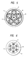
- the tape slot type optical cable of Japan is an optical cable which has the largest number of optical fibers.
- the number of optical fibers reaches 1000 at largest, and the packing density of coated optical fibers per unit area is about 0.8 coated optical fibers per mm 2 .
- the tape slot type optical cable is superior in workability for taking out the tape type optical unit.
- the waterproof property can be simply provided by using water-absorbing press-winding tape, as stated in "Characteristic of Simple-Waterproof Optical Fiber" (1988 Autumn Meeting of the Institute of Electronics, Information and Communication Engineers of Japan, B-376).
- a tape tube type optical cable that is, a high- fiber-count optical cable of AT & T Corporation in the United States (International Wire & Cable Symposium Proceedings 1982, p.396) has an optical-fiber packing density of about 1.3 coated optical fibers per mm 2 .
- the tape tube type optical cable is one of the multifiber optical cables which are the most superior in high-density property.
- the tape tube type optical cable has a problem in workability in taking out the tape type optical units. Further, there is another problem in that it is necessary to seal a gel-like waterproofing admixture into the tube in order to make the waterproof property sufficient and therefore the workability in connection of the optical cable is lowered.
- the tape type optical units are pressed against the respective groove bottoms and subjected to side pres sure by the force which acts toward the center of the slotted rod.
- the volume of the central portion of the slotted rod is useless to thereby lower the efficiency of accommodation.
- a multi- layer structure as shown in Fig. 7 may be considered. In such a structure, however, the workability in taking out the tape-type optical units in a central layer is extremely lowered.
- Document EP-A-0 280 279 discloses a tape and slot type optical cable having a core with a plurality of spiral-shaped grooves. Thereby, the groove dimensions are defined in relationship to the dimension of the optical fiber tape for an improvement of the transmission and mechanical strength characteristics of the optical cable.
- the optical fiber cable described in JP-A-63-228 114 consists of a cable body with a straight groove which accommodates an optical fiber unit. Furthermore, the body includes tension members which are adapted for shifting the neutral plane of bending in an off-centered position. The dimensions of the groove are selected so as to position the optical fiber unit into the neutral plane of bending.
- An aerial optical fiber cable with a straight slotted core member accommodating an optical fiber unit is described in document EP-A-0 216 548.
- the slot of the core member can be provided with a substantially rectangular cross-section being adapted to the shape of the accommodated optical fiber tape.
- the object of the present invention is to provide an improved optical cable comprising at least one multi-fiber optical unit wherein the optical cable represents a design concept which allows a reduction of side pressures applied to the optical unit and an improved saving in space.
- optical cable with the features of claim 1.
- Advantageous embodiments of the optical cable are defined in the dependent claims.
- the optical cable uses multifiber optical units, each of the multifiber optical units having a lamination body of a tape-type optical unit accommodated in a groove formed in a rod-like member, the tape-type optical unit being constituted by a plurality of optical fibers arranged in one row and coated collectively, wherein the distance between the center of the rod-like member and a bottom portion of the groove is made to be equal to or larger than a half of the height of the lamination body.
- the multifiber optical units may be twisted in one direction or twisted in a condition so as to be reversed alternately in opposite directions.
- strength members may be provided on an outside portion of each of the multifiber optical units.
- the groove is formed in the circular rod-like member so as to reach the central portion as shown in Fig. 3, the efficiency of accommodating optical fibers in the multifiber high-density optical cable having coated optical fibers not less than 500 or not less than 1000 is improved, and the diameter of the cable can be made smaller than that of the tape slot type optical cable.
- the tape type optical unit is arranged substantially at the center of the multifiber optical unit so that the tape type optical unit is hardly pressed against the groove bottom in the normal state.
- the tape type optical unit may be sometimes pressed against the groove bottom in a momentary condition, fine bending of the optical fibers due to side pressure can be much reduced even in such a case.
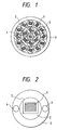
- Fig. 1 is a section of the optical cable which is an embodiment of the present invention.
- Fig. 2 is a section of the optical cable which is another embodiment of the present invention.
- Fig. 3 is a section of an embodiment of the multifiber optical unit to be used in the optical cable according to the present invention.
- Fig. 4 is a section of another embodiment of the multifiber optical unit to be used in the optical cable according to the present invention.
- Fig. 5 is a section of an example of a conventional tape slot type optical cable.
- Fig. 6 is a section of another example of a conventional tape slot type optical cable.
- Fig. 7 is a section of an example of a multi-layer structure tape slot type optical cable.
- Fig. 8 is a section of an example of a conventional tape tube type optical cable.
- multifiber optical units 1 were layer-twisted in one direction around a central tension body 4, further multi fiber optical units 1 were layer-twisted in one direction on the outside of the first-mentioned twisted multifiber units 1, and then a sheath was applied thereto.
- a multifiber optical unit was arranged in the center of the optical cable, a sheath 2 was applied to the outside of the multifiber optical unit, and two strength members 4 were arranged in the sheath 2 so as to be in opposition to each other.
- a circular rod-like member 2 is made of high-density polyethylene and has a twisted rectangular groove.
- the material to be used for the circular rod-like member 2 may be plastic such as polypropylene or the like which is superior in extrusion molding property or may be metal such as aluminum which is superior in working property.
- each coated optical fiber to be used has a fine outer diameter of 200 ⁇ m.
- 16 coated optical fibers are aligned so as to be a tape-like arrangement and 14 tape-like arrangements are laminated one on one into a lamination body, and the lamination body is inserted into the rectangular groove of the circular rod-like member. After accommodated into the groove, the tape type optical unit 1 is held in the groove by means of press-winding tape 7.
- the relation between the depth of the groove and the height of the lamination body is selected so that the center of the laminated tape type optical unit substantially agrees with the center of the circular rod-like member so that the tape type optical unit is not subjected to side pressure. Further, the distance between the center of the rod-like member and a bottom portion of said groove is made to be equal to or larger than a half of the height of the lamination body. Further more, the groove is formed in the circular rod-like member so as to reach the central portion as shown in Fig. 3.
- the press-winding tape 7 may be plastic tape. Particularly in the case where there is no problem in waterproof property, plastic may be directly extruded pipe-like so as to cover the tape type optical unit. In the case where the water proof becomes a problem, each coated optical fiber per se may be made superior in waterproof property, or a material having water- absorbing property may be used for the press-winding tape.
- the shape of the optical fiber accommodating portion formed in the circular rod-like member substantially rectangular brings an effect of suppressing the disorder of the arrangement of the tape type optical units and a further effect of improving the waterproof property because no excessive space is purposely provided. Further, in the case where the waterproof property becomes a problem, water-absorbing press-winding tape may be used at the opening portion to thereby be useful in preventing the connection workability from lowering.
- the residual strain of the optical fibers after formed into a cable was selected to be not higher than 0.02 % taking the long-time reliability of the optical fibers into consideration, and in each step in a cable manufacturing process, the tension of each of the members such as the circular rod-like member, the tape type optical unit, the multifiber optical unit, the tension force body, etc. was selectively adjusted.
- the embodiment of the optical cable shown Fig. 1 becomes a super-multifiber high-density optical cable having an outer diameter of 47.2 mm, 4032 coated optical fibers, and optical-fiber packing density of about 2.3 coated optical fibers per mm 2 .
- the optical cable according to the present invention is superior in the multifiber high-density property, in optical-fiber taking-out property and in connection workability.
- the influence of side pressure onto the optical fibers could be reduced.
- optical cable is effectively used particularly for a multifiber optical cable such as a subscriber optical cable or the like.
Landscapes
- Physics & Mathematics (AREA)
- General Physics & Mathematics (AREA)
- Optics & Photonics (AREA)
- Communication Cables (AREA)
- Light Guides In General And Applications Therefor (AREA)
- Optical Fibers, Optical Fiber Cores, And Optical Fiber Bundles (AREA)
Applications Claiming Priority (2)
| Application Number | Priority Date | Filing Date | Title |
|---|---|---|---|
| JP130212/91 | 1991-06-03 | ||
| JP3130212A JP2680943B2 (ja) | 1991-06-03 | 1991-06-03 | 光ケーブル |
Publications (2)
| Publication Number | Publication Date |
|---|---|
| EP0517144A1 EP0517144A1 (en) | 1992-12-09 |
| EP0517144B1 true EP0517144B1 (en) | 1997-09-17 |
Family
ID=15028773
Family Applications (1)
| Application Number | Title | Priority Date | Filing Date |
|---|---|---|---|
| EP92109220A Expired - Lifetime EP0517144B1 (en) | 1991-06-03 | 1992-06-01 | Optical cable |
Country Status (9)
| Country | Link |
|---|---|
| US (1) | US5233678A (Sortimente) |
| EP (1) | EP0517144B1 (Sortimente) |
| JP (1) | JP2680943B2 (Sortimente) |
| KR (1) | KR960014130B1 (Sortimente) |
| CN (1) | CN1030109C (Sortimente) |
| AU (1) | AU652108B2 (Sortimente) |
| CA (1) | CA2070229C (Sortimente) |
| DE (1) | DE69222223T2 (Sortimente) |
| TW (1) | TW225051B (Sortimente) |
Families Citing this family (27)
| Publication number | Priority date | Publication date | Assignee | Title |
|---|---|---|---|---|
| JP2680943B2 (ja) * | 1991-06-03 | 1997-11-19 | 住友電気工業株式会社 | 光ケーブル |
| US5229851A (en) * | 1992-04-02 | 1993-07-20 | Pirelli Cable Corporation | Optical fiber cable with large number of ribbon units containing optical fibers and enclosed in tubes |
| JPH07333475A (ja) * | 1994-06-03 | 1995-12-22 | Fujikura Ltd | 多芯リボンを収納した光ファイバケーブル |
| US6052502A (en) * | 1997-09-22 | 2000-04-18 | Siecor Corporation | Ribbon optical cable having improved strength |
| US6178278B1 (en) | 1997-11-13 | 2001-01-23 | Alcatel | Indoor/outdoor dry optical fiber cable |
| US6169834B1 (en) | 1998-05-13 | 2001-01-02 | Alcatel | Slotted composite cable having a cable housing with a tubular opening for copper pairs and a slot for an optical fiber |
| DE19838351C2 (de) * | 1998-08-14 | 2000-10-26 | Siemens Ag | Optisches Kabel und Kabelanordnung |
| US6253012B1 (en) | 1998-11-12 | 2001-06-26 | Alcatel | Cycled fiber lock for cross-functional totally dry optical fiber loose tube cable |
| JP2000241685A (ja) * | 1999-02-19 | 2000-09-08 | Sumitomo Electric Ind Ltd | 光ケーブル |
| US6480654B1 (en) * | 1999-07-14 | 2002-11-12 | Alcoa Fujikura Ltd. | High fiber count ribbon sub-unit breakout cable |
| US20030174977A1 (en) * | 2001-02-05 | 2003-09-18 | Yaron Mayer | System and method for transferring much more information in optic fiber cables by significantly increasing the number of fibers per cable |
| US20070047885A1 (en) * | 2000-11-21 | 2007-03-01 | Yaron Mayer | System and method for transferring much more information in optic fiber cables by significantly increasing the number of fibers per cable |
| US20060140557A1 (en) * | 2001-03-30 | 2006-06-29 | Parris Donald R | Fiber optic cable with strength member formed from a sheet |
| US7079734B2 (en) * | 2004-12-22 | 2006-07-18 | Corning Cable Systems Llc | Fiber optic drop cables suitable for fiber to the subscriber applications |
| BR112014021671B1 (pt) * | 2012-03-02 | 2020-09-24 | Ofs Fitel, Llc | Cabos aéreos de fibra ótica |
| US8620124B1 (en) | 2012-09-26 | 2013-12-31 | Corning Cable Systems Llc | Binder film for a fiber optic cable |
| US11287589B2 (en) | 2012-09-26 | 2022-03-29 | Corning Optical Communications LLC | Binder film for a fiber optic cable |
| US9091830B2 (en) | 2012-09-26 | 2015-07-28 | Corning Cable Systems Llc | Binder film for a fiber optic cable |
| US9482839B2 (en) | 2013-08-09 | 2016-11-01 | Corning Cable Systems Llc | Optical fiber cable with anti-split feature |
| US9075212B2 (en) | 2013-09-24 | 2015-07-07 | Corning Optical Communications LLC | Stretchable fiber optic cable |
| US8805144B1 (en) | 2013-09-24 | 2014-08-12 | Corning Optical Communications LLC | Stretchable fiber optic cable |
| US8913862B1 (en) | 2013-09-27 | 2014-12-16 | Corning Optical Communications LLC | Optical communication cable |
| US9594226B2 (en) | 2013-10-18 | 2017-03-14 | Corning Optical Communications LLC | Optical fiber cable with reinforcement |
| WO2017122518A1 (ja) * | 2016-01-13 | 2017-07-20 | 住友電気工業株式会社 | 間欠連結型光ファイバテープ心線、光ケーブルおよび間欠連結型光ファイバテープ心線の製造方法 |
| JP6840659B2 (ja) * | 2017-12-19 | 2021-03-10 | 株式会社フジクラ | 光ファイバケーブル |
| CN111474651A (zh) * | 2020-05-15 | 2020-07-31 | 江苏亨通海洋光网系统有限公司 | 一种500芯及以上芯数层绞式无中继海底光缆 |
| US20230305251A1 (en) * | 2020-09-28 | 2023-09-28 | Sumitomo Electric Industries, Ltd. | Optical fiber cable and cable with connector |
Citations (1)
| Publication number | Priority date | Publication date | Assignee | Title |
|---|---|---|---|---|
| FR2534385A1 (fr) * | 1982-10-08 | 1984-04-13 | Cabeltel | Cable optique a structure libre, notamment monovoie |
Family Cites Families (13)
| Publication number | Priority date | Publication date | Assignee | Title |
|---|---|---|---|---|
| GB8406636D0 (en) * | 1984-03-14 | 1984-04-18 | Bicc Plc | Flexible elongate body |
| JPS6153612A (ja) * | 1984-08-24 | 1986-03-17 | Nippon Telegr & Teleph Corp <Ntt> | スペ−サ形光ケ−ブルの製造方法 |
| DE3650256T2 (de) * | 1985-09-14 | 1995-06-29 | Stc Plc | Optisches Kabel. |
| JPH01163710A (ja) * | 1987-02-25 | 1989-06-28 | Sumitomo Electric Ind Ltd | 光ケ−ブル |
| JPH07111493B2 (ja) * | 1987-03-17 | 1995-11-29 | 日本電信電話株式会社 | 光フアイバケ−ブル |
| DE3811126A1 (de) * | 1988-03-31 | 1989-10-12 | Siemens Ag | Optisches kabel mit mehreren buendelelementen |
| US4900126A (en) * | 1988-06-30 | 1990-02-13 | American Telephone & Telegraph Co. | Bonded array of transmission media |
| GB8908446D0 (en) * | 1989-04-14 | 1989-06-01 | Bicc Plc | Optical cable |
| GB2233779B (en) * | 1989-07-01 | 1993-05-05 | Stc Plc | Optical fibre cable |
| GB2237655B (en) * | 1989-10-12 | 1993-04-28 | Stc Plc | Aerial optical fibre cable |
| US5179611A (en) * | 1990-07-17 | 1993-01-12 | Tokai Rubber Industries, Ltd. | Optical fiber cable having a water absorptive member |
| US5067830A (en) * | 1990-12-21 | 1991-11-26 | Siecor Corporation | Indented tube for optical ribbon |
| JP2680943B2 (ja) * | 1991-06-03 | 1997-11-19 | 住友電気工業株式会社 | 光ケーブル |
-
1991
- 1991-06-03 JP JP3130212A patent/JP2680943B2/ja not_active Expired - Lifetime
-
1992
- 1992-06-01 EP EP92109220A patent/EP0517144B1/en not_active Expired - Lifetime
- 1992-06-01 DE DE69222223T patent/DE69222223T2/de not_active Expired - Fee Related
- 1992-06-02 CA CA002070229A patent/CA2070229C/en not_active Expired - Fee Related
- 1992-06-02 KR KR1019920009535A patent/KR960014130B1/ko not_active Expired - Fee Related
- 1992-06-02 AU AU17376/92A patent/AU652108B2/en not_active Ceased
- 1992-06-03 US US07/892,944 patent/US5233678A/en not_active Expired - Fee Related
- 1992-06-03 CN CN92104449A patent/CN1030109C/zh not_active Expired - Fee Related
- 1992-06-08 TW TW081104449A patent/TW225051B/zh active
Patent Citations (1)
| Publication number | Priority date | Publication date | Assignee | Title |
|---|---|---|---|---|
| FR2534385A1 (fr) * | 1982-10-08 | 1984-04-13 | Cabeltel | Cable optique a structure libre, notamment monovoie |
Also Published As
| Publication number | Publication date |
|---|---|
| AU652108B2 (en) | 1994-08-11 |
| DE69222223T2 (de) | 1998-01-15 |
| CA2070229A1 (en) | 1992-12-04 |
| CA2070229C (en) | 1997-03-25 |
| JPH04355418A (ja) | 1992-12-09 |
| CN1067746A (zh) | 1993-01-06 |
| AU1737692A (en) | 1992-12-10 |
| KR960014130B1 (ko) | 1996-10-14 |
| JP2680943B2 (ja) | 1997-11-19 |
| CN1030109C (zh) | 1995-10-18 |
| DE69222223D1 (de) | 1997-10-23 |
| KR930000976A (ko) | 1993-01-16 |
| US5233678A (en) | 1993-08-03 |
| TW225051B (Sortimente) | 1994-06-11 |
| EP0517144A1 (en) | 1992-12-09 |
Similar Documents
| Publication | Publication Date | Title |
|---|---|---|
| EP0517144B1 (en) | Optical cable | |
| US5229851A (en) | Optical fiber cable with large number of ribbon units containing optical fibers and enclosed in tubes | |
| US4729628A (en) | Fiber optic dropwire | |
| US6229944B1 (en) | Optical fiber cable | |
| US4906067A (en) | Optical cable comprising a plurality of bundle elements | |
| EP0361863B1 (en) | Communication cable having water blocking provisions in core | |
| EP0784220B1 (en) | Fiber optic micro cable | |
| CA1194714A (en) | Composite overhead transmission line | |
| US4828352A (en) | S-Z stranded optical cable | |
| US4422718A (en) | Submarine optical fiber cable | |
| US6014487A (en) | Fiber optic cable | |
| CA2143774C (en) | Optical fiber cable containing ribbon fibers | |
| EP0694797A1 (en) | Submarine cable having a centrally located tube containing optical fibers | |
| EP3025174B1 (en) | Fiber optic ribbon | |
| KR940000839B1 (ko) | 광파이버 유닛 | |
| US5371825A (en) | Fiber optic cable with surround kingwire and method of making same | |
| CN113724935A (zh) | 一种复合带状光缆 | |
| US4830457A (en) | Optical cable connecting section in electric power and optical composite cable | |
| US6798958B2 (en) | Cable with a high density of optical fibers | |
| JP3058203B2 (ja) | 光ケーブル | |
| US4521072A (en) | Optical cable designed to withstand high pressures | |
| GB2227855A (en) | Optical fibre cable | |
| JP2001194567A (ja) | 光ファイバケーブル | |
| JPH06201956A (ja) | 光ファイバケーブル | |
| CA2173886A1 (en) | Method for fabricating a submarine cable having a bi-metal tube core containing optical fibers |
Legal Events
| Date | Code | Title | Description |
|---|---|---|---|
| PUAI | Public reference made under article 153(3) epc to a published international application that has entered the european phase |
Free format text: ORIGINAL CODE: 0009012 |
|
| AK | Designated contracting states |
Kind code of ref document: A1 Designated state(s): DE FR GB IT |
|
| 17P | Request for examination filed |
Effective date: 19930219 |
|
| 17Q | First examination report despatched |
Effective date: 19941012 |
|
| GRAG | Despatch of communication of intention to grant |
Free format text: ORIGINAL CODE: EPIDOS AGRA |
|
| GRAH | Despatch of communication of intention to grant a patent |
Free format text: ORIGINAL CODE: EPIDOS IGRA |
|
| GRAH | Despatch of communication of intention to grant a patent |
Free format text: ORIGINAL CODE: EPIDOS IGRA |
|
| GRAA | (expected) grant |
Free format text: ORIGINAL CODE: 0009210 |
|
| AK | Designated contracting states |
Kind code of ref document: B1 Designated state(s): DE FR GB IT |
|
| REF | Corresponds to: |
Ref document number: 69222223 Country of ref document: DE Date of ref document: 19971023 |
|
| ITF | It: translation for a ep patent filed | ||
| ET | Fr: translation filed | ||
| PLBE | No opposition filed within time limit |
Free format text: ORIGINAL CODE: 0009261 |
|
| STAA | Information on the status of an ep patent application or granted ep patent |
Free format text: STATUS: NO OPPOSITION FILED WITHIN TIME LIMIT |
|
| 26N | No opposition filed | ||
| REG | Reference to a national code |
Ref country code: GB Ref legal event code: IF02 |
|
| PGFP | Annual fee paid to national office [announced via postgrant information from national office to epo] |
Ref country code: GB Payment date: 20040526 Year of fee payment: 13 |
|
| PGFP | Annual fee paid to national office [announced via postgrant information from national office to epo] |
Ref country code: FR Payment date: 20040608 Year of fee payment: 13 |
|
| PGFP | Annual fee paid to national office [announced via postgrant information from national office to epo] |
Ref country code: DE Payment date: 20040610 Year of fee payment: 13 |
|
| PG25 | Lapsed in a contracting state [announced via postgrant information from national office to epo] |
Ref country code: IT Free format text: LAPSE BECAUSE OF NON-PAYMENT OF DUE FEES;WARNING: LAPSES OF ITALIAN PATENTS WITH EFFECTIVE DATE BEFORE 2007 MAY HAVE OCCURRED AT ANY TIME BEFORE 2007. THE CORRECT EFFECTIVE DATE MAY BE DIFFERENT FROM THE ONE RECORDED. Effective date: 20050601 Ref country code: GB Free format text: LAPSE BECAUSE OF NON-PAYMENT OF DUE FEES Effective date: 20050601 |
|
| PG25 | Lapsed in a contracting state [announced via postgrant information from national office to epo] |
Ref country code: DE Free format text: LAPSE BECAUSE OF NON-PAYMENT OF DUE FEES Effective date: 20060103 |
|
| PG25 | Lapsed in a contracting state [announced via postgrant information from national office to epo] |
Ref country code: FR Free format text: LAPSE BECAUSE OF NON-PAYMENT OF DUE FEES Effective date: 20060228 |
|
| GBPC | Gb: european patent ceased through non-payment of renewal fee |
Effective date: 20050601 |
|
| REG | Reference to a national code |
Ref country code: FR Ref legal event code: ST Effective date: 20060228 |