EP0516858B1 - Dispositif d'allumage - Google Patents
Dispositif d'allumage Download PDFInfo
- Publication number
- EP0516858B1 EP0516858B1 EP91920769A EP91920769A EP0516858B1 EP 0516858 B1 EP0516858 B1 EP 0516858B1 EP 91920769 A EP91920769 A EP 91920769A EP 91920769 A EP91920769 A EP 91920769A EP 0516858 B1 EP0516858 B1 EP 0516858B1
- Authority
- EP
- European Patent Office
- Prior art keywords
- gas
- nozzle
- pipe
- gas pipe
- injection nozzle
- Prior art date
- Legal status (The legal status is an assumption and is not a legal conclusion. Google has not performed a legal analysis and makes no representation as to the accuracy of the status listed.)
- Expired - Lifetime
Links
- 239000007789 gas Substances 0.000 claims description 107
- 239000002737 fuel gas Substances 0.000 claims description 26
- 238000002347 injection Methods 0.000 claims description 24
- 239000007924 injection Substances 0.000 claims description 24
- 239000000446 fuel Substances 0.000 claims description 7
- WABPQHHGFIMREM-UHFFFAOYSA-N lead(0) Chemical compound [Pb] WABPQHHGFIMREM-UHFFFAOYSA-N 0.000 abstract 4
- 230000003247 decreasing effect Effects 0.000 abstract 1
- 239000000463 material Substances 0.000 description 3
- 238000012856 packing Methods 0.000 description 2
- 230000000881 depressing effect Effects 0.000 description 1
- 239000003989 dielectric material Substances 0.000 description 1
- 239000002184 metal Substances 0.000 description 1
- 230000002093 peripheral effect Effects 0.000 description 1
- 239000004033 plastic Substances 0.000 description 1
- 229920003023 plastic Polymers 0.000 description 1
- 239000011347 resin Substances 0.000 description 1
- 229920005989 resin Polymers 0.000 description 1
Images


Classifications
-
- F—MECHANICAL ENGINEERING; LIGHTING; HEATING; WEAPONS; BLASTING
- F23—COMBUSTION APPARATUS; COMBUSTION PROCESSES
- F23Q—IGNITION; EXTINGUISHING-DEVICES
- F23Q2/00—Lighters containing fuel, e.g. for cigarettes
- F23Q2/28—Lighters characterised by electrical ignition of the fuel
- F23Q2/285—Lighters characterised by electrical ignition of the fuel with spark ignition
- F23Q2/287—Lighters characterised by electrical ignition of the fuel with spark ignition piezoelectric
Definitions
- This invention relates to an igniting device according to the pre-characterizing part of claim 1.
- Such igniting device injects a flame from a nozzle by igniting fuel gas discharged from a built-in gas reservoir.
- an igniting device of this type e. g. an igniting rod or table gas lighter
- a flame is injected from a tip of a rod-like portion which projects from a valve mechanism which controls gas supply from a gas reservoir.
- a gas pipe for supplying fuel gas to a fuel nozzle on the tip of the rod-like portion and a wire for supplying a discharge voltage for producing spark extend from the body portion and respectively connected to the fuel nozzle and a discharge electrode on the tip of the rod-like portion.
- said wire is an uncovered wire extending coaxially within an insulating gas pipe, or is embedded within the insulating wall of the gas pipe.
- misfire is apt to occur due to delay in discharge of fuel gas.
- the piezoelectric unit is arranged to be actuated a certain time after opening of the valve mechanism in response to depression of an ignition lever.
- the spark is sometimes produced before the fuel gas reaches the nozzle and sometimes produced after a large amount of fuel gas is discharged from the nozzle, and conventionally, it has been difficult to steadily ignite the fuel gas.
- the time required for the fuel gas to reach the nozzle can be shortened by increasing the flow speed of the gas through the gas pipe by reducing the inner diameter of the gas pipe.
- the gas pipe having a small inner diameter is difficult to connect and is not preferable from the viewpoint of production.
- the primary object of the present invention is to provide an igniting device of the type defined in the pre-characterizing part of claim 1, in which the gas passage to the nozzle can be small in the effective cross-sectional area with a high reliability and a simple structure and the fuel gas can be steadily ignited.
- a covered wire which electrically connects a piezoelectric unit and a fuel nozzle is passed through a gas pipe for supplying fuel gas to the fuel nozzle, thereby reducing the effective cross-sectional area of the gas passage inside the gas pipe.
- the covered wire is passed through the gas pipe to extend along the longitudinal axis of the gas pipe.
- the effective cross-sectional area of the gas passage can be easily reduced and the flowing speed of the fuel flowing through the gas passage can be increased without reducing the inner diameter of the gas pipe itself. Since the inner diameter of the gas pipe need not be reduced, the gas pipe can be easily produced with a high reliability and the gas pipe can be easily connected to the parts associated therewith.
- the covered wire When the covered wire extends along the longitudinal axis of the gas pipe, the distance between the covered wire and the ground is enlarged and the stray capacitance is minimized, whereby leak of the discharge voltage can be minimized.
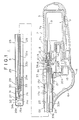
- Figure 1 is a cross-sectional view of an igniting rod in accordance with an embodiment of the present invention
- Figure 2 is a horizontal cross-sectional view of the same
- Figure 3 is an enlarged view of a part of Figure 1.
- the igniting device 1 comprises a body portion 2 and a rod portion 3 extending from the body portion 2.
- the body portion 2 and the rod portion 3 are in the form of separate units which are integrated into the igniting device 1.
- the body portion 2 has a casing comprising a reservoir cover 5 and an intermediate casing 6 disposed in front of the reservoir cover 5.
- the reservoir cover 5 is in the form a tubular member open at the front end, and the intermediate casing 6 comprising left and right halves.
- the intermediate casing 6 has an opening 6a for accommodating an ignition lever in the lower portion thereof and an opening 6b in the front end thereof through which the rod portion 3 is received in the body portion 2 and connected thereto.
- a gas reservoir 7 in which pressurized fuel gas is stored is accommodated in the reservoir cover 5.
- the gas reservoir 7 comprises a reservoir body 7a and an upper lid 7b connected to the reservoir body 7a.
- a valve mechanism 8 for controlling gas supply from the gas reservoir 7 is provided in the upper lid 7b. That is, a wick 9 is inserted into the gas reservoir 7 and the fuel gas is supplied through the wick 9 and a nozzle member 10 is disposed in the gas supply passage.
- the nozzle member 10 is urged rearward by a spring, and when the nozzle member 10 is moved forward, the gas supply passage is opened and the fuel gas is supplied, and when the nozzle member 10 is returned rearward under the force of the spring, the gas supply passage is closed and gas supply is interrupted.
- the amount of gas supply or the size of the flame is adjusted by rotating a flame adjustment knob 13 which is connected to an adjustment sleeve 12 and projects outward.
- a sealed packing 15 is mounted on the tip of the nozzle member 10 forward of the lever 14.
- the other end portion of the lever 14 is connected to a piezoelectric unit 20 which will be described later.
- Said ignition lever 18 is mounted inside the opening 6a of the intermediate casing 6 to be slidable back and forth.
- the piezoelectric unit 20 is provided between the the ignition lever 18 and the upper lid 7b of the gas reservoir 7.
- the piezoelectric unit 20 is for supplying discharge voltage, and when the ignition lever 18 is pulled rearward, a sliding portion 20a is moved rearward to cause a projection 20b to engage with the lever 14 and rotate it and discharge voltage generated in the piezoelectric unit 20 is supplied.
- the lever 14 is L-shaped and is supported to rotate about a pivot 14a.
- said one end of the lever 14 pulls forward the nozzle member 10 to open the gas supply passage.
- the projection 20b doubles as one terminal for the discharge voltage and is electrically connected to the nozzle member 10 through the lever 14 which is made of conductive resin.
- the sliding member 20a of the piezoelectric unit 20 doubles as the other terminal for the discharge voltage and is electrically connected to a contact 21a by way of an earth plate 21.
- the contact 21a is disposed beside an intermediate portion of a pipe holder 17 which will be described later. That is, the earth plate 21 is sandwiched between the piezoelectric unit 20 and the ignition lever 18 at its base portion, is bent forward above the ignition lever 18, and then is cranked at portion near a flange portion 17d of the pipe holder 17.
- the front end of the earth plate 21 is formed into the contact 21a which is disposed on one side of the central axis of the pipe holder 17 and is pressed against the pipe holder 17 toward the central axis thereof. The earth plate 21 is moved in response to slide of the ignition lever 18.
- the rod portion 3 comprises a metal tubular member 25 and a gas injection nozzle 26 which is mounted in the front end of the tubular member 25.
- the gas injection nozzle 26 has a nozzle tip 27 on its front end and is fitted on the front end of a gas pipe 28 at its rear end.
- a nozzle cover 30 is mounted on the gas injection nozzle 26 to surround it.
- the nozzle cover 30 is made of dielectric material such as plastics and has holder portion 29 which is fitted on the gas injection nozzle 26 and the front end portion of the gas pipe 28.
- the holder portion 29 has a flared rear end portion 29a which is square in cross-section and positioned coaxially with the tubular member 25 in contact with the inner surface of the tubular member 25.
- the nozzle cover 30 is further provided with a cover portion 31 which is connected to an upper portion of the holder portion 29 and extends forward therefrom.
- the front end portion of the gas injection nozzle 26 projects forward from the holder portion 29 and the cover portion 31 surrounds the front end portion of the gas injection nozzle 26 at a predetermined distance therefrom except a lower portion of the gas injection nozzle 26.
- the cover portion 31 has a front wall portion 31a which extends inward in a position forwardly distant from the tip of the nozzle tip 27.
- the front wall portion 31a is cut away to form a V-shaped opening 31b which is flared upward from a portion substantially aligned with the nozzle tip 27. As shown in Figures 2 and 3, the opening 31b extends inward of the cover portion 31 on the side of a discharge electrode to such an extent that the nozzle tip 27is exposed so that fuel gas is surely ignited.
- the opening 31b is extended downward in a slit-like form, thereby dividing the front wall portion 31a in two sectors opposed to each other as viewed from the front.
- a pair of engagement grooves 31c are formed on opposite sides of the cover portion 31 and are engaged with engagement pieces 25d of the tubular member 25 which are bent inward.
- the tubular member 25 has a front end wall and a flame port 25a through which flame is injected outward is formed in the central portion of the front end wall.
- a plurality of air intake ports 25b are formed in the tubular member 25 behind the flame port 25a. Further, a part of the tubular member 25 is bent inward behind the air intake ports 25b to form a discharge electrode 32. The portion of the tubular member 25 at which the discharge electrode 32 is formed forms another air intake port 25b.
- Further four elongated air intake ports 25c are formed in the tubular member 25 to extend in the longitudinal direction of the tubular member 25 at portions opposed to the holder portion 29 of the nozzle cover 30.
- the nozzle cover 30 is accommodated in the tubular member 25 so that the discharge electrode 32 is positioned above the V-shaped opening 31a thereof. Air introduced into the inside of the tubular member 25 through the air intake ports 25c formed around the holder portion 29 of the nozzle cover 30 flows into the space in the cover portion 31.
- the gas pipe 28 the front end portion of which is inserted into the holder portion 29 of the nozzle cover 30 is for leading the fuel gas to the gas injection nozzle 26 and is made of hard material.
- the gas pipe 28 extends through the tubular member 25 along the central axis thereof and the rear end portion of the gas pipe 28 projects rearward outside the tubular member 25.
- the front end portion of said pipe holder 17 is fitted in the rear end portion of the tubular member 25 while the rear end portion of the gas pipe 28 is fitted in the front end portion of the pipe holder 17.
- a covered wire 33 having a cover 33a extends through the gas pipe 28 coaxially with the gas pipe 28.
- the covered wire 33 has an outer diameter slightly smaller than the inner diameter of the gas pipe 28, whereby a gas passage having a small effective cross-sectional area is formed between the outer surface of the covered wire 33 and the inner surface of the gas pipe 28.
- a groove 33b is formed in the cover 33a of the covered wire 33 to extend in the longitudinal direction thereof as clearly shown in Figure 4.
- the cover 33a is removed at front and rear end portions of the covered wire 33 and the core of the covered wire 33 is exposed at the front and rear end portions.
- a tubular terminal member 34 is mounted on the rear end portion of the gas pipe 28. That is, the front end portion of the terminal member 34 is fitted in the rear end portion of gas pipe 28 through the rear end of the pipe holder 17, and the rear end portion of the terminal member 34 is flared and fitted in the rear end portion of the pipe holder 17.
- the rear end portion of the exposed core of the covered wire 33 is connected to the terminal member 34 and the front end portion of the same is connected to the gas injection nozzle 26, whereby the terminal member 34 and the gas injection nozzle 26 are electrically connected by the covered wire 33.
- the pipe holder 17 is a tubular member having a longitudinal through hole 17a into which the rear end portion of the gas pipe 28 is inserted.
- the through hole 17a has a large diameter at the front end portion and is smoothly tapered rearward to form a guide surface.
- the pipe holder 17 is further provided with an annular groove 17b which is formed on the outer peripheral surface of the rear end portion thereof and is adapted to be engaged with an engagement portion 6c formed on the inner surface of the intermediate casing 6.
- the sealed packing 15 mounted on the tip of the nozzle member 10 of the valve mechanism 8 is adapted to abut against the flared rear end portion of the terminal member 34.
- the front end portion of the pipe holder 17 is fitted in the rear end portion of the tubular member 25 and the rear end face of the tubular member 25 is in abutment against a flange portion 17d formed on the outer surface of the pipe holder 17.
- the rod portion 3 is connected to the body portion 2 in the following manner. That is, the pipe holder 17 in which the gas pipe 28 and the tubular member 25 have been incorporated is set to one of the halves of the intermediate casing 6 of the body portion 2 so that the annular groove 17b of the pipe holder 17 is engaged with the engagement portion 6c of the intermediate casing 6, and then the other half of the intermediate casing 6 is incorporated with said one of the halves.
- the terminal member 34 and the nozzle member 10 are connected, and the gas passage in the gas pipe 28 and the gas passage in the valve mechanism 8 communicate with each other. Further, the contact 21a of the earth plate 21 is in contact with the outer surface of the tubular member 25 and the discharge electrode 32 is electrically connected with the piezoelectric unit 20.
- the gas injection nozzle 26 is electrically connected with the piezoelectric unit 20 by way of the nozzle member 10, the terminal member 34 and the covered wire 33. Since the discharge voltage produced by the piezoelectric unit 20 is high alternating voltage, the discharge voltage can be applied to the nozzle tip 27 even if there is a slight gap between the nozzle member 10 and the terminal member 34 or between the terminal member 34 and the exposed rear end portion of the covered wire 33.
- the igniting rod 1 of this embodiment will be described, hereinbelow.
- the nozzle member 10 of the valve mechanism 8 is moved forward and the fuel gas is discharged from the gas reservoir 7 as described above.
- the fuel gas discharged from the gas reservoir 7 is injected from the nozzle tip 27 of the gas injection nozzle 26 through the space in the gas pipe 28 which is narrowed by the covered wire 33 inserted therein.
- the groove 33b formed on the outer surface of the covered wire 33 ensures the gas passage to the gas injection nozzle 26 even when the covered wire 33 is moved in the gas pipe 28 and the front or rear end face of the cover 33a is brought into contact with the end of the gas injection nozzle 26 or the terminal member 34.
- the piezoelectric unit 20 in response to operation of the ignition lever 18, produces an alternating discharge voltage which is applied between the discharge electrode 32 and the nozzle tip 27 in the rod portion 3, whereby the fuel gas injected from the nozzle tip 27 is ignited.
- the fuel gas can be stably supplied to the gas injection nozzle 26 in time by virtue of the narrowed gas passage in the gas pipe 28 and since a part of fuel injected from the nozzle tip 27 dwells in the cover portion 31 and is mixed with air introduced through the air intake ports 25c, the fuel gas injected from the nozzle tip 27 can be well ignited by spark produced by the discharge voltage. Further since the covered wire 33 is inserted into the gas pipe 28 at the center of the tubular member 25 which forms the ground, the distance between the ground and the wire 33 is maximized and stray capacitance in discharge of high alternating voltage is minimized, whereby leak is reduced and discharge energy is increased, thereby improving igniting performance of the igniting rod 1.
- the nozzle tip 27 is positioned in the cover portion 31 of the nozzle cover 30 and is covered with the nozzle cover 30 and the tubular member 25. Accordingly, wind, oil, fire work or the like which blows off flame cannot directly act on the nozzle tip 27, and the nozzle tip 27 and the gas injection nozzle 26 are protected from foreign matter which can adhere to the nozzle tip 27 and the gas injection nozzle 26 and weaken discharge spark.
- the body portion 2 and the rod portion 3 are separately formed and incorporated together later, they may be formed integrally.
- the gas pipe 28 may be formed of flexible material though preferably it is formed of hard material.
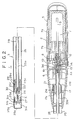
- FIG. 5 shows another embodiment of the present invention in the form of a table gas lighter.
- the table gas lighter of this embodiment is basically the same as the igniting rod of the aforesaid embodiment, and accordingly the analogous parts are given the same reference numerals.
- the casing portion 55 of the body portion 52 in which the valve mechanism 8 and the like are accommodated is shaped so that the lighter 50 can be erected.
- the gas reservoir 7 is shaped to conform to the shape of the casing portion 55.
- the ignition lever 54 for actuating the piezoelectric unit 20 provided in the body portion 52 is movable up and down, and the valve mechanism 8 is opened and the piezoelectric unit 20 is actuated to produce the discharge voltage in response to depression of the ignition lever 54. Further the igniting lever 54 forms an upper part of the casing portion 55.
- the rod portion 53 i.e., the tubular member 25 and the gas pipe 28 is shorter than that of the aforesaid embodiment, the gas injection nozzle 26, the nozzle cover 30, the covered wire 33 and the like are the substantially same as in the aforesaid embodiment in shape and function.
Landscapes
- Engineering & Computer Science (AREA)
- Chemical & Material Sciences (AREA)
- Combustion & Propulsion (AREA)
- Mechanical Engineering (AREA)
- General Engineering & Computer Science (AREA)
- Lighters Containing Fuel (AREA)
- Spark Plugs (AREA)
- Ignition Installations For Internal Combustion Engines (AREA)
Abstract
Claims (3)
- Dispositif d'allumage comprenant un réservoir de gaz (7) destiné à contenir un gaz combustible, un mécanisme à valve (10, 14) qui règle la transmission du gaz du réservoir (7), un tube de gaz (28) raccordé au mécanisme à valve (10, 14) à une première extrémité et à une buse (26) d'éjection de gaz à l'autre extrémité de manière que le gaz combustible provenant du réservoir (7) circule vers la buse (26) d'éjection de gaz par l'intermédiaire du tube de gaz (28), et une unité piézoélectrique (20) destinée à créer une tension de décharge entre la buse (26) d'éjection de gaz et une électrode de décharge (32) disposée près de la buse (26) d'éjection de gaz, un fil métallique (33) qui relie électriquement la buse (26) d'éjection de gaz à l'unité piézoélectrique (20) étant disposé dans le tube de gaz (28), caractérisé en ce que le fil métallique est un fil métallique recouvert (33) dont le diamètre externe est légèrement inférieur au diamètre interne du tube de gaz (28), afin que la section efficace du passage de gaz formé dans le tube de gaz (28) soit réduite.
- Dispositif d'allumage selon la revendication 1, dans lequel le fil recouvert (33) est placé coaxialement au tube de gaz (28), si bien que la capacité parasite est réduite au minimum.
- Dispositif d'allumage selon la revendication 1 ou 2, dans lequel une gorge (33b) est formée à la surface externe du fil recouvert (33), si bien qu'un passage de gaz est formé vers la buse (26) d'éjection de gaz.
Applications Claiming Priority (11)
| Application Number | Priority Date | Filing Date | Title |
|---|---|---|---|
| JP130578/90U | 1990-11-30 | ||
| JP13057990 | 1990-11-30 | ||
| JP13057890 | 1990-11-30 | ||
| JP130577/90U | 1990-11-30 | ||
| JP1990130577U JP2536865Y2 (ja) | 1990-11-30 | 1990-11-30 | 点火棒 |
| JP130579/90U | 1990-11-30 | ||
| JP96547/91U | 1991-11-25 | ||
| JP1991096547U JP2573994Y2 (ja) | 1990-11-30 | 1991-11-25 | 点火装置 |
| JP96548/91U | 1991-11-25 | ||
| JP1991096548U JP2573995Y2 (ja) | 1990-11-30 | 1991-11-25 | 点火装置 |
| PCT/JP1991/001665 WO1992009851A1 (fr) | 1990-11-30 | 1991-11-29 | Dispositif d'allumage |
Publications (3)
| Publication Number | Publication Date |
|---|---|
| EP0516858A1 EP0516858A1 (fr) | 1992-12-09 |
| EP0516858A4 EP0516858A4 (en) | 1994-05-11 |
| EP0516858B1 true EP0516858B1 (fr) | 1996-01-31 |
Family
ID=27525798
Family Applications (3)
| Application Number | Title | Priority Date | Filing Date |
|---|---|---|---|
| EP91920813A Expired - Lifetime EP0515693B1 (fr) | 1990-11-30 | 1991-11-29 | Dispositif d'allumage |
| EP91920814A Expired - Lifetime EP0515694B1 (fr) | 1990-11-30 | 1991-11-29 | Dispositif d'allumage |
| EP91920769A Expired - Lifetime EP0516858B1 (fr) | 1990-11-30 | 1991-11-29 | Dispositif d'allumage |
Family Applications Before (2)
| Application Number | Title | Priority Date | Filing Date |
|---|---|---|---|
| EP91920813A Expired - Lifetime EP0515693B1 (fr) | 1990-11-30 | 1991-11-29 | Dispositif d'allumage |
| EP91920814A Expired - Lifetime EP0515694B1 (fr) | 1990-11-30 | 1991-11-29 | Dispositif d'allumage |
Country Status (9)
| Country | Link |
|---|---|
| US (3) | US5326256A (fr) |
| EP (3) | EP0515693B1 (fr) |
| CN (3) | CN1043077C (fr) |
| CA (3) | CA2073977C (fr) |
| DE (3) | DE69114273T2 (fr) |
| ES (3) | ES2078555T3 (fr) |
| HK (3) | HK1007439A1 (fr) |
| MX (1) | MX174397B (fr) |
| WO (3) | WO1992009852A1 (fr) |
Families Citing this family (52)
| Publication number | Priority date | Publication date | Assignee | Title |
|---|---|---|---|---|
| US5509722A (en) * | 1994-04-15 | 1996-04-23 | Burns Aerospace Corporation | Convertible passenger seat assembly and grouping of passenger seat assemblies |
| US5697775A (en) * | 1994-08-18 | 1997-12-16 | Tokai Corporation | Safety device in lighting rods |
| US5897308A (en) * | 1994-08-18 | 1999-04-27 | Tokai Corporation | Safety device in lighting rods |
| USD377736S (en) * | 1995-12-07 | 1997-02-04 | Scripto-Tokai Corporation | Utility lighter |
| USD379415S (en) * | 1996-02-16 | 1997-05-27 | U.S. Catalytic Corporation | Igniting apparatus |
| USD383357S (en) * | 1996-04-23 | 1997-09-09 | Bic Corporation | Utility lighter |
| USD382442S (en) * | 1996-04-23 | 1997-08-19 | Bic Corporation | Utility lighter |
| USD382444S (en) * | 1996-04-23 | 1997-08-19 | Bic Corporation | Utility lighter |
| USD386045S (en) * | 1996-04-23 | 1997-11-11 | Bic Corporation | Utility lighter |
| USD382441S (en) * | 1996-04-23 | 1997-08-19 | Bic Corporation | Foldable utility lighter |
| TW313028U (en) * | 1996-12-23 | 1997-08-11 | Huai-Tung Li | Constantly burning heating mechanism of fuel gas soldering gun |
| US6527546B1 (en) | 1997-01-22 | 2003-03-04 | Bic Corporation | Utility lighter |
| US6065958A (en) * | 1997-01-22 | 2000-05-23 | Bic Corporation | Utility lighter |
| US5934895A (en) * | 1997-01-22 | 1999-08-10 | Bic Corporation | Utility lighter |
| US6332771B1 (en) | 1997-01-22 | 2001-12-25 | Bic Corporation | Utility lighter |
| DE69836731T2 (de) * | 1997-01-22 | 2007-10-11 | Bic Corp., Milford | Allzweckfeuerzeug |
| US5967768A (en) * | 1997-08-22 | 1999-10-19 | Tokai Corporation | Lighting device |
| US5980242A (en) * | 1997-09-25 | 1999-11-09 | Man; Aman Chung Kai | Child resistant barbecue and fireplace lighter |
| USD410363S (en) * | 1998-04-08 | 1999-06-01 | Bic Corporation | Utility lighter |
| USD406010S (en) * | 1998-04-08 | 1999-02-23 | Bic Corporation | Utility lighter |
| US6468070B1 (en) | 1998-05-20 | 2002-10-22 | Calico Brands, Inc. | Multi-purpose gas lighter with ignition-resistant function |
| US20040053179A1 (en) * | 1998-08-05 | 2004-03-18 | Swedish Match Lighters B.V. | Gas lighting rods |
| USD424372S (en) * | 1998-09-18 | 2000-05-09 | Bic Corporation | Utility lighter |
| USD431157S (en) * | 1999-01-15 | 2000-09-26 | Bic Corporation | Utility lighter trigger area |
| USD435397S (en) * | 1999-03-12 | 2000-12-26 | Kil Yong Sung | Barbeque/utility lighter |
| CA2332994C (fr) | 1999-03-26 | 2009-01-06 | Calico Brands, Inc. | Allume-feu universel de securite pour enfants |
| US6325617B1 (en) | 1999-03-26 | 2001-12-04 | Calico Brands, Inc. | Child-resistant utility lighter incorporating a cam mechanism and a lever spring lock |
| US6050811A (en) | 1999-05-21 | 2000-04-18 | Duraflame, Inc. | Igniter |
| JP4317308B2 (ja) * | 2000-02-03 | 2009-08-19 | 株式会社東海 | 点火棒 |
| US6428309B1 (en) * | 2000-02-22 | 2002-08-06 | Bic Corporation | Utility lighter |
| US6390809B1 (en) | 2000-04-10 | 2002-05-21 | Joseph L. Gerace | Child resistant self igniting hand held lighter |
| JP3732390B2 (ja) * | 2000-06-19 | 2006-01-05 | 株式会社東海 | 着火装置 |
| US6217313B1 (en) * | 2000-07-24 | 2001-04-17 | Ying Wen Luo | Childproof barbecue lighter |
| US7311518B2 (en) * | 2000-11-03 | 2007-12-25 | Bic Corporation | Multi-mode lighter |
| US6916171B2 (en) * | 2000-11-03 | 2005-07-12 | Bic Corporation | Multi-mode lighter |
| CN2483622Y (zh) | 2001-04-16 | 2002-03-27 | 张巨登 | 一种带保险装置的点火枪 |
| JP2004537703A (ja) | 2001-07-27 | 2004-12-16 | ズィッポー マニュファクチャリング カンパニ | 実用ライター |
| JP2003120929A (ja) * | 2001-10-11 | 2003-04-23 | Tokai Corp | 着火器 |
| US7001175B2 (en) * | 2002-01-03 | 2006-02-21 | John Jiin Chung Yang | Utility lighter with safety arrangement |
| US6840759B2 (en) | 2002-01-04 | 2005-01-11 | Ronson Corporation | Igniter incorporating a safety locking device |
| DE20210536U1 (de) * | 2002-07-08 | 2002-12-19 | Unger Stefan | Wasserpfeife mit elektrischem Anzünder |
| US6666679B1 (en) * | 2002-12-06 | 2003-12-23 | Easton Enterprises, Inc. | Utility lighter with an improved child safety device |
| US7967601B2 (en) * | 2006-05-30 | 2011-06-28 | Irwin Industrial Tool Company | Safety mechanism for a torch |
| US7771191B2 (en) * | 2006-05-31 | 2010-08-10 | Irwin Industrial Tool Company | Safety mechanism for a torch |
| US7563094B2 (en) * | 2007-01-12 | 2009-07-21 | John Yang | Utility lighter |
| CN100578089C (zh) * | 2007-06-29 | 2010-01-06 | 宁波新海电气股份有限公司 | 带保险机构的点火枪 |
| US8653942B2 (en) | 2008-08-20 | 2014-02-18 | John Gibson Enterprises, Inc. | Portable biometric lighter |
| CN201277587Y (zh) * | 2008-09-28 | 2009-07-22 | 宁波新海电气股份有限公司 | 带移动式揿手的保险点火枪 |
| FR2945853B1 (fr) * | 2009-05-25 | 2013-02-15 | Guilbert Express Sa | Outil a main avec bruleur incorpore et ensemble detente- allumeur piezoelectrique demontable. |
| CN107013938B (zh) * | 2017-05-12 | 2019-08-30 | 赣州市卫诚火机制造有限公司 | 具有硬质通气导电件的点火枪 |
| US10502419B2 (en) | 2017-09-12 | 2019-12-10 | John Gibson Enterprises, Inc. | Portable biometric lighter |
| CN109611885B (zh) * | 2018-12-01 | 2021-10-01 | 邵东弘邦电子有限公司 | 点火装置 |
Family Cites Families (28)
| Publication number | Priority date | Publication date | Assignee | Title |
|---|---|---|---|---|
| US2888066A (en) * | 1952-03-10 | 1959-05-26 | Edward D Wilson | Electrical ignition gas torch |
| US3071182A (en) * | 1960-02-03 | 1963-01-01 | Arthur G Steinmetz | Compact fuel burner with electric ignition means |
| US3155140A (en) * | 1961-01-24 | 1964-11-03 | Edward D Wilson | Electrically ignited gas torch |
| US3431058A (en) * | 1962-03-30 | 1969-03-04 | Clevite Corp | Piezoelectrically ignited gas torch |
| FR1592091A (fr) * | 1968-02-27 | 1970-05-11 | ||
| DE1905000A1 (de) * | 1969-02-01 | 1970-10-08 | Junkers & Co | Handbetaetigter Gasanzuender |
| US3694134A (en) * | 1970-09-18 | 1972-09-26 | Harris Calorific Co | Electrically ignited gas torch with shut-off valve and latch therefor |
| US3947731A (en) * | 1974-01-01 | 1976-03-30 | Manufactura de Articulos para el Hogar "Aurora" Sociedad Anonima Industrial Comercial, Inmobiliaria y Financiera | Piezoelectric lighter |
| JPS5672062U (fr) * | 1979-11-02 | 1981-06-13 | ||
| JPS5672063U (fr) * | 1979-11-02 | 1981-06-13 | ||
| JPS5672063A (en) * | 1979-11-16 | 1981-06-16 | Toyo Ink Mfg Co Ltd | Aqueous printing ink for plastic |
| EP0100060B1 (fr) * | 1982-07-22 | 1987-11-25 | PRINCE INDUSTRIAL DEVELOPMENT Co., Ltd. | Bigoudi chauffé par combustion catalytique |
| JPS6055877U (ja) * | 1983-09-26 | 1985-04-19 | 株式会社タニタ | 着火器の火口 |
| DE3427587A1 (de) * | 1984-07-26 | 1986-02-06 | Leybold-Heraeus GmbH, 5000 Köln | Zerstaeubungseinrichtung fuer katodenzerstaeubungsanlagen |
| JPH0220620Y2 (fr) * | 1984-11-05 | 1990-06-05 | ||
| DE8436764U1 (de) * | 1984-12-15 | 1985-03-14 | Consuma AG, Balzers | Handgasfeuerzeug |
| JPS61272518A (ja) * | 1985-05-25 | 1986-12-02 | Nakajima Doukoushiyo:Kk | 液化ガスを用いた熱加工装置 |
| JPS6245560A (ja) * | 1985-08-22 | 1987-02-27 | Sanyo Kokusaku Pulp Co Ltd | 新規アクリレ−トおよびその製造法 |
| JPH037725Y2 (fr) * | 1985-09-07 | 1991-02-26 | ||
| JPS6281858U (fr) * | 1985-11-12 | 1987-05-25 | ||
| JPS6330049A (ja) * | 1986-07-23 | 1988-02-08 | Hitachi Ltd | Msk復調回路 |
| JPS6349167A (ja) * | 1986-08-15 | 1988-03-01 | 日本金属株式会社 | 酸素供給容器 |
| JPH0547951Y2 (fr) * | 1986-09-11 | 1993-12-17 | ||
| JPH0424300Y2 (fr) * | 1986-09-12 | 1992-06-08 | ||
| US4920952A (en) * | 1987-08-05 | 1990-05-01 | Masahiko Nakajima | Heat processing apparatus using liquified gas |
| US4881894A (en) * | 1988-02-16 | 1989-11-21 | Cooper Industries, Inc. | Self-igniting portable torch assembly |
| US4892475A (en) * | 1988-12-08 | 1990-01-09 | Union Carbide Corporation | Ignition system and method for post-mixed burner |
| ES2020868A6 (es) * | 1990-02-28 | 1991-10-01 | Flamagas | Encendedor de cocina de gas licuado. |
-
1991
- 1991-11-29 EP EP91920813A patent/EP0515693B1/fr not_active Expired - Lifetime
- 1991-11-29 WO PCT/JP1991/001666 patent/WO1992009852A1/fr active IP Right Grant
- 1991-11-29 WO PCT/JP1991/001665 patent/WO1992009851A1/fr active IP Right Grant
- 1991-11-29 CN CN91111269A patent/CN1043077C/zh not_active Expired - Lifetime
- 1991-11-29 DE DE69114273T patent/DE69114273T2/de not_active Expired - Fee Related
- 1991-11-29 WO PCT/JP1991/001667 patent/WO1992009853A1/fr active IP Right Grant
- 1991-11-29 DE DE69116868T patent/DE69116868T2/de not_active Expired - Fee Related
- 1991-11-29 CA CA002073977A patent/CA2073977C/fr not_active Expired - Fee Related
- 1991-11-29 MX MX9102306A patent/MX174397B/es unknown
- 1991-11-29 CA CA002073980A patent/CA2073980C/fr not_active Expired - Fee Related
- 1991-11-29 US US07/910,164 patent/US5326256A/en not_active Expired - Fee Related
- 1991-11-29 CN CN91111270A patent/CN1044153C/zh not_active Expired - Fee Related
- 1991-11-29 CA CA002073961A patent/CA2073961C/fr not_active Expired - Fee Related
- 1991-11-29 US US07/910,165 patent/US5322433A/en not_active Expired - Fee Related
- 1991-11-29 ES ES91920814T patent/ES2078555T3/es not_active Expired - Lifetime
- 1991-11-29 ES ES91920813T patent/ES2078554T3/es not_active Expired - Lifetime
- 1991-11-29 EP EP91920814A patent/EP0515694B1/fr not_active Expired - Lifetime
- 1991-11-29 ES ES91920769T patent/ES2082997T3/es not_active Expired - Lifetime
- 1991-11-29 US US07/910,163 patent/US5284439A/en not_active Expired - Fee Related
- 1991-11-29 DE DE69114272T patent/DE69114272T2/de not_active Expired - Fee Related
- 1991-11-29 EP EP91920769A patent/EP0516858B1/fr not_active Expired - Lifetime
- 1991-11-29 CN CN91111268A patent/CN1043076C/zh not_active Expired - Fee Related
-
1998
- 1998-06-25 HK HK98106582A patent/HK1007439A1/xx not_active IP Right Cessation
- 1998-06-25 HK HK98106580A patent/HK1007344A1/xx not_active IP Right Cessation
- 1998-06-25 HK HK98106581A patent/HK1007345A1/xx not_active IP Right Cessation
Also Published As
Similar Documents
| Publication | Publication Date | Title |
|---|---|---|
| EP0516858B1 (fr) | Dispositif d'allumage | |
| US4597732A (en) | Burner device | |
| US3200295A (en) | Manually operable piezoelectric lighters | |
| US5154601A (en) | Liquified gas kitchen lighter | |
| KR101735718B1 (ko) | 압전 점화식 라이터 | |
| JPH0547951Y2 (fr) | ||
| US3521987A (en) | Electric gas lighter with manually operable piezoelectric ignition device | |
| US3811819A (en) | Modular gas lighter with electronic ignition | |
| US5178532A (en) | Electrical igniter for gas lighter | |
| US3989445A (en) | Pencil type gas lighter | |
| GB2156499A (en) | Domestic ignitors | |
| JP2573994Y2 (ja) | 点火装置 | |
| JPH06307638A (ja) | 圧電着火ガスライターの延長着火装置 | |
| JPH1163498A (ja) | タバコ型ライター | |
| JP2573995Y2 (ja) | 点火装置 | |
| US4098309A (en) | Fuel container with filling valve | |
| US3820942A (en) | Gas lighters | |
| JP2536865Y2 (ja) | 点火棒 | |
| JPH116620A (ja) | 喫煙用ライター | |
| JPH0412360Y2 (fr) | ||
| JPS6218841Y2 (fr) | ||
| KR200275113Y1 (ko) | 담배형 라이터 | |
| JPH0424299Y2 (fr) | ||
| JP3659843B2 (ja) | 点火装置のガード構造 | |
| JPS6218840Y2 (fr) |
Legal Events
| Date | Code | Title | Description |
|---|---|---|---|
| PUAI | Public reference made under article 153(3) epc to a published international application that has entered the european phase |
Free format text: ORIGINAL CODE: 0009012 |
|
| 17P | Request for examination filed |
Effective date: 19920721 |
|
| AK | Designated contracting states |
Kind code of ref document: A1 Designated state(s): DE ES FR GB |
|
| A4 | Supplementary search report drawn up and despatched | ||
| AK | Designated contracting states |
Kind code of ref document: A4 Designated state(s): DE ES FR GB |
|
| 17Q | First examination report despatched |
Effective date: 19940720 |
|
| GRAA | (expected) grant |
Free format text: ORIGINAL CODE: 0009210 |
|
| AK | Designated contracting states |
Kind code of ref document: B1 Designated state(s): DE ES FR GB |
|
| REF | Corresponds to: |
Ref document number: 69116868 Country of ref document: DE Date of ref document: 19960314 |
|
| REG | Reference to a national code |
Ref country code: ES Ref legal event code: FG2A Ref document number: 2082997 Country of ref document: ES Kind code of ref document: T3 |
|
| ET | Fr: translation filed | ||
| PLBE | No opposition filed within time limit |
Free format text: ORIGINAL CODE: 0009261 |
|
| STAA | Information on the status of an ep patent application or granted ep patent |
Free format text: STATUS: NO OPPOSITION FILED WITHIN TIME LIMIT |
|
| 26N | No opposition filed | ||
| REG | Reference to a national code |
Ref country code: GB Ref legal event code: IF02 |
|
| PGFP | Annual fee paid to national office [announced via postgrant information from national office to epo] |
Ref country code: FR Payment date: 20041119 Year of fee payment: 14 |
|
| PGFP | Annual fee paid to national office [announced via postgrant information from national office to epo] |
Ref country code: GB Payment date: 20041124 Year of fee payment: 14 |
|
| PGFP | Annual fee paid to national office [announced via postgrant information from national office to epo] |
Ref country code: ES Payment date: 20041209 Year of fee payment: 14 |
|
| PGFP | Annual fee paid to national office [announced via postgrant information from national office to epo] |
Ref country code: DE Payment date: 20041230 Year of fee payment: 14 |
|
| PG25 | Lapsed in a contracting state [announced via postgrant information from national office to epo] |
Ref country code: GB Free format text: LAPSE BECAUSE OF NON-PAYMENT OF DUE FEES Effective date: 20051129 |
|
| PG25 | Lapsed in a contracting state [announced via postgrant information from national office to epo] |
Ref country code: ES Free format text: LAPSE BECAUSE OF NON-PAYMENT OF DUE FEES Effective date: 20051130 |
|
| PG25 | Lapsed in a contracting state [announced via postgrant information from national office to epo] |
Ref country code: DE Free format text: LAPSE BECAUSE OF NON-PAYMENT OF DUE FEES Effective date: 20060601 |
|
| GBPC | Gb: european patent ceased through non-payment of renewal fee |
Effective date: 20051129 |
|
| PG25 | Lapsed in a contracting state [announced via postgrant information from national office to epo] |
Ref country code: FR Free format text: LAPSE BECAUSE OF NON-PAYMENT OF DUE FEES Effective date: 20060731 |
|
| REG | Reference to a national code |
Ref country code: FR Ref legal event code: ST Effective date: 20060731 |
|
| REG | Reference to a national code |
Ref country code: ES Ref legal event code: FD2A Effective date: 20051130 |