EP0516684B1 - Treatment of fuel vapour emissions - Google Patents
Treatment of fuel vapour emissions Download PDFInfo
- Publication number
- EP0516684B1 EP0516684B1 EP91904690A EP91904690A EP0516684B1 EP 0516684 B1 EP0516684 B1 EP 0516684B1 EP 91904690 A EP91904690 A EP 91904690A EP 91904690 A EP91904690 A EP 91904690A EP 0516684 B1 EP0516684 B1 EP 0516684B1
- Authority
- EP
- European Patent Office
- Prior art keywords
- fuel
- air
- separator
- compressor
- engine
- Prior art date
- Legal status (The legal status is an assumption and is not a legal conclusion. Google has not performed a legal analysis and makes no representation as to the accuracy of the status listed.)
- Expired - Lifetime
Links
- 239000000446 fuel Substances 0.000 title claims abstract description 115
- 239000002828 fuel tank Substances 0.000 claims abstract description 36
- 238000002485 combustion reaction Methods 0.000 claims abstract description 31
- 238000009434 installation Methods 0.000 claims abstract description 23
- 230000000694 effects Effects 0.000 claims abstract description 11
- 238000002347 injection Methods 0.000 claims abstract description 5
- 239000007924 injection Substances 0.000 claims abstract description 5
- 230000006698 induction Effects 0.000 claims description 17
- OKTJSMMVPCPJKN-UHFFFAOYSA-N Carbon Chemical compound [C] OKTJSMMVPCPJKN-UHFFFAOYSA-N 0.000 description 12
- 238000007726 management method Methods 0.000 description 5
- 238000009825 accumulation Methods 0.000 description 4
- 229910052799 carbon Inorganic materials 0.000 description 4
- 238000010926 purge Methods 0.000 description 3
- 230000033228 biological regulation Effects 0.000 description 2
- 239000000203 mixture Substances 0.000 description 2
- 238000011144 upstream manufacturing Methods 0.000 description 2
- 239000004215 Carbon black (E152) Substances 0.000 description 1
- 208000034423 Delivery Diseases 0.000 description 1
- 230000002411 adverse Effects 0.000 description 1
- 230000015572 biosynthetic process Effects 0.000 description 1
- 238000010276 construction Methods 0.000 description 1
- 239000000356 contaminant Substances 0.000 description 1
- 229930195733 hydrocarbon Natural products 0.000 description 1
- 150000002430 hydrocarbons Chemical class 0.000 description 1
- 238000000034 method Methods 0.000 description 1
- 238000001179 sorption measurement Methods 0.000 description 1
- 238000009834 vaporization Methods 0.000 description 1
Images
Classifications
-
- F—MECHANICAL ENGINEERING; LIGHTING; HEATING; WEAPONS; BLASTING
- F02—COMBUSTION ENGINES; HOT-GAS OR COMBUSTION-PRODUCT ENGINE PLANTS
- F02M—SUPPLYING COMBUSTION ENGINES IN GENERAL WITH COMBUSTIBLE MIXTURES OR CONSTITUENTS THEREOF
- F02M25/00—Engine-pertinent apparatus for adding non-fuel substances or small quantities of secondary fuel to combustion-air, main fuel or fuel-air mixture
- F02M25/08—Engine-pertinent apparatus for adding non-fuel substances or small quantities of secondary fuel to combustion-air, main fuel or fuel-air mixture adding fuel vapours drawn from engine fuel reservoir
- F02M25/089—Layout of the fuel vapour installation
-
- F—MECHANICAL ENGINEERING; LIGHTING; HEATING; WEAPONS; BLASTING
- F02—COMBUSTION ENGINES; HOT-GAS OR COMBUSTION-PRODUCT ENGINE PLANTS
- F02M—SUPPLYING COMBUSTION ENGINES IN GENERAL WITH COMBUSTIBLE MIXTURES OR CONSTITUENTS THEREOF
- F02M67/00—Apparatus in which fuel-injection is effected by means of high-pressure gas, the gas carrying the fuel into working cylinders of the engine, e.g. air-injection type
- F02M67/02—Apparatus in which fuel-injection is effected by means of high-pressure gas, the gas carrying the fuel into working cylinders of the engine, e.g. air-injection type the gas being compressed air, e.g. compressed in pumps
-
- F—MECHANICAL ENGINEERING; LIGHTING; HEATING; WEAPONS; BLASTING
- F02—COMBUSTION ENGINES; HOT-GAS OR COMBUSTION-PRODUCT ENGINE PLANTS
- F02M—SUPPLYING COMBUSTION ENGINES IN GENERAL WITH COMBUSTIBLE MIXTURES OR CONSTITUENTS THEREOF
- F02M69/00—Low-pressure fuel-injection apparatus ; Apparatus with both continuous and intermittent injection; Apparatus injecting different types of fuel
- F02M69/08—Low-pressure fuel-injection apparatus ; Apparatus with both continuous and intermittent injection; Apparatus injecting different types of fuel characterised by the fuel being carried by compressed air into main stream of combustion-air
-
- F—MECHANICAL ENGINEERING; LIGHTING; HEATING; WEAPONS; BLASTING
- F02—COMBUSTION ENGINES; HOT-GAS OR COMBUSTION-PRODUCT ENGINE PLANTS
- F02B—INTERNAL-COMBUSTION PISTON ENGINES; COMBUSTION ENGINES IN GENERAL
- F02B75/00—Other engines
- F02B75/02—Engines characterised by their cycles, e.g. six-stroke
- F02B2075/022—Engines characterised by their cycles, e.g. six-stroke having less than six strokes per cycle
- F02B2075/025—Engines characterised by their cycles, e.g. six-stroke having less than six strokes per cycle two
Definitions
- This invention relates to the treatment of fuel vapours generated in a fuel tank that provides fuel for an internal combustion engine.
- separator is of the activated carbon type commonly referred to as the "carbon canister". Such separators operate on the principle of physical adsorption of fuel vapours onto the activated carbon.
- the air released from the separator is directed to the engine air intake system and accordingly any fuel that may not have been removed in the separator is directed into the engine and is therefore not released to atmosphere.
- the engine is not operating, particularly immediately after the engine is stopped and the fuel tank temperature is high, the generation of fuel vapour continues and the pressure is sufficient to discharge the vapour into the separator. There is thus an accumulation of fuel in the separator over a significant period of time after the engine has been switched off.
- the separator is designed to have sufficient capacity to retain all the fuel that passes to the separator from the fuel tank after engine shut down, however, this may result in the filter media being loaded with fuel at the time of next start-up of the engine.
- This fuel in the filter media is drawn into the engine air intake system and can cause the engine on start up to have an oversupply of fuel and hence may produce a high level of hydrocarbon emissions in the exhaust gas. Also this excess fuel supply can cause the engine to run at a speed considerably greater than that as determined by the throttle position and the fuel metering system. This form of operation of the engine after start up is not commercially or environmentally acceptable.
- an air compressor to supply air to effect injection of the fuel for combustion in the engine
- a fuel tank wherein fuel for use by the engine is stored
- an air/fuel separator to receive vapour generated in the fuel tank and separate the fuel in the vapour from the air
- a passage communicating that part of the separator wherein the fuel is held with the inlet port of the compressor so that when the compressor is in operation, at least part of the air taken in by the compressor is drawn through the part of the separator where the fuel is held to thereby extract fuel therefrom.
- a check valve is provided between the fuel tank and the separator set so that the valve will remain closed if the pressure in the fuel tank is below a preset figure, for example, 7 kPa, for if the pressure in the fuel tank is too low, excessive fuel vaporisation occurs which would increase the fuel vapour load on the system.
- a further valve that will open if the pressure in the fuel tank falls below atmospheric, thereby avoiding the risk of damage and possible rupture of the fuel tank due to sub-atmospheric pressure therein.
- the separator By drawing air in a reverse flow through the separator into the compressor, fuel which has accumulated in the separator following a period of engine shut down is carried into the compressor and subsequently delivered through the fuel injector to the combustion chamber.
- the separator is thereby purged of the accumulated fuel without significantly changing the actual fuel/air ratio of the mixture in the combustion chamber. Accordingly, although the fuel purged from the separator by the compressor, per engine cycle and subsequently delivered to the engine as proposed by the present invention, the quantity of purged fuel is considerably less than the quantity of fuel which would be purged from the separator in the normal manner when calculated on a fuel quantity per engine cycle basis.
- purging of the fuel from the separator in accordance with the invention has a substantially reduced effect on the emission levels in the exhaust gas as compared with the prior used system, and also has no significant effect on the engine operating speed, as compared with the prior system.
- This advantage may be further enhanced by controlling the proportion of fuel passing to the compressor from the separator. This is most conveniently achieved by controlling the rate of flow of air passing through the separator to the compressor, thus directly controlling the proportion of fuel passing to the compressor.
- the control means is preferably arranged so that the air flow rate to the compressor is constant for any particular or narrow range of engine load at a particular speed.
- Modern engine installations include a programmed fuel metering means arranged to determine the engine fuel demand in response to engine operating condition input signals. These input signals include an engine speed signal and the programme may be arranged to effect a predetermined correction to the engine fuel demand relative to the engine speed in compensation for the rate of fuel flow to the compressor from the separator.
- the present invention may also be conveniently applied to engine installations provided with a fuel rail from which fuel and compressed air are individually distributed to a number of fuel injector units, as described in the applicants US Patent No 4934329.
- fuel is circulated through the rail and back to the fuel tank to prevent the formation of fuel vapour in the rail.
- heat is transferred to the fuel from the compressed air supplied to the rail and so an increased heat input is imposed upon the fuel tank relative to conventional engine installations. It follows that the vapour load to be handled in such installations is higher and that the separator therefore requires regular purging during engine operation.
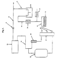
- the separator 10 is of a conventional construction having a filter medium of activated carbon and is conventionally referred to in the automotive industry as the carbon canister.
- the vapour space 11 in the fuel tank 12 communicates the conduit 13 to the input side of the separator 10.
- the check valve 14 located in the conduit 13 is set so as to open and permit a flow of vapour from the fuel tank 12 to the separator 10 when the pressure of the vapour in the fuel tank 12 is more than 10 kPa above the pressure in the separator 10.
- the check valve 17 communicates through the conduit 13 with the vapour space 11 in the fuel tank, and it is set to open if the pressure in the fuel tank 12 falls below atmospheric.
- the outlet side of the separator 10 communicates via the conduit 9 with the air induction passage 15 of the engine downstream of the conventional air box 16 and throttle valve 8 through which the air is drawn into the air induction system of the engine when the engine is in operation.
- vapour will pass from the fuel tank through the separator 10 where the fuel in the vapour will be absorbed by the activated carbon and the treated air will pass into the air induction passage 15. Whilst the engine is running, the air which enters the air induction passage 15 from the separator 10 will form part of the air carried into the engine through the air induction system, and when the engine is not operating, the air passing into the air passage 15 from the separator 10 will be released to atmosphere.
- the compressor 20 draws air from the air box 16 through the conduit 19 and delivers compressed air into the air rail 21 from which air is supplied to the series of fuel injectors 22 to effect delivery of the fuel into the engine combustion chambers.
- the regulator 23 controls the pressure of the air in the air rail 21 and air released by the regulator 23 is returned to the conduit 19 on the intake side of the compressor 20.
- the compressor draws its air supply from the air box 16 into which the cleaned air from the separator 10 is delivered, the proportion of air passing through the air box to the compressor 20 is small compared with the quantity of air passing through the air box 16 and passage 15 into the air induction system of the engine.
- the proportion of air passing through the air box to the compressor 20 is small compared with the quantity of air passing through the air box 16 and passage 15 into the air induction system of the engine.
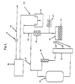
- the present invention proposes to modify the above described system by substituting the conduit 19 as shown in Figure 1 by a conduit 25 as shown in Figure 2, directly connected to the conduit 13 downstream of the check valve 14 and upstream of the separator 10. Fuel vapour discharged from the fuel tank 12 is thus drawn directly into the intake port of the compressor 20. Accordingly, when the engine is operating, the compressor will draw fuel vapour from the fuel tank 12 and additional air as required from the engine air box 16 through the conduit 28 and separator 10, the latter air being drawn in a reverse flow through the separator 10. In the situation where the vapour load from the fuel tank is greater than can be taken by the compressor 20, then the excess vapour will pass through the separator 10 in the conventional manner and be delivered through the conduit 28 into the air induction system of the engine.
- vapour handling system as depicted in Figure 2 is that after a period of shut down of the engine there will be an accumulation of fuel in the active carbon in the separator 10 as previously discussed, but on start up there will be a reverse flow of air from the air induction passage through the separator 10 to the compressor 20. This reverse flow will purge fuel from the active carbon in the separator 10 and that fuel will be subsequently delivered to the engine combustion chamber by the compressor 20, via the air rail 21 and the injectors 22.
- This reverse flow of air through the separator 10 prevents the excess fuel in the separator being drawn directly into the air induction system of the engine, but instead causes the fuel to be delivered to the combustion chamber of the engine through the injectors 22 at a substantially reduced rate so as to not significantly affect the performance of the engine or the level of emissions in the exhaust gas.
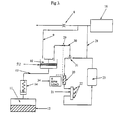
- FIG. 3 is shown a further embodiment of the invention wherein the conduit 30 communicates the separator 10 with the duct 28 which directly communicates the engine air box 16 with the compressor 20.
- a control orifice or venturi 31 is provided in the duct 28 at the junction with the duct 30 so that the duct 30 is under the influence of the sub-atmospheric pressure created in the centre of the venturi 31 as the air passes therethrough from the air box 16 to the compressor 20.
- This arrangement results in the pressure in the duct 30 being substantially directly proportional to the rate of air flow along the duct 28 which is proportional to engine speed.
- the rate of flow of air with or without fuel vapour from the separator 10 into the duct 28 is substantially proportional to the engine speed.
- the venturi 31 the relation between the rate of air flow from the separator to the compressor and engine speed is determinable.
- the location of entry of the fuel free air from the air box 16, and the vapour from the fuel tank 11 to the separator 10 relative to the conduit 30 through which air is drawn from the separator 10 to the compressor 20 are arranged so the air from both the air box and fuel tank pass through the filter media 32 in the separator 10. This arrangement results in the fuel content of the air passing to the compressor being more uniform.
- the filter media function somewhat in the manner of an accumulator for fuel entering from the fuel tank which is subsequently released to the air passing to the compressor.
- the engine management ECU 34 which includes in its function the determination of the fuel demand of the engine can accordingly be programmed so that in determining the fuel requirement of the engine, the ECU will adjust the metered quantity of fuel delivered through the injector in relation to engine speed, to compensate for the quantity of fuel in vapour form supplied with the compressed air that effects injection of the metered quantity of fuel.
- the ECU may be programmed to provide a single correction to the fueling rate for a range of engine speeds as the actual variation of the true correction with that range is small and has an insignificant influence on the engine performance or emission levels.
- an isolating device 29 which may be in the form of a solenoid operated valve, in the separator duct 30.
- the solenoid valve is cyclically operated to open and close the separator duct 30.
- the function of the solenoid valve is to endeavour to obtain under normal operating conditions of the engine, a reasonably steady vapour content in the air being drawn from the separator 10 into the duct 28 leading to the compressor 20.
- the flow of air from the separator 10 to the compressor is cyclically stopped allowing an accumulation of vapour in the separator which will be purged therefrom when the solenoid is next opened.
- the engine management ECU 34 is programmed so that when the solenoid opens and air carrying fuel vapour is passing from the cannister to the compressor, the ECU will make an appropriate adjustment to the metered quantity of fuel delivered by the injector to the engine as previously referred to. However, when the solenoid valve is closed, the engine management ECU will not make any correction to the quantity of metered fuel as there is no fuel being provided in the air from the compressor. It is to be understood that the solenoid may also be operated in a manner whereby there are no fixed open and closed periods, but these periods may be modulated by the engine management ECU subject to engine operating conditions.
Landscapes
- Engineering & Computer Science (AREA)
- Chemical & Material Sciences (AREA)
- Combustion & Propulsion (AREA)
- Mechanical Engineering (AREA)
- General Engineering & Computer Science (AREA)
- Supplying Secondary Fuel Or The Like To Fuel, Air Or Fuel-Air Mixtures (AREA)
- Yarns And Mechanical Finishing Of Yarns Or Ropes (AREA)
- Telephone Function (AREA)
- Fuel-Injection Apparatus (AREA)
- Catalysts (AREA)
- Physical Or Chemical Processes And Apparatus (AREA)
- Electrical Control Of Air Or Fuel Supplied To Internal-Combustion Engine (AREA)
- Processing Of Solid Wastes (AREA)
- Organic Low-Molecular-Weight Compounds And Preparation Thereof (AREA)
- Output Control And Ontrol Of Special Type Engine (AREA)
Applications Claiming Priority (3)
| Application Number | Priority Date | Filing Date | Title |
|---|---|---|---|
| AUPJ882990 | 1990-02-27 | ||
| AU8829/90 | 1990-02-27 | ||
| PCT/AU1991/000065 WO1991013251A1 (en) | 1990-02-27 | 1991-02-27 | Treatment of fuel vapour emissions |
Publications (3)
| Publication Number | Publication Date |
|---|---|
| EP0516684A1 EP0516684A1 (en) | 1992-12-09 |
| EP0516684A4 EP0516684A4 (en) | 1994-10-19 |
| EP0516684B1 true EP0516684B1 (en) | 1997-01-15 |
Family
ID=3774521
Family Applications (1)
| Application Number | Title | Priority Date | Filing Date |
|---|---|---|---|
| EP91904690A Expired - Lifetime EP0516684B1 (en) | 1990-02-27 | 1991-02-27 | Treatment of fuel vapour emissions |
Country Status (12)
| Country | Link |
|---|---|
| US (1) | US5245974A (pl) |
| EP (1) | EP0516684B1 (pl) |
| KR (1) | KR100207764B1 (pl) |
| AT (1) | ATE147835T1 (pl) |
| AU (1) | AU641223B2 (pl) |
| BR (1) | BR9106097A (pl) |
| CA (1) | CA2076015C (pl) |
| DE (1) | DE69124226T2 (pl) |
| HU (1) | HU217041B (pl) |
| PL (1) | PL167652B1 (pl) |
| RU (1) | RU2065528C1 (pl) |
| WO (1) | WO1991013251A1 (pl) |
Families Citing this family (28)
| Publication number | Priority date | Publication date | Assignee | Title |
|---|---|---|---|---|
| US5375578A (en) * | 1992-03-05 | 1994-12-27 | Sanshin Kogyo Kabushiki Kaisha | High pressure fuel feeding device for fuel injection engine |
| FR2704601B1 (fr) * | 1993-04-26 | 1995-07-13 | Renault | Système d'alimentation d'air pour injecteurs de carburant du type à manteau d'air équipant un moteur à combustion interne. |
| AU7734294A (en) * | 1993-09-21 | 1995-04-10 | Orbital Engine Company (Australia) Proprietary Limited | Catalytic treatment of engine exhaust gas |
| US5666927A (en) * | 1996-07-26 | 1997-09-16 | Siemens Automotive Corporation | Fuel/air supply system for a fuel injector and methods of operation |
| FR2759420A1 (fr) * | 1997-02-07 | 1998-08-14 | Siemens Automotive Sa | Procede et dispositif de regeneration d'un filtre a vapeurs de carburant pour un moteur a injection directe |
| US5970957A (en) * | 1998-03-05 | 1999-10-26 | Ford Global Technologies, Inc. | Vapor recovery system |
| AUPP627098A0 (en) | 1998-09-30 | 1998-10-22 | Orbital Engine Company (Australia) Proprietary Limited | Purge fuel flow rate determination method |
| RU2169283C2 (ru) * | 1999-03-12 | 2001-06-20 | Одинцов Анатолий Протокенович | Способ получения "яровизированного" бензина для работы двигателя внутреннего сгорания |
| AUPQ275299A0 (en) * | 1999-09-10 | 1999-10-07 | Orbital Engine Company (Australia) Proprietary Limited | Compressor inlet system |
| US6273072B1 (en) | 2000-02-09 | 2001-08-14 | Paul E. Knapstein | Fuel system apparatus and method |
| DE10007522B4 (de) * | 2000-02-18 | 2006-10-26 | Siemens Ag | Verfahren zur Trennung von Kraftstoffdampf-Luft-Gemischen und Vorrichtung zur Durchführung dieses Verfahrens |
| US6302337B1 (en) | 2000-08-24 | 2001-10-16 | Synerject, Llc | Sealing arrangement for air assist fuel injectors |
| US6484700B1 (en) | 2000-08-24 | 2002-11-26 | Synerject, Llc | Air assist fuel injectors |
| US6402057B1 (en) | 2000-08-24 | 2002-06-11 | Synerject, Llc | Air assist fuel injectors and method of assembling air assist fuel injectors |
| CA2324533A1 (en) | 2000-10-27 | 2002-04-27 | Carl Hunter | Oxygen enrichment in diesel engines |
| US6776144B1 (en) * | 2003-05-28 | 2004-08-17 | Lennox G. Newman | Five stroke internal combustion engine |
| US6880534B2 (en) * | 2003-07-08 | 2005-04-19 | Honda Motor Co., Ltd. | Evaporative fuel processing system |
| KR100579235B1 (ko) * | 2003-10-01 | 2006-05-11 | 현대자동차주식회사 | 가솔린 직접 분사 엔진 시스템 |
| EP1653077B1 (en) * | 2004-10-26 | 2007-07-04 | Ford Global Technologies, LLC | Injector leakage limitation |
| JP2007056840A (ja) * | 2005-08-26 | 2007-03-08 | Yamaha Motor Co Ltd | エンジン装置における燃料タンクの燃料蒸気排出構造 |
| US7373930B1 (en) * | 2007-08-23 | 2008-05-20 | Chrysler Llc | Multi-port check-valve for an evaporative fuel emissions system in a turbocharged vehicle |
| US20100024781A1 (en) * | 2008-07-30 | 2010-02-04 | Jerry Wegendt | Compressed Fuel Supply System |
| US8483934B2 (en) * | 2010-07-19 | 2013-07-09 | Ford Global Technologies, Llc | Method for purging fuel vapors |
| DE102011054851A1 (de) | 2011-10-27 | 2013-05-02 | Dr. Ing. H.C. F. Porsche Aktiengesellschaft | Tankentlüftung mit Venturi-Düse |
| US9243580B2 (en) * | 2011-12-07 | 2016-01-26 | Ford Global Technologies, Llc | Method and system for reducing soot formed by an engine |
| US9222443B2 (en) * | 2012-04-11 | 2015-12-29 | Ford Global Technologies, Llc | Method for purging fuel vapors to an engine |
| CA2868338C (en) * | 2014-10-23 | 2016-01-12 | Westport Power Inc. | Gaseous fuel vent handling apparatus and method |
| US9964080B2 (en) * | 2016-08-25 | 2018-05-08 | Ford Global Technologies, Llc | Method and system for vacuum generation using a throttle |
Family Cites Families (11)
| Publication number | Priority date | Publication date | Assignee | Title |
|---|---|---|---|---|
| US4376423A (en) * | 1981-06-08 | 1983-03-15 | William C. Knapstein | Method and apparatus for saturating a liquid fuel with a gas and an internal combustion engine |
| JPS58110852A (ja) * | 1981-12-25 | 1983-07-01 | Honda Motor Co Ltd | 過給機付内燃機関における蒸発燃料制御装置 |
| JPS58110853A (ja) * | 1981-12-25 | 1983-07-01 | Honda Motor Co Ltd | 過給機付内燃機関における蒸発燃料制御装置 |
| JPS58155269A (ja) * | 1981-12-31 | 1983-09-14 | オ−ビタル・エンジン・カンパニイ・プロプライエタリ・リミテイツド | エンジンにガス圧により液体燃料を供給する方法及びその装置 |
| CA1279797C (en) * | 1984-08-01 | 1991-02-05 | Michael Leonard Mckay | Metering of fuel |
| WO1987002419A1 (en) * | 1985-10-11 | 1987-04-23 | Orbital Engine Company Proprietary Limited | Differential pressure fuel/air metering device |
| US4962745A (en) * | 1988-10-04 | 1990-10-16 | Toyota Jidosha Kabushiki Kaisha | Fuel supply device of an engine |
| US5054454A (en) * | 1989-11-09 | 1991-10-08 | Ford Motor Company | Fuel vapor recovery control system |
| US5005550A (en) * | 1989-12-19 | 1991-04-09 | Chrysler Corporation | Canister purge for turbo engine |
| US5190015A (en) * | 1991-02-05 | 1993-03-02 | Toyota Jidosha Kabushiki Kaisha | Evaporated fuel discharge suppressing apparatus for an internal combustion engine |
| US5138023A (en) * | 1991-10-11 | 1992-08-11 | Exxon Research And Engineering Company | Unsaturated polyesters and crosslinked membranes therefrom for aromatics/saturates separation |
-
1991
- 1991-02-27 EP EP91904690A patent/EP0516684B1/en not_active Expired - Lifetime
- 1991-02-27 KR KR1019920702040A patent/KR100207764B1/ko not_active Expired - Fee Related
- 1991-02-27 PL PL91295864A patent/PL167652B1/pl unknown
- 1991-02-27 RU SU915052960A patent/RU2065528C1/ru not_active IP Right Cessation
- 1991-02-27 CA CA002076015A patent/CA2076015C/en not_active Expired - Fee Related
- 1991-02-27 AT AT91904690T patent/ATE147835T1/de not_active IP Right Cessation
- 1991-02-27 WO PCT/AU1991/000065 patent/WO1991013251A1/en not_active Ceased
- 1991-02-27 HU HU9202759A patent/HU217041B/hu not_active IP Right Cessation
- 1991-02-27 BR BR919106097A patent/BR9106097A/pt not_active IP Right Cessation
- 1991-02-27 US US07/923,781 patent/US5245974A/en not_active Expired - Fee Related
- 1991-02-27 DE DE69124226T patent/DE69124226T2/de not_active Expired - Fee Related
- 1991-02-27 AU AU73049/91A patent/AU641223B2/en not_active Ceased
Also Published As
| Publication number | Publication date |
|---|---|
| CA2076015A1 (en) | 1991-08-28 |
| HU9202759D0 (en) | 1992-12-28 |
| HUT66810A (en) | 1995-01-30 |
| KR920703993A (ko) | 1992-12-18 |
| WO1991013251A1 (en) | 1991-09-05 |
| DE69124226D1 (de) | 1997-02-27 |
| CA2076015C (en) | 2000-10-24 |
| ATE147835T1 (de) | 1997-02-15 |
| KR100207764B1 (ko) | 1999-07-15 |
| BR9106097A (pt) | 1993-02-24 |
| HU217041B (hu) | 1999-11-29 |
| US5245974A (en) | 1993-09-21 |
| DE69124226T2 (de) | 1997-06-05 |
| AU641223B2 (en) | 1993-09-16 |
| EP0516684A4 (en) | 1994-10-19 |
| AU7304991A (en) | 1991-09-18 |
| PL167652B1 (pl) | 1995-10-31 |
| RU2065528C1 (ru) | 1996-08-20 |
| EP0516684A1 (en) | 1992-12-09 |
Similar Documents
| Publication | Publication Date | Title |
|---|---|---|
| EP0516684B1 (en) | Treatment of fuel vapour emissions | |
| US4116184A (en) | Apparatus for treating evaporated fuel gas | |
| US5272873A (en) | Evaporative emission control system for internal combustion engines | |
| US6446618B1 (en) | Purge fuel flow rate determination method | |
| US20090044785A1 (en) | Vehicle, In Particular A Motor Vehicle With A Tank Ventilation System | |
| US3610221A (en) | Fuel tank purge system and method | |
| US5335638A (en) | Evaporated fuel controller | |
| US10774791B2 (en) | Method for increasing the quantity of purging air in the tank venting system by completely blocking the injection of at least one cylinder | |
| US6155239A (en) | Fuel vapor system | |
| US4137879A (en) | Exhaust gas recirculation means | |
| US5375579A (en) | Evaporated fuel controller | |
| US5273018A (en) | Evaporation fuel control apparatus of engine | |
| US5791321A (en) | Fuel supplying apparatus for internal combustion engine | |
| US5269279A (en) | Evaporating fuel control device for vehicles | |
| US5893353A (en) | Evaporative fuel controller for internal combustion engine | |
| JP3014447B2 (ja) | 燃料蒸気エミッションの処理 | |
| JP2020112121A (ja) | 蒸発燃料処理装置 | |
| US20190345899A1 (en) | Vaporized-fuel treating apparatus | |
| US20200173398A1 (en) | Method and device for tank ventilation of a fuel tank of a vehicle | |
| JPS60175757A (ja) | 内燃機関の蒸発燃料制御装置 | |
| KR0113601Y1 (ko) | 자동차의 증발가스 제어 장치 | |
| JPH0510218A (ja) | エバポ装置 | |
| JPS6113735Y2 (pl) | ||
| JPS5847239Y2 (ja) | エンジンの蒸発燃料処理装置 | |
| JPH0626386A (ja) | エンジンの空燃比制御装置 |
Legal Events
| Date | Code | Title | Description |
|---|---|---|---|
| PUAI | Public reference made under article 153(3) epc to a published international application that has entered the european phase |
Free format text: ORIGINAL CODE: 0009012 |
|
| 17P | Request for examination filed |
Effective date: 19920820 |
|
| AK | Designated contracting states |
Kind code of ref document: A1 Designated state(s): AT BE CH DE DK ES FR GB GR IT LI LU NL SE |
|
| A4 | Supplementary search report drawn up and despatched | ||
| AK | Designated contracting states |
Kind code of ref document: A4 Designated state(s): AT BE CH DE DK ES FR GB GR IT LI LU NL SE |
|
| 17Q | First examination report despatched |
Effective date: 19950925 |
|
| GRAG | Despatch of communication of intention to grant |
Free format text: ORIGINAL CODE: EPIDOS AGRA |
|
| GRAH | Despatch of communication of intention to grant a patent |
Free format text: ORIGINAL CODE: EPIDOS IGRA |
|
| GRAH | Despatch of communication of intention to grant a patent |
Free format text: ORIGINAL CODE: EPIDOS IGRA |
|
| GRAA | (expected) grant |
Free format text: ORIGINAL CODE: 0009210 |
|
| AK | Designated contracting states |
Kind code of ref document: B1 Designated state(s): AT BE CH DE DK ES FR GB GR IT LI LU NL SE |
|
| PG25 | Lapsed in a contracting state [announced via postgrant information from national office to epo] |
Ref country code: IT Free format text: LAPSE BECAUSE OF FAILURE TO SUBMIT A TRANSLATION OF THE DESCRIPTION OR TO PAY THE FEE WITHIN THE PRE;WARNING: LAPSES OF ITALIAN PATENTS WITH EFFECTIVE DATE BEFORE 2007 MAY HAVE OCCURRED AT ANY TIME BEFORE 2007. THE CORRECT EFFECTIVE DATE MAY BE DIFFERENT FROM THE ONE RECORDED.SCRIBED TIME-LIMIT Effective date: 19970115 Ref country code: NL Free format text: LAPSE BECAUSE OF FAILURE TO SUBMIT A TRANSLATION OF THE DESCRIPTION OR TO PAY THE FEE WITHIN THE PRESCRIBED TIME-LIMIT Effective date: 19970115 Ref country code: AT Effective date: 19970115 Ref country code: GR Free format text: LAPSE BECAUSE OF FAILURE TO SUBMIT A TRANSLATION OF THE DESCRIPTION OR TO PAY THE FEE WITHIN THE PRESCRIBED TIME-LIMIT Effective date: 19970115 Ref country code: LI Free format text: LAPSE BECAUSE OF FAILURE TO SUBMIT A TRANSLATION OF THE DESCRIPTION OR TO PAY THE FEE WITHIN THE PRESCRIBED TIME-LIMIT Effective date: 19970115 Ref country code: DK Effective date: 19970115 Ref country code: CH Free format text: LAPSE BECAUSE OF FAILURE TO SUBMIT A TRANSLATION OF THE DESCRIPTION OR TO PAY THE FEE WITHIN THE PRESCRIBED TIME-LIMIT Effective date: 19970115 |
|
| REF | Corresponds to: |
Ref document number: 147835 Country of ref document: AT Date of ref document: 19970215 Kind code of ref document: T |
|
| REG | Reference to a national code |
Ref country code: CH Ref legal event code: EP |
|
| PGFP | Annual fee paid to national office [announced via postgrant information from national office to epo] |
Ref country code: AT Payment date: 19970129 Year of fee payment: 7 |
|
| PGFP | Annual fee paid to national office [announced via postgrant information from national office to epo] |
Ref country code: DK Payment date: 19970212 Year of fee payment: 7 |
|
| PGFP | Annual fee paid to national office [announced via postgrant information from national office to epo] |
Ref country code: SE Payment date: 19970217 Year of fee payment: 7 |
|
| PGFP | Annual fee paid to national office [announced via postgrant information from national office to epo] |
Ref country code: ES Payment date: 19970227 Year of fee payment: 7 Ref country code: NL Payment date: 19970227 Year of fee payment: 7 |
|
| REF | Corresponds to: |
Ref document number: 69124226 Country of ref document: DE Date of ref document: 19970227 |
|
| PGFP | Annual fee paid to national office [announced via postgrant information from national office to epo] |
Ref country code: LU Payment date: 19970327 Year of fee payment: 7 |
|
| PGFP | Annual fee paid to national office [announced via postgrant information from national office to epo] |
Ref country code: BE Payment date: 19970410 Year of fee payment: 7 |
|
| PG25 | Lapsed in a contracting state [announced via postgrant information from national office to epo] |
Ref country code: SE Effective date: 19970415 |
|
| ET | Fr: translation filed | ||
| NLV1 | Nl: lapsed or annulled due to failure to fulfill the requirements of art. 29p and 29m of the patents act | ||
| PG25 | Lapsed in a contracting state [announced via postgrant information from national office to epo] |
Ref country code: ES Free format text: LAPSE BECAUSE OF FAILURE TO SUBMIT A TRANSLATION OF THE DESCRIPTION OR TO PAY THE FEE WITHIN THE PRESCRIBED TIME-LIMIT Effective date: 19970723 |
|
| REG | Reference to a national code |
Ref country code: CH Ref legal event code: PL |
|
| PLBE | No opposition filed within time limit |
Free format text: ORIGINAL CODE: 0009261 |
|
| STAA | Information on the status of an ep patent application or granted ep patent |
Free format text: STATUS: NO OPPOSITION FILED WITHIN TIME LIMIT |
|
| 26N | No opposition filed | ||
| PG25 | Lapsed in a contracting state [announced via postgrant information from national office to epo] |
Ref country code: LU Free format text: LAPSE BECAUSE OF NON-PAYMENT OF DUE FEES Effective date: 19980227 |
|
| PG25 | Lapsed in a contracting state [announced via postgrant information from national office to epo] |
Ref country code: BE Free format text: LAPSE BECAUSE OF NON-PAYMENT OF DUE FEES Effective date: 19980228 |
|
| BERE | Be: lapsed |
Owner name: ORBITAL ENGINE CY (AUSTRALIA) PTY. LTD Effective date: 19980228 |
|
| REG | Reference to a national code |
Ref country code: GB Ref legal event code: IF02 |
|
| PGFP | Annual fee paid to national office [announced via postgrant information from national office to epo] |
Ref country code: GB Payment date: 20040225 Year of fee payment: 14 |
|
| PG25 | Lapsed in a contracting state [announced via postgrant information from national office to epo] |
Ref country code: GB Free format text: LAPSE BECAUSE OF NON-PAYMENT OF DUE FEES Effective date: 20050227 |
|
| GBPC | Gb: european patent ceased through non-payment of renewal fee |
Effective date: 20050227 |
|
| PGFP | Annual fee paid to national office [announced via postgrant information from national office to epo] |
Ref country code: DE Payment date: 20070222 Year of fee payment: 17 |
|
| PGFP | Annual fee paid to national office [announced via postgrant information from national office to epo] |
Ref country code: FR Payment date: 20070208 Year of fee payment: 17 |
|
| REG | Reference to a national code |
Ref country code: FR Ref legal event code: ST Effective date: 20081031 |
|
| PG25 | Lapsed in a contracting state [announced via postgrant information from national office to epo] |
Ref country code: DE Free format text: LAPSE BECAUSE OF NON-PAYMENT OF DUE FEES Effective date: 20080902 |
|
| PG25 | Lapsed in a contracting state [announced via postgrant information from national office to epo] |
Ref country code: FR Free format text: LAPSE BECAUSE OF NON-PAYMENT OF DUE FEES Effective date: 20080229 |