EP0514291A2 - Futtervorrichtung für Wassertiere - Google Patents
Futtervorrichtung für Wassertiere Download PDFInfo
- Publication number
- EP0514291A2 EP0514291A2 EP92420147A EP92420147A EP0514291A2 EP 0514291 A2 EP0514291 A2 EP 0514291A2 EP 92420147 A EP92420147 A EP 92420147A EP 92420147 A EP92420147 A EP 92420147A EP 0514291 A2 EP0514291 A2 EP 0514291A2
- Authority
- EP
- European Patent Office
- Prior art keywords
- casing
- aforementioned
- housing
- opening
- zone
- Prior art date
- Legal status (The legal status is an assumption and is not a legal conclusion. Google has not performed a legal analysis and makes no representation as to the accuracy of the status listed.)
- Withdrawn
Links
Images


Classifications
-
- A—HUMAN NECESSITIES
- A01—AGRICULTURE; FORESTRY; ANIMAL HUSBANDRY; HUNTING; TRAPPING; FISHING
- A01K—ANIMAL HUSBANDRY; AVICULTURE; APICULTURE; PISCICULTURE; FISHING; REARING OR BREEDING ANIMALS, NOT OTHERWISE PROVIDED FOR; NEW BREEDS OF ANIMALS
- A01K61/00—Culture of aquatic animals
- A01K61/80—Feeding devices
- A01K61/85—Feeding devices for use with aquaria
-
- Y—GENERAL TAGGING OF NEW TECHNOLOGICAL DEVELOPMENTS; GENERAL TAGGING OF CROSS-SECTIONAL TECHNOLOGIES SPANNING OVER SEVERAL SECTIONS OF THE IPC; TECHNICAL SUBJECTS COVERED BY FORMER USPC CROSS-REFERENCE ART COLLECTIONS [XRACs] AND DIGESTS
- Y02—TECHNOLOGIES OR APPLICATIONS FOR MITIGATION OR ADAPTATION AGAINST CLIMATE CHANGE
- Y02A—TECHNOLOGIES FOR ADAPTATION TO CLIMATE CHANGE
- Y02A40/00—Adaptation technologies in agriculture, forestry, livestock or agroalimentary production
- Y02A40/80—Adaptation technologies in agriculture, forestry, livestock or agroalimentary production in fisheries management
- Y02A40/81—Aquaculture, e.g. of fish
Definitions
- the present invention relates to an apparatus for distributing food for aquatic fauna and more particularly to an apparatus for distributing food on the surface of water in an aquarium.
- the dispensers currently in use generally present problems of use and problems linked to the humid atmosphere existing above the surface of the water.
- the present invention aims to remedy these drawbacks in particular.
- the food distribution apparatus comprises a casing in which are arranged transfer means, in particular a worm screw arranged in a channel of the casing, of the food from a departure zone to an evacuation zone with which an access opening and an outlet opening of the casing are associated.
- the casing preferably has, at the periphery of its access opening, complementary coupling means of coupling means provided on a box constituting a food reserve and having an opening communicating with the aforementioned starting zone when this box is coupled to the housing.
- said coupling means are preferably constituted by complementary threads.
- said access opening of the casing can advantageously be turned upwards, so that the aforementioned box can be mounted upside down.
- the casing preferably has a cylindrical zone surrounding the aforementioned worm.
- the device preferably comprises a movable valve adapted to close the abovementioned discharge opening of the casing.
- said valve is formed by a rotary member secured to the aforementioned worm.
- the aforementioned discharge opening of the casing is formed in the lower part of a cylindrical part of the casing, said valve having a cylindrical part surrounding or engaged in the above cylindrical part of the casing and in which is formed an opening capable of coming by rotation in correspondence with the discharge opening of the casing.
- said valve can advantageously have a radial wall carrying one of the ends of the aforementioned worm.
- said casing is preferably removably mounted on a support, this casing and this support having reciprocal positioning means.
- said support can advantageously have a housing containing motor means having an output shaft, this output shaft and one of the ends of the aforementioned worm having reciprocal coupling means by contact.
- said positioning means can be constituted by walls of the casing and of the support which extend perpendicular to the axis of the aforementioned worm, the aforementioned output shaft having a lateral slot in which s engages the aforementioned end of the worm.
- the volume of the aforementioned channel is preferably greater than the enveloping volume of the worm.
- the aforementioned support preferably has means for fixing to the upper edge of a vertical wall of an aquarium.
- said fixing means are formed by a slot or groove in said support and play take-up means.
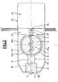
- the dispensing device shown in the figures and generally identified by the reference 1 comprises a housing generally identified by the reference 2 which has a horizontal channel 3 in which extends a horizontal worm 4 whose end portions 5 and 6 extend respectively through a rear wall 7 of the casing 2 and through a radial wall 8 of a valve generally identified by the reference 9 that the we will describe later.
- the casing 2 has, on the side of its rear radial wall 7, a cylindrical wall 10 projecting upwards which determines an access opening 11 to a starting zone 12 of the channel 3.
- the cylindrical part 10 of the casing 2 is engaged the cylindrical end 13 of a cylindrical box 14 mounted upside down and constituting a food reserve 15.
- the part 10 of the casing 2 and the cylindrical end 13 of the box 14 have complementary screw pitches 10a and 13a for fixing.
- the casing 2 On the side of the radial wall 8 of the valve 9, the casing 2 has a cylindrical wall 16 whose diameter is slightly greater than that of the worm 4 and which determines a discharge area 17.
- this wall 16 has an opening 18.
- the casing 2 has a cylindrical part 19 which closely surrounds the worm screw 4 and which extends over a length at least equal to one revolution of the thread of the worm screw end 4 to thereby form a middle zone 20 of channel 3.
- the valve 9 has, from its radial wall 8 which is integral with the worm 4 by any known means, a cylindrical part 21 which envelops the cylindrical part 16 of the casing 2.
- This cylindrical part 21 has an opening in its wall 22 which, when it is opposite the lower discharge opening 18 of the casing 2, has the same dimension.
- the device 1 further comprises a support generally identified by the reference 23 which has on the one hand a parallelepipedic housing 24 and on the other hand a platform 25 which extends laterally to one of the walls vertical 26 of this housing 24.
- the platform 5 has, starting from the wall 26 of the housing 24 and successively, a horizontal wall 27, a vertical wall 28 which extends downwards, a horizontal wall 29 which moves away from the wall 26 of the housing 24 and a front wall 30 which extends vertically and upwards, the horizontal wall 29 having lateral edges 29a and 29b extending upwards.
- This form of the platform 25 is intended to receive by engagement from above the casing 2 in the following manner.
- the outer face of the radial part 8 of the valve 9 secured to the casing 2 is in contact with the inner face of the end wall 30 of the platform 25, the projecting end 6 of the worm 4 being engaged vertically at the bottom of a recess 31 formed in the upper edge of the latter.
- the rear wall 7 of the casing 2 is extended downwards by a wall 32 which is in contact with the internal face of the vertical wall 28 of the platform 25.
- the casing 2 has an annular vertical wall 33 which is engaged vertically in an annular part 33a of the horizontal wall 29 of the platform 25, this annular part 33a projecting upwards.
- the lower end of the projecting part 33 is in abutment on the upper face of the horizontal wall 29 of the platform 25.
- the casing 2 is removably mounted on the platform 25 of the support 23 in a position such that the endless screw 4 extends horizontally, perpendicular to the vertical wall 26 of the housing 24, the projecting end 5 of this endless screw 4 extending above and at a distance from the horizontal wall 27 of the platform 25.
- the housing 24 contains a geared motor assembly 34 which has an output shaft 35 which extends through its vertical wall 26 and which has a slot 37 opening out at its end and laterally, in which the end 5 of the worm 4, the latter having two opposite parallel flats coming into contact with the opposite parallel faces of this recess 37.
- the shaft 35 is coupled to the worm 4, the latter being in alignment.
- the vertical wall 28 of the platform 25 and the lower part of the vertical wall 26 of the housing 24 determine between them and below the horizontal wall 27 of the platform 26, a transverse groove or slot 38 in which is engaged the upper edge of a vertical wall 39 of an aquarium not shown elsewhere, thanks to the play and gripping screws 40 provided on the support 23, the upper edge of this wall 39 can be pinched and the support 23 suitably maintained, the platform 25 carrying the casing 2 extending above and at a distance from the water contained in the aquarium while the housing 24 is outside.
- the horizontal wall 29 of the platform 25 has a large opening 41 provided below the discharge opening 18 of the casing 2 and the underside of the wall 29 of the platform 25 and the underside of the housing 24, which are in the same horizontal plane, are provided with suction cups 42 which constitute another means of fixing the apparatus 1 to, for example, an upper horizontal wall of an aquarium.
- the food dispensing apparatus 1 described above can be used and operates as follows.
- the endless screw 4 rotates the valve 9.
- the cylindrical wall 21 of this valve 9 moves in front of the discharge opening 18 of the casing 2
- the food 15 collects in the area of discharge 17 from channel 3 delimited at its periphery by the cylindrical wall 16 of the casing 2.
- the opening 22 of the cylindrical wall 21 of the valve 9 discovers the discharge opening 18 of the casing 2
- the food falls by gravity and under the effect of the worm 4, passes through the opening 41 of the horizontal wall 29 of the platform 25 and spreads over the upper face of the water contained in the aquarium to which the apparatus 1 is fixed.
- the geared motor assembly 34 of the device 1 is subjected to an electrical or electronic control assembly, not shown, which allows the worm 4 to stop in a position such that the opening 22 of the valve 9 is not opposite the discharge opening 18 of the casing 2 and the slot 37 of the output shaft 35 is open upwards.
- This control assembly is preferably adapted to rotate the worm screw 4 at times spaced and to rotate it each time by a predetermined number of turns, this time and this number being preferably programmable by the user.
- the food contained in the casing 2 and in the box 14 is isolated from the ambient air which, above the water, is humid. This result is obtained on the one hand by the valve 9 and on the other hand by the food which is in the middle zone 20 of the casing 2 separating the starting zone 12 and the evacuation zone 17 of the channel 3.
- the device 1 is therefore unlikely to become clogged.
- the housing 24 is not above water and therefore experiences less moisture.
- the apparatus 1 being in the stop position described above, the casing 2 of the platform 25 of the support 23 and the end of the worm screw 4 of the shaft 35 are uncoupled by pulling the casing 2 towards the high.
- the casing 2 is overturned and the box 14 is uncoupled by unscrewing it.
- the new box 14 being coupled to the casing 2, the latter is overturned so that the new box 14 extends above and the casing 2 is re-coupled to the platform 25 of the support 23 and the worm 4 to the output shaft 25 by engaging it from above and vertically until it stops on the platform 25.
- the device 1 is again ready to operate as described above.
Landscapes
- Life Sciences & Earth Sciences (AREA)
- Environmental Sciences (AREA)
- Marine Sciences & Fisheries (AREA)
- Zoology (AREA)
- Animal Husbandry (AREA)
- Biodiversity & Conservation Biology (AREA)
- Feeding And Watering For Cattle Raising And Animal Husbandry (AREA)
- Farming Of Fish And Shellfish (AREA)
Applications Claiming Priority (2)
| Application Number | Priority Date | Filing Date | Title |
|---|---|---|---|
| FR9105969A FR2676329A1 (fr) | 1991-05-16 | 1991-05-16 | Appareil de distribution de nourriture pour faune aquatique. |
| FR9105969 | 1991-05-16 |
Publications (2)
| Publication Number | Publication Date |
|---|---|
| EP0514291A2 true EP0514291A2 (de) | 1992-11-19 |
| EP0514291A3 EP0514291A3 (en) | 1993-06-30 |
Family
ID=9412852
Family Applications (1)
| Application Number | Title | Priority Date | Filing Date |
|---|---|---|---|
| EP19920420147 Withdrawn EP0514291A3 (en) | 1991-05-16 | 1992-05-07 | Food dispenser for aquatic live |
Country Status (4)
| Country | Link |
|---|---|
| EP (1) | EP0514291A3 (de) |
| JP (1) | JPH05153883A (de) |
| CA (1) | CA2068698A1 (de) |
| FR (1) | FR2676329A1 (de) |
Cited By (6)
| Publication number | Priority date | Publication date | Assignee | Title |
|---|---|---|---|---|
| EP2845474A3 (de) * | 2013-09-10 | 2015-03-25 | Pet Mate Limited | Futtervorrichtung |
| EP2923566A3 (de) * | 2014-03-25 | 2015-12-02 | Mink Papir A/S | Motorisiertes Fütterungsfahrzeug und Verfahren zum Betrieb eines Tierhaltungssystems |
| US9295226B2 (en) | 2010-01-15 | 2016-03-29 | Pet Mate Ltd. | Battery-powered animal feeder having improved metering |
| WO2017157722A1 (en) * | 2016-03-18 | 2017-09-21 | Tetra Gmbh | Feeding apparatus and method for operating a feeding apparatus |
| CN110521658A (zh) * | 2019-10-08 | 2019-12-03 | 苏州韵之秋智能科技有限公司 | 一种用于水族箱的大型热带鱼投食系统及投食方法 |
| CN118415119A (zh) * | 2024-03-29 | 2024-08-02 | 沈阳航天新光集团有限公司 | 一种关联角度的变量饵料投放装置 |
Families Citing this family (6)
| Publication number | Priority date | Publication date | Assignee | Title |
|---|---|---|---|---|
| JP2010287795A (ja) * | 2009-06-12 | 2010-12-24 | Sharp Corp | 太陽電池モジュールおよびこれを搭載した電子部品、電気部品、電子機器 |
| CN106359152A (zh) * | 2016-08-31 | 2017-02-01 | 南宁丰优农业科技有限公司 | 一种动物饲养用干饲料喂食回收系统 |
| CN107125151A (zh) * | 2017-07-07 | 2017-09-05 | 张迪超 | 一种生猪养殖用饲料投喂装置 |
| CN107278940B (zh) * | 2017-08-10 | 2018-10-19 | 诸暨市志缇生物科技有限公司 | 一种饲料投喂机 |
| CN107278939A (zh) * | 2017-08-10 | 2017-10-24 | 朱澎锋 | 一种养殖用饲料投喂机 |
| CN117397587B (zh) * | 2023-11-21 | 2024-05-28 | 青岛法牧机械有限公司 | 一种具有通风降温功能的畜禽养殖舍 |
Family Cites Families (9)
| Publication number | Priority date | Publication date | Assignee | Title |
|---|---|---|---|---|
| US2700489A (en) * | 1951-06-18 | 1955-01-25 | Sheft Matthew John | Rotatably mounted dispenser for granular material in measured quantities |
| US3113556A (en) * | 1962-04-18 | 1963-12-10 | Decor Sound Corp | Fish feeder |
| JPS4935693B1 (de) * | 1970-09-09 | 1974-09-25 | ||
| US3738328A (en) * | 1972-02-07 | 1973-06-12 | Appleton A | Fish feeder |
| US4296710A (en) * | 1980-04-08 | 1981-10-27 | Sillers Iii William M | Automatic feeding apparatus |
| FR2560498B1 (fr) * | 1984-03-05 | 1986-12-05 | Lecompere Jean | Distributeur automatique de nourriture |
| US4706849A (en) * | 1986-08-08 | 1987-11-17 | Ryan Michael C | Device for dispensing a pet food from a sealed can container therefor |
| GB2207331A (en) * | 1987-06-23 | 1989-02-01 | Sealand Ind Co Ltd | Fish food dispenser |
| NO881290L (no) * | 1988-03-24 | 1989-09-25 | Alcatel Stk As | Mateanlegg. |
-
1991
- 1991-05-16 FR FR9105969A patent/FR2676329A1/fr not_active Withdrawn
-
1992
- 1992-05-07 EP EP19920420147 patent/EP0514291A3/fr not_active Withdrawn
- 1992-05-14 CA CA002068698A patent/CA2068698A1/fr not_active Abandoned
- 1992-05-15 JP JP4122310A patent/JPH05153883A/ja not_active Withdrawn
Cited By (10)
| Publication number | Priority date | Publication date | Assignee | Title |
|---|---|---|---|---|
| US9295226B2 (en) | 2010-01-15 | 2016-03-29 | Pet Mate Ltd. | Battery-powered animal feeder having improved metering |
| EP2845474A3 (de) * | 2013-09-10 | 2015-03-25 | Pet Mate Limited | Futtervorrichtung |
| GB2519654A (en) * | 2013-09-10 | 2015-04-29 | Pet Mate Ltd | Feeder |
| GB2519654B (en) * | 2013-09-10 | 2015-11-11 | Pet Mate Ltd | Feeder |
| US9521828B2 (en) | 2013-09-10 | 2016-12-20 | Pet Mate Ltd. | Feeder for animals selected from domestic pets, cage birds, chickens, fish and wild birds |
| EP2923566A3 (de) * | 2014-03-25 | 2015-12-02 | Mink Papir A/S | Motorisiertes Fütterungsfahrzeug und Verfahren zum Betrieb eines Tierhaltungssystems |
| WO2017157722A1 (en) * | 2016-03-18 | 2017-09-21 | Tetra Gmbh | Feeding apparatus and method for operating a feeding apparatus |
| US11617355B2 (en) | 2016-03-18 | 2023-04-04 | Tetra Gmbh | Feeding apparatus and method for operating a feeding apparatus |
| CN110521658A (zh) * | 2019-10-08 | 2019-12-03 | 苏州韵之秋智能科技有限公司 | 一种用于水族箱的大型热带鱼投食系统及投食方法 |
| CN118415119A (zh) * | 2024-03-29 | 2024-08-02 | 沈阳航天新光集团有限公司 | 一种关联角度的变量饵料投放装置 |
Also Published As
| Publication number | Publication date |
|---|---|
| CA2068698A1 (fr) | 1992-11-17 |
| FR2676329A1 (fr) | 1992-11-20 |
| JPH05153883A (ja) | 1993-06-22 |
| EP0514291A3 (en) | 1993-06-30 |
Similar Documents
| Publication | Publication Date | Title |
|---|---|---|
| EP0514291A2 (de) | Futtervorrichtung für Wassertiere | |
| EP0452214B1 (de) | Kaffeemühle und Kaffeemaschine mit solcher Mühle | |
| CH645595A5 (fr) | Appareil distributeur automatique de boissons. | |
| FR2586922A1 (fr) | Mixeur cuiseur a vapeur | |
| FR2726456A1 (fr) | Dispositif de blocage d'une cuve sur un support moteur pour appareil de preparation des aliments | |
| EP0951825A1 (de) | Geflügelfütterer, insbesondere zur Anwendung in einer Geflügelfütterungsanlage | |
| EP0151377A1 (de) | Vorrichtung zum Füllen von Zigarettenpapierhülsen | |
| EP0124458B1 (de) | Spülvorrichtung für einen Spülkasten zu Betätigen durch einen Druckknopf | |
| FR2554263A1 (fr) | Distributeur automatique de bouteilles de gaz, notamment de bouteilles de gaz butane a usage domestique | |
| EP0253032A1 (de) | Konstruktionsmaterialienschneidemaschine | |
| FR2486365A1 (fr) | Dispositif destine a l'extraction et a la distribution des jus de fruits frais | |
| FR2544184A1 (fr) | Machine a cafe | |
| EP0322269A1 (de) | Automatische Ausgabevorrichtung für Beutel | |
| EP0221830A1 (de) | Von Hand bediente automatische Fahrkartenausgabevorrichtung | |
| FR2902295A1 (fr) | Procede et dispositif pour fabriquer des cigarettes par remplissage de tubes en papier avec du tabac. | |
| FR3094780A1 (fr) | Appareil de stockage de produits alimentaires | |
| FR2696330A1 (fr) | Dispositif de distribution et de dosage automatique de produits alimentaires. | |
| EP0128847B1 (de) | Mechanismus zum Umkehren von Bewegungen und seine Anwendung für Dränagevorrichtungen für Spülbecken | |
| BE888877A (fr) | Dispositif de distribution de poudre de cafe | |
| FR2538933A1 (fr) | Dispositif trieur et/ou compteur de pieces de monnaie | |
| FR2804143A1 (fr) | Dispositif de garnissage pour couvercle de reservoir de chasse d'eau et reservoir de chasse d'eau correspondant | |
| FR2684705A1 (fr) | Dispositif de chasse d'eau. | |
| FR1406085A (fr) | Distributeur d'olives | |
| FR2670755A1 (fr) | Recipient distributeur de matieres liquides ou cremeuses. | |
| FR2782260A1 (fr) | Dispositif permettant de raper manuellement le fromage destine a cet effet |
Legal Events
| Date | Code | Title | Description |
|---|---|---|---|
| PUAI | Public reference made under article 153(3) epc to a published international application that has entered the european phase |
Free format text: ORIGINAL CODE: 0009012 |
|
| AK | Designated contracting states |
Kind code of ref document: A2 Designated state(s): AT BE CH DE DK ES GB IT LI NL SE |
|
| PUAL | Search report despatched |
Free format text: ORIGINAL CODE: 0009013 |
|
| AK | Designated contracting states |
Kind code of ref document: A3 Designated state(s): AT BE CH DE DK ES GB IT LI NL SE |
|
| 17P | Request for examination filed |
Effective date: 19931222 |
|
| 17Q | First examination report despatched |
Effective date: 19940525 |
|
| 18D | Application deemed to be withdrawn |
Effective date: 19940805 |