EP0512159B1 - Machine à meuler les rails - Google Patents
Machine à meuler les rails Download PDFInfo
- Publication number
- EP0512159B1 EP0512159B1 EP91119922A EP91119922A EP0512159B1 EP 0512159 B1 EP0512159 B1 EP 0512159B1 EP 91119922 A EP91119922 A EP 91119922A EP 91119922 A EP91119922 A EP 91119922A EP 0512159 B1 EP0512159 B1 EP 0512159B1
- Authority
- EP
- European Patent Office
- Prior art keywords
- frame
- base frame
- frame part
- disposed
- track
- Prior art date
- Legal status (The legal status is an assumption and is not a legal conclusion. Google has not performed a legal analysis and makes no representation as to the accuracy of the status listed.)
- Expired - Lifetime
Links
- 230000006978 adaptation Effects 0.000 description 1
- 238000010409 ironing Methods 0.000 description 1
- 238000000034 method Methods 0.000 description 1
- 230000000149 penetrating effect Effects 0.000 description 1
- 230000006641 stabilisation Effects 0.000 description 1
- 238000011105 stabilization Methods 0.000 description 1
Images

Classifications
-
- E—FIXED CONSTRUCTIONS
- E01—CONSTRUCTION OF ROADS, RAILWAYS, OR BRIDGES
- E01B—PERMANENT WAY; PERMANENT-WAY TOOLS; MACHINES FOR MAKING RAILWAYS OF ALL KINDS
- E01B31/00—Working rails, sleepers, baseplates, or the like, in or on the line; Machines, tools, or auxiliary devices specially designed therefor
- E01B31/02—Working rail or other metal track components on the spot
- E01B31/12—Removing metal from rails, rail joints, or baseplates, e.g. for deburring welds, reconditioning worn rails
- E01B31/17—Removing metal from rails, rail joints, or baseplates, e.g. for deburring welds, reconditioning worn rails by grinding
- E01B31/175—Removing metal from rails, rail joints, or baseplates, e.g. for deburring welds, reconditioning worn rails by grinding using grinding belts
Definitions
- the invention relates to a rail grinding machine according to the preamble of claim 1.
- a corresponding rail grinding machine is known from EP-A-0 110 246.
- the machine described there has a machine frame pivotably connected to a chassis frame with a grinding tool designed as a grinding belt.
- the chassis frame is adjusted to the track gauge by means of locking screws.
- a first and a second grinding device are arranged on a base frame, with the first grinding device processing the rail surface in the longitudinal direction and the second grinding device processing the rail surface transversely to the longitudinal direction. Both grinding devices are arranged on the base frame, which is supported on the parallel running rail tracks by means of correspondingly mounted rollers.
- the distance between the parallel running rollers is changed by means of a hydraulically operated cylinder, which is between two parts of the device is arranged.
- this cylinder cannot be used for automatic fine adjustment, as is necessary, for example, in curves. Especially in curves, however, it would be desirable if the track could change automatically.
- the invention has for its object to provide a corresponding device for a rail grinding machine of the type mentioned, by means of which an engagement and an automatic adaptation of the rollers to any track changes is guaranteed and thus tilting of the rail grinding machine on the track is prevented.
- the second base frame comprises a first frame part with a support part for mounting a threaded spindle and a second frame part with a support part for mounting the threaded spindle, by means of which the second frame part transversely to the longitudinal direction of the rail relative to the first frame part against the pressure at least one energy accumulator can be preset such that the two running rollers arranged on the second base frame are in operation arranged in a resilient manner against the second running rail due to the restoring force of the energy accumulator.
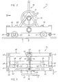
- FIG. 1 shows a rail grinding machine, designated as a whole by 100, which essentially comprises a first base frame 30 designed to hold a first grinding device 10 and a second grinding device 20.
- first base frame 30 designed to hold a first grinding device 10 and a second grinding device 20.
- first base frame 30 viewed in the transport direction X, spaced-apart rollers 31 and 32 are provided, which are arranged on the one rail 2 of a track 1 formed from two rails 2, 2 'arranged parallel to one another.
- Corresponding guide rollers 3 and 4 are also provided on the base frame 30.
- the first grinding device 10 is used to machine the rail surface in the longitudinal direction and the second grinding device 20 is used to process the rail in the transverse direction.
- both grinding devices 10 and 20 are designed to be height-adjustable relative to the rail surface by means of elements (not shown) in arrow direction Z and Z '.
- the first grinding device 10 can also be pivoted about an axis body 11 oriented transversely to the transport direction X of the rail grinding machine 100 in the arrow direction X '.
- the second grinding device 20 is transverse to the longitudinal direction of the rails 2, 2 'by means of a corresponding adjusting device 21 adjustable.
- a single-track device 75 Arranged on the side opposite the first grinding device 10 is a single-track device 75 designed for so-called single-railing of the entire rail grinding machine 100, which is described in detail below.
- FIG. 2 shows the single track device 75 shown in view and one can see a second base frame 45, two spaced-apart rollers 31 'and 32' on the other rail 2 'of the track 1, which correspond to those on the first base frame 30 (FIG. 1) mounted rollers 31 and 32 are arranged.
- a support frame 50 for a spindle device 60 is arranged on the second base frame 45, which is operatively connected to the first base frame 30.
- the second base frame 45 for the single-track operation of the rail grinding machine can be adjusted relative to the first base frame 30, that is to say transversely to the transport or track longitudinal direction.
- the second base frame 45 essentially comprises a first frame part 40 which is operatively connected to the first base frame 30 and a second frame part 46.
- the two frame parts 40 and 46 are over a guide tube 44 is operatively connected to one another such that the second frame part 46 is adjustable relative to the first frame part 40.
- the first frame part 40 has a side member 41 and two side parts 42, 42 'and is firmly connected to the opposite first base frame 30 in a manner not shown.
- the second frame part 46 has two longitudinal beams 46 ′, 46 ′′ arranged at a parallel distance from one another and two side parts 47, 47 ′ arranged thereon.
- the second frame part 46 is essentially supported with the side parts 47 and 47 'on the side parts 42 and 42' of the first frame part 40 and is connected to one another by the guide tube 44 in such a way that, as already mentioned above, the second frame part 46 with the rollers 31 ' , 32 'for the single track operation relative to the first frame part 40, ie, transverse to the longitudinal direction of the track 1 in the arrow direction Y is adjustable.
- the two frame parts 40 and 46 are operatively connected to one another by the guide tube 44 penetrating the frame parts and by two spring elements, preferably by two gas pressure springs 49, 49 '.
- the two gas pressure springs 49, 49 ' are arranged at one end on the side parts 42, 42' of the first frame part 40 and at the other end on the side parts 47, 47 'of the second frame part 46 and fastened accordingly.
- FIG. 4 shows a side view according to arrow direction IV in FIG. 2 of a portion of the single track device 75 with the support frame 50 and the spindle device 60 and one can also see the schematically illustrated base frame 30, the first frame part 40 and the guide tube 44, which has one end 44 ′′ penetrates the side member 41 and with the other end 44 ′ the two side members 46 ′, 46 ′′ (FIG. 3) of the second frame part 46. Furthermore, one can see the gas pressure spring 49 'and the one roller 31'.
- the support frame 50 On the one longitudinal beam 46 '(FIG. 3) of the second frame part 46, the support frame 50, designated in its entirety by 50, for the spindle device 60 is arranged.
- the support frame 50 is arranged and fastened to the second frame part 46 with a first support part 51 designed for mounting the spindle device 60.
- a bearing piece 43 ′ for a threaded spindle 62 of the spindle device 60 is provided on the support part 43.
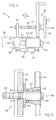
- FIG. 5 shows, in a sectional view and on a larger scale, a section of the spindle device 60 according to FIG. 2 and one recognizes the support part 51 of the support frame 50 provided with a corresponding opening 51 'for the threaded spindle 62. for example fastened by means of a holding piece 64.
- the holding piece 64 is provided with a recess 64 ', in which a flange piece 65' of a spindle nut 65 is arranged.
- the spindle nut 65 is operatively connected via a wedge 63 or the like to a handle 61 'of a handwheel 61 of the spindle device 60.
- the handwheel 61 is rotated accordingly.
- the spindle nut 65 which is operatively connected to the handwheel 61, is moved accordingly on the fixed threaded spindle 62 and, at the same time, the second frame part 46, which is mounted on the guide tube 44, with the support frame 50, as indicated in FIG.
- the presetting is carried out in such a way that the two rollers 31 'and 32' with their guides, which are not described in more detail, are at a short distance from the rail body.
- the frame part 46 with the two rollers 31 ', 32' is counteracted by the restoring force of the gas pressure springs 49,49 'in the direction of the arrow Y', as shown in FIG the rail 2 'pressed.
- the resilient restoring force of the gas pressure springs 49, 49 'it is achieved that the two rollers 31' and 32 'with the frame part 46 in the event of any lane changes or in curves depend on the respective distance between the two Automatically adjusts rails 2,2 '.
- the single-track device 75 described above can be attached to existing rail grinding machines in a simple manner. For this purpose, only the fixed base frame 30 is to be correspondingly coupled to the base frame 45 or slidably mounted on the guide tube 44.
- the counter pressure against the relative movement of the two frame parts 40, 46 is preferably achieved with a gas pressure spring 49, 49 '.
Landscapes
- Engineering & Computer Science (AREA)
- Mechanical Engineering (AREA)
- Architecture (AREA)
- Civil Engineering (AREA)
- Structural Engineering (AREA)
- Finish Polishing, Edge Sharpening, And Grinding By Specific Grinding Devices (AREA)
- Machines For Laying And Maintaining Railways (AREA)
- Machine Tool Units (AREA)
- Polishing Bodies And Polishing Tools (AREA)
Claims (4)
- Machine à meuler les rails qui comprend un premier châssis de base (30) disposé sur un premier rail (2) avec des galets de roulement (31, 32) et destiné à recevoir un dispositif à meuler (10) et un second châssis de base (45) disposé sur un second rail (2') avec des galets de roulement (31', 32') et destiné au logement d'un dispositif d'enraillement (75), au moyen duquel le second châssis de base (45) est mobile transversalement au sens longitudinal des rails par rapport au premier châssis de base (30), le second châssis de base (45) étant disposé sur un tube-guide (44) fixé sur le premier châssis de base (30), caractérisée en ce que le second châssis de base (45) comprend une première partie de châssis (40) avec une partie support (43) pour le logement d'une broche filetée (62) ainsi qu'une seconde partie de châssis (46) avec une partie support (51) pour le logement de la broche filetée (62), au moyen de laquelle la seconde partie de châssis (46) est préréglable transversalement au sens longitudinal des rails par rapport à la première partie de châssis (40) à l'encontre de la pression d'au moins un accumulateur de force (49, 49') de sorte que les deux galets de roulement (31', 32') disposes sur le second châssis de base viennent s'appliquer, en fonctionnement, contre le second rail de roulement (2') de manière élastique sous l'action de la force de rappel de l'accumulateur de force (49, 49').
- Machine à meuler les rails selon la revendication 1, caractérisée en ce que la broche filetée (62) est disposée fixement par une extrémité sur la partie support (43) de la partie de châssis (40) et, avec l'autre extrémité, est reliée, par un écrou à broche (65) relié activement à la partie support associée (51), à un volant (61) de manière à rendre mobile, par rotation du volant (61), la seconde partie de châssis (46).
- Machine à meuler les rails selon la revendication 2, caractérisée en ce que l'écrou à broche (65) relié activement au volant (61) est logé dans une pièce de retenue (64) disposée et fixée dans la partie support (51) fixée à la partie de châssis réglable (46).
- Machine à meuler les rails selon la revendication 1, caractérisée en ce qu'il est prévu, en tant qu'accumulateur de force (49, 49') au moins un ressort à pression de gaz ou de vis (49, 49') qui est disposé et logé par une extrémité sur la première partie de châssis (40) et par l'autre extrémité sur la seconde partie de châssis (46) du second châssis de base (45).
Applications Claiming Priority (2)
| Application Number | Priority Date | Filing Date | Title |
|---|---|---|---|
| CH01037/91A CH688481A5 (de) | 1991-04-08 | 1991-04-08 | Schienen-Schleifmaschine. |
| CH1037/91 | 1991-04-08 |
Publications (2)
| Publication Number | Publication Date |
|---|---|
| EP0512159A1 EP0512159A1 (fr) | 1992-11-11 |
| EP0512159B1 true EP0512159B1 (fr) | 1995-02-15 |
Family
ID=4200986
Family Applications (1)
| Application Number | Title | Priority Date | Filing Date |
|---|---|---|---|
| EP91119922A Expired - Lifetime EP0512159B1 (fr) | 1991-04-08 | 1991-11-22 | Machine à meuler les rails |
Country Status (4)
| Country | Link |
|---|---|
| EP (1) | EP0512159B1 (fr) |
| AT (1) | ATE118570T1 (fr) |
| CH (1) | CH688481A5 (fr) |
| DE (1) | DE59104626D1 (fr) |
Families Citing this family (5)
| Publication number | Priority date | Publication date | Assignee | Title |
|---|---|---|---|---|
| CH690963A5 (fr) * | 1996-12-20 | 2001-03-15 | Speno Internat S A | Dispositif pour la finition du reprofilage en voie et en continu de la surface du champignon d'au moins un rail d'une voie ferrée. |
| CN106223146A (zh) * | 2016-09-07 | 2016-12-14 | 北京交通大学 | 开式砂带钢轨高速打磨车 |
| CN106223145B (zh) * | 2016-09-07 | 2018-10-12 | 北京交通大学 | 整体施压型闭式砂带钢轨打磨车 |
| CN107984349A (zh) * | 2017-11-24 | 2018-05-04 | 中铁五局集团第六工程有限责任公司 | 一种道床板间伸缩缝打磨机 |
| CN110258215A (zh) * | 2019-07-19 | 2019-09-20 | 江苏瑞力泰铁路科技有限公司 | 一种锂电仿形打磨机 |
Citations (1)
| Publication number | Priority date | Publication date | Assignee | Title |
|---|---|---|---|---|
| FR866566A (fr) * | 1940-08-02 | 1941-08-20 | Appareil roulant pour vérification de voies ferrées |
Family Cites Families (3)
| Publication number | Priority date | Publication date | Assignee | Title |
|---|---|---|---|---|
| DE3243602A1 (de) * | 1982-11-25 | 1984-05-30 | Elektro-Thermit Gmbh, 4300 Essen | Auf einer oder beiden schiene(n) eines gleises verfahrbare schienenschleifmaschine |
| CH670667A5 (en) * | 1987-02-09 | 1989-06-30 | Speno International | Rail reshaping equipment for railway track - has chassis supported on wheels at one side and with endless grinding belt other side |
| AT388764B (de) * | 1987-05-12 | 1989-08-25 | Plasser Bahnbaumasch Franz | Band-schleifaggregat zum abschleifen von unregelmaessigkeiten an der schienenkopfflaeche einer oder beider schienen eines verlegten gleises |
-
1991
- 1991-04-08 CH CH01037/91A patent/CH688481A5/de not_active IP Right Cessation
- 1991-11-22 AT AT91119922T patent/ATE118570T1/de not_active IP Right Cessation
- 1991-11-22 DE DE59104626T patent/DE59104626D1/de not_active Expired - Fee Related
- 1991-11-22 EP EP91119922A patent/EP0512159B1/fr not_active Expired - Lifetime
Patent Citations (1)
| Publication number | Priority date | Publication date | Assignee | Title |
|---|---|---|---|---|
| FR866566A (fr) * | 1940-08-02 | 1941-08-20 | Appareil roulant pour vérification de voies ferrées |
Also Published As
| Publication number | Publication date |
|---|---|
| EP0512159A1 (fr) | 1992-11-11 |
| CH688481A5 (de) | 1997-10-15 |
| DE59104626D1 (de) | 1995-03-23 |
| ATE118570T1 (de) | 1995-03-15 |
Similar Documents
| Publication | Publication Date | Title |
|---|---|---|
| EP0139819A2 (fr) | Support pour une perceuse à main | |
| EP0444242A1 (fr) | Machine à meuler les rails | |
| EP3853415B1 (fr) | Dispositif servant à reprofiler et ébarber des rails | |
| DE1652061A1 (de) | Verfahren und Maschine zum Schleifen grossflaechiger Werkstuecke | |
| EP0512159B1 (fr) | Machine à meuler les rails | |
| DE2721244C2 (de) | Maschine zum Schleifen konturierter Werkstücke im Kopierverfahren | |
| DE3016047C2 (fr) | ||
| EP1189726B1 (fr) | Machine-outil | |
| EP0467383A1 (fr) | Dispositif d'affûtage | |
| DE19508864C1 (de) | Maschine zum Ummanteln von länglichen Werkstücken | |
| DE69308287T2 (de) | Vorrichtung zum Beherrschen der Verformung der Führungsstangen eines Trägers für ein Fliessenschneidwerkzeug | |
| DE4007590A1 (de) | Werkstueckspanner | |
| EP0416167B1 (fr) | Dispositif d'affûtage d'une hélice | |
| DE3933863A1 (de) | Schleifmaschine | |
| EP0113389A1 (fr) | Dispositif pour soulager la glissière de guidage pour organes mobiles principalement dans la direction verticale, en particulier organes de machines d'usinage | |
| DE19803375C2 (de) | Vorrichtung zum Positionieren des Werkstücks | |
| EP1211006A1 (fr) | Fraiseuse pour ébavurer les bords de tuyaux ou de barres en acier | |
| DE4108147C1 (en) | Grinding machine for deburring and finishing flat work - has switches operating electronic circuit controlling proportional valve setting pressure in lifting hose | |
| DE3933775C2 (de) | Verstellvorrichtung zur Weiteneinstellung der Greiferschienen einer Transferpresse | |
| WO1988004972A1 (fr) | Dispositif permettant le deplacement rectiligne de pieces ou d'objets | |
| EP0459111B1 (fr) | Suspension ajustable | |
| DE3929001A1 (de) | Einrichtung zur hoehenverstellung mit stetigem gewichtsausgleich | |
| DE19953283A1 (de) | Verstellbare Schlitteneinheit für Stanz-, Biege- und Montageautomaten | |
| EP0761852A1 (fr) | Banc d'étirage avec appareil de reglage de l'écartement des rouleaux d'étirage | |
| DE20120338U1 (de) | Vorrichtung zur Bearbeitung von Schienen |
Legal Events
| Date | Code | Title | Description |
|---|---|---|---|
| PUAI | Public reference made under article 153(3) epc to a published international application that has entered the european phase |
Free format text: ORIGINAL CODE: 0009012 |
|
| AK | Designated contracting states |
Kind code of ref document: A1 Designated state(s): AT BE CH DE DK ES FR GB GR IT LI LU NL SE |
|
| 17P | Request for examination filed |
Effective date: 19921204 |
|
| 17Q | First examination report despatched |
Effective date: 19930503 |
|
| ITF | It: translation for a ep patent filed | ||
| GRAA | (expected) grant |
Free format text: ORIGINAL CODE: 0009210 |
|
| AK | Designated contracting states |
Kind code of ref document: B1 Designated state(s): AT BE CH DE DK ES FR GB GR IT LI LU NL SE |
|
| PG25 | Lapsed in a contracting state [announced via postgrant information from national office to epo] |
Ref country code: GR Free format text: LAPSE BECAUSE OF FAILURE TO SUBMIT A TRANSLATION OF THE DESCRIPTION OR TO PAY THE FEE WITHIN THE PRESCRIBED TIME-LIMIT Effective date: 19950215 Ref country code: ES Free format text: THE PATENT HAS BEEN ANNULLED BY A DECISION OF A NATIONAL AUTHORITY Effective date: 19950215 Ref country code: DK Effective date: 19950215 |
|
| REF | Corresponds to: |
Ref document number: 118570 Country of ref document: AT Date of ref document: 19950315 Kind code of ref document: T |
|
| REF | Corresponds to: |
Ref document number: 59104626 Country of ref document: DE Date of ref document: 19950323 |
|
| ET | Fr: translation filed | ||
| GBT | Gb: translation of ep patent filed (gb section 77(6)(a)/1977) |
Effective date: 19950323 |
|
| PG25 | Lapsed in a contracting state [announced via postgrant information from national office to epo] |
Ref country code: SE Effective date: 19950515 |
|
| PG25 | Lapsed in a contracting state [announced via postgrant information from national office to epo] |
Ref country code: LU Free format text: LAPSE BECAUSE OF NON-PAYMENT OF DUE FEES Effective date: 19951130 |
|
| PLBE | No opposition filed within time limit |
Free format text: ORIGINAL CODE: 0009261 |
|
| STAA | Information on the status of an ep patent application or granted ep patent |
Free format text: STATUS: NO OPPOSITION FILED WITHIN TIME LIMIT |
|
| 26N | No opposition filed | ||
| REG | Reference to a national code |
Ref country code: GB Ref legal event code: IF02 |
|
| PGFP | Annual fee paid to national office [announced via postgrant information from national office to epo] |
Ref country code: DE Payment date: 20041105 Year of fee payment: 14 |
|
| PGFP | Annual fee paid to national office [announced via postgrant information from national office to epo] |
Ref country code: AT Payment date: 20041110 Year of fee payment: 14 |
|
| PGFP | Annual fee paid to national office [announced via postgrant information from national office to epo] |
Ref country code: NL Payment date: 20041111 Year of fee payment: 14 Ref country code: LU Payment date: 20041111 Year of fee payment: 14 |
|
| PGFP | Annual fee paid to national office [announced via postgrant information from national office to epo] |
Ref country code: FR Payment date: 20041112 Year of fee payment: 14 |
|
| PGFP | Annual fee paid to national office [announced via postgrant information from national office to epo] |
Ref country code: GB Payment date: 20041122 Year of fee payment: 14 |
|
| PGFP | Annual fee paid to national office [announced via postgrant information from national office to epo] |
Ref country code: BE Payment date: 20041201 Year of fee payment: 14 |
|
| PGFP | Annual fee paid to national office [announced via postgrant information from national office to epo] |
Ref country code: CH Payment date: 20050223 Year of fee payment: 14 |
|
| PG25 | Lapsed in a contracting state [announced via postgrant information from national office to epo] |
Ref country code: IT Free format text: LAPSE BECAUSE OF NON-PAYMENT OF DUE FEES;WARNING: LAPSES OF ITALIAN PATENTS WITH EFFECTIVE DATE BEFORE 2007 MAY HAVE OCCURRED AT ANY TIME BEFORE 2007. THE CORRECT EFFECTIVE DATE MAY BE DIFFERENT FROM THE ONE RECORDED. Effective date: 20051122 Ref country code: GB Free format text: LAPSE BECAUSE OF NON-PAYMENT OF DUE FEES Effective date: 20051122 Ref country code: AT Free format text: LAPSE BECAUSE OF NON-PAYMENT OF DUE FEES Effective date: 20051122 |
|
| PG25 | Lapsed in a contracting state [announced via postgrant information from national office to epo] |
Ref country code: LI Free format text: LAPSE BECAUSE OF NON-PAYMENT OF DUE FEES Effective date: 20051130 Ref country code: CH Free format text: LAPSE BECAUSE OF NON-PAYMENT OF DUE FEES Effective date: 20051130 Ref country code: BE Free format text: LAPSE BECAUSE OF NON-PAYMENT OF DUE FEES Effective date: 20051130 |
|
| PG25 | Lapsed in a contracting state [announced via postgrant information from national office to epo] |
Ref country code: NL Free format text: LAPSE BECAUSE OF NON-PAYMENT OF DUE FEES Effective date: 20060601 Ref country code: DE Free format text: LAPSE BECAUSE OF NON-PAYMENT OF DUE FEES Effective date: 20060601 |
|
| REG | Reference to a national code |
Ref country code: CH Ref legal event code: PL |
|
| GBPC | Gb: european patent ceased through non-payment of renewal fee |
Effective date: 20051122 |
|
| PG25 | Lapsed in a contracting state [announced via postgrant information from national office to epo] |
Ref country code: FR Free format text: LAPSE BECAUSE OF NON-PAYMENT OF DUE FEES Effective date: 20060731 |
|
| NLV4 | Nl: lapsed or anulled due to non-payment of the annual fee |
Effective date: 20060601 |
|
| REG | Reference to a national code |
Ref country code: FR Ref legal event code: ST Effective date: 20060731 |
|
| BERE | Be: lapsed |
Owner name: *ELAUGEN G.M.B.H. ZURICH SCHWEISS- UND SCHLEIFTECH Effective date: 20051130 |