EP0510046B1 - Procede permettant d'enfermer un substrat - Google Patents
Procede permettant d'enfermer un substrat Download PDFInfo
- Publication number
- EP0510046B1 EP0510046B1 EP91902110A EP91902110A EP0510046B1 EP 0510046 B1 EP0510046 B1 EP 0510046B1 EP 91902110 A EP91902110 A EP 91902110A EP 91902110 A EP91902110 A EP 91902110A EP 0510046 B1 EP0510046 B1 EP 0510046B1
- Authority
- EP
- European Patent Office
- Prior art keywords
- slideway
- sleeve
- substrate
- clip
- legs
- Prior art date
- Legal status (The legal status is an assumption and is not a legal conclusion. Google has not performed a legal analysis and makes no representation as to the accuracy of the status listed.)
- Expired - Lifetime
Links
- 239000000758 substrate Substances 0.000 title claims abstract description 40
- 238000000034 method Methods 0.000 title claims abstract description 17
- 238000004891 communication Methods 0.000 claims description 6
- 239000012530 fluid Substances 0.000 claims description 4
- 239000003566 sealing material Substances 0.000 description 10
- 239000004831 Hot glue Substances 0.000 description 7
- 238000009434 installation Methods 0.000 description 7
- 239000004020 conductor Substances 0.000 description 2
- 230000007613 environmental effect Effects 0.000 description 2
- 239000004952 Polyamide Substances 0.000 description 1
- 239000000853 adhesive Substances 0.000 description 1
- 230000001070 adhesive effect Effects 0.000 description 1
- 230000004888 barrier function Effects 0.000 description 1
- 230000015572 biosynthetic process Effects 0.000 description 1
- 230000000903 blocking effect Effects 0.000 description 1
- 239000011248 coating agent Substances 0.000 description 1
- 238000000576 coating method Methods 0.000 description 1
- 239000002131 composite material Substances 0.000 description 1
- 239000000356 contaminant Substances 0.000 description 1
- 238000013461 design Methods 0.000 description 1
- 239000011521 glass Substances 0.000 description 1
- 238000003780 insertion Methods 0.000 description 1
- 230000037431 insertion Effects 0.000 description 1
- 238000007689 inspection Methods 0.000 description 1
- 239000000463 material Substances 0.000 description 1
- 239000002184 metal Substances 0.000 description 1
- 230000003287 optical effect Effects 0.000 description 1
- 229920002647 polyamide Polymers 0.000 description 1
- 229920000098 polyolefin Polymers 0.000 description 1
- 239000011208 reinforced composite material Substances 0.000 description 1
- 230000000717 retained effect Effects 0.000 description 1
- 238000005096 rolling process Methods 0.000 description 1
- 238000007789 sealing Methods 0.000 description 1
- 238000012360 testing method Methods 0.000 description 1
Images
Classifications
-
- B—PERFORMING OPERATIONS; TRANSPORTING
- B29—WORKING OF PLASTICS; WORKING OF SUBSTANCES IN A PLASTIC STATE IN GENERAL
- B29C—SHAPING OR JOINING OF PLASTICS; SHAPING OF MATERIAL IN A PLASTIC STATE, NOT OTHERWISE PROVIDED FOR; AFTER-TREATMENT OF THE SHAPED PRODUCTS, e.g. REPAIRING
- B29C63/00—Lining or sheathing, i.e. applying preformed layers or sheathings of plastics; Apparatus therefor
- B29C63/38—Lining or sheathing, i.e. applying preformed layers or sheathings of plastics; Apparatus therefor by liberation of internal stresses
- B29C63/42—Lining or sheathing, i.e. applying preformed layers or sheathings of plastics; Apparatus therefor by liberation of internal stresses using tubular layers or sheathings
-
- B—PERFORMING OPERATIONS; TRANSPORTING
- B29—WORKING OF PLASTICS; WORKING OF SUBSTANCES IN A PLASTIC STATE IN GENERAL
- B29C—SHAPING OR JOINING OF PLASTICS; SHAPING OF MATERIAL IN A PLASTIC STATE, NOT OTHERWISE PROVIDED FOR; AFTER-TREATMENT OF THE SHAPED PRODUCTS, e.g. REPAIRING
- B29C61/00—Shaping by liberation of internal stresses; Making preforms having internal stresses; Apparatus therefor
- B29C61/06—Making preforms having internal stresses, e.g. plastic memory
- B29C61/0608—Making preforms having internal stresses, e.g. plastic memory characterised by the configuration or structure of the preforms
- B29C61/0641—Clips for dividing preforms or forming branch-offs
-
- H—ELECTRICITY
- H02—GENERATION; CONVERSION OR DISTRIBUTION OF ELECTRIC POWER
- H02G—INSTALLATION OF ELECTRIC CABLES OR LINES, OR OF COMBINED OPTICAL AND ELECTRIC CABLES OR LINES
- H02G15/00—Cable fittings
- H02G15/08—Cable junctions
- H02G15/18—Cable junctions protected by sleeves, e.g. for communication cable
- H02G15/1806—Heat shrinkable sleeves
-
- Y—GENERAL TAGGING OF NEW TECHNOLOGICAL DEVELOPMENTS; GENERAL TAGGING OF CROSS-SECTIONAL TECHNOLOGIES SPANNING OVER SEVERAL SECTIONS OF THE IPC; TECHNICAL SUBJECTS COVERED BY FORMER USPC CROSS-REFERENCE ART COLLECTIONS [XRACs] AND DIGESTS
- Y10—TECHNICAL SUBJECTS COVERED BY FORMER USPC
- Y10S—TECHNICAL SUBJECTS COVERED BY FORMER USPC CROSS-REFERENCE ART COLLECTIONS [XRACs] AND DIGESTS
- Y10S174/00—Electricity: conductors and insulators
- Y10S174/08—Shrinkable tubes
-
- Y—GENERAL TAGGING OF NEW TECHNOLOGICAL DEVELOPMENTS; GENERAL TAGGING OF CROSS-SECTIONAL TECHNOLOGIES SPANNING OVER SEVERAL SECTIONS OF THE IPC; TECHNICAL SUBJECTS COVERED BY FORMER USPC CROSS-REFERENCE ART COLLECTIONS [XRACs] AND DIGESTS
- Y10—TECHNICAL SUBJECTS COVERED BY FORMER USPC
- Y10S—TECHNICAL SUBJECTS COVERED BY FORMER USPC CROSS-REFERENCE ART COLLECTIONS [XRACs] AND DIGESTS
- Y10S264/00—Plastic and nonmetallic article shaping or treating: processes
- Y10S264/71—Processes of shaping by shrinking
-
- Y—GENERAL TAGGING OF NEW TECHNOLOGICAL DEVELOPMENTS; GENERAL TAGGING OF CROSS-SECTIONAL TECHNOLOGIES SPANNING OVER SEVERAL SECTIONS OF THE IPC; TECHNICAL SUBJECTS COVERED BY FORMER USPC CROSS-REFERENCE ART COLLECTIONS [XRACs] AND DIGESTS
- Y10—TECHNICAL SUBJECTS COVERED BY FORMER USPC
- Y10T—TECHNICAL SUBJECTS COVERED BY FORMER US CLASSIFICATION
- Y10T29/00—Metal working
- Y10T29/49—Method of mechanical manufacture
- Y10T29/49826—Assembling or joining
- Y10T29/49863—Assembling or joining with prestressing of part
- Y10T29/49865—Assembling or joining with prestressing of part by temperature differential [e.g., shrink fit]
Definitions
- the present invention relates to a method of enclosing a substrate, particularly to provide environmental protection, especially by employing a heat-shrinkable sleeve, and preferably where the substrate comprises a cable or a pipe, particularly a telecommunications cable.
- Environmental protection is required around cable splices generally to make good cable jacket that has been removed from the cable ends to expose the internal conductors for electrical (or optical) splicing.
- a cable splice case is built up around the cable splice such that it bridges intact cable jacket at each side of the splice. In this way contaminants such as moisture can be kept away from the otherwise exposed conductor splices.
- Splice cases are now commonly made by installing around the splice a dimensionally-recoverable, usually heat-shrinkable, sleeve.
- a heat-shrinkable sleeve may be supplied over-size, and then heated to cause close, environmentally-sealing, fitting to the underlying cable splice.
- a wrap-around heat-shrinkable sleeve is disclosed in GB 1155470 (Raychem).
- a sleeve may be installed directly over the cable splice or other substrate to be protected, or a liner or other article may first be installed and the sleeve then shrunk around the liner.
- a liner may give mechanical strength to the resulting splice case, may protect the substrate from the heat applied during heat-shrinkage of the sleeve, or may add to the water-vapour barrier properties of the sleeve.
- the liner may serve to render the changes in size smooth thereby facilitating installation of the sleeve.
- the liner may have frusto-conical ends, which may be produced by providing tapering fingers at the ends of a cylinder (giving the appearance of crowns) which are then bent inwards towards the axis of the cylinder.
- the cylinders may, for example, comprise two half-shells or may result from rolling up an initially substantially flat sheet.
- the ability to communicate with the inside of a splice case may be useful, for example to monitor or to change conditions therein.
- some telecommunications cables are pressurized with dry air to protect them, and pressure access points are needed for supply of air or for testing.
- some line such as a pressure access tube must pass through the sleeve, or between the sleeve and the substrate enclosed thereby.
- EP 0244209 discloses provision of a valve in the sleeve. Electrical or other communication may be required for other purposes, and GB 2112224 (Raychem) may be cited as a further example.
- US 4400579 discloses in figures 14A and 14B the use of a trident clip to provide an inlet for pressurized air within a cable splice.
- the central leg incorporating the air inlet is within a heat recoverable sleeve and the two legs are outside the sleeve.
- the clip helps to provide a good seal around the air inlet.
- the clip and air inlet must be slid along the cable over the sleeve after the sleeve has been placed around the cable.
- the present invention provides a method of enclosing a substrate within a heat-shrinkable sleeve, which comprises the steps of:
- the substrate is preferably elongate, and more preferably comprises a pipe or cable such as telecommunications cable. In particular, it comprises a cable splice.
- Step (a) preferably comprises fixing the slideway against movement along the substrate
- step (c) preferably comprises sliding the clip along the slideway.
- a component such as the slideway
- sliding of the clip causes the clip to slide with respect to the slideway which is preferably not displaced by friction of the sliding clip.
- the slideway may comprise first and second parts that move telescopically with respect to one another, the first part being attached to the substrate and the second part being attached to the clip.
- the substrate is elongate, and the slideway is attached to the substrate to allow movement thereof along the substrate, and the clip is fixed to the slideway against movement along the slideway.
- the slideway preferably comprises a tube, preferably a substantially rigid tube, preferably comprising metal, and preferably having means such as a valve that can control passage of fluid therethrough.
- the slideway is elongate and at least when installed provides a fixed third leg of the clip, preferably positioned between and substantially aligned with said two legs, step (c) resulting in a loop of sleeve passing between said two legs and around the slideway.
- the slideway is elongate and at least when installed passes through a bridge portion joining said two legs of the clip such that the slidway is preferably positioned between, is substantially aligned with and is slidable with respect to said two legs, step (c) resulting in a loop of sleeve passing between said two legs and around the slideway.
- the slideway is preferably positioned such that it extends from a position that becomes enclosed by the sleeve to a position that remains outside the sleeve.
- the seal provided by a heat-shrinkable sleeve is often enhanced by the presence of a coating of a hot-melt adhesive or other sealing material on an inner surface of the sleeve, which sealing material may flow on heat-installation of the sleeve to fill any voids that would otherwise remain as leak paths.
- sealing material does not block the end of the slideway to be within the final enclosure, and the slideway is therefore preferably fixed to the cable such that that end remains at the same position.
- the clip is then preferably slid along the slideway to engage the sleeve.
- the sleeve is preferably installed after a liner has been correctly positioned around the cable splice, and a liner having crowned ends (see GB 1431167 referred to above) may be located by taping its crowned ends onto the cables. With the crowned ends thus secured it would in general be impossible to force a pressure access tube past the crowns into the splice case volume within, which is where an end of the tube must be if it is not to become blocked with sealing material. Thus, such a tube should be installed before (or during) installation of the liner, and therefore before installation of the sleeve.
- a clip that is attached to the slideway may serve to form a branch-off between two substrates that is to be sealed by the sleeve.
- said clip serves only to locate the slideway and to help seal around it, preferably by causing or facilitating conformance of the sleeve around it.
- branch-off clips be used that are separate from, and act independently of, the clip plus slideway of the present invention.
- the slideway can be fixed with respect to the cable in any suitable way.
- the slideway comprises an elongate tube
- These collars may then be secured to the cable by for example tapes, bands or hose clamps (such as those known by the Trade Mark Jubilee Clips).
- the collars may have a circumferentially-extending recess for receipt of the band or tape etc.
- the collars may hold the slideway a small distance (for example 1-5mm) from the cable so that the clip, through a hole in which the slideway may pass, is free to move.
- One such collar is preferably positioned at (or inwardly) of the position to which the ends of the crowns of a liner will reach. Then, and if means is provided on the slideway preventing it being slid out of that collar, the end of the slideway will be retained inside the liner and undesired blocking of it by adhesive during installation will be avoided.
- the crown ends meet the collar, and are taped down onto it.
- An end of the slideway that remains outside the sleeve is preferably angled away from the cable for ease of connection to an air supply line or pressure guage. That end may also be provided with a valve such as that known by the Trade Mark, Schrader, and optionally with a valve cap.
- the slideway and/or the clip may be coated, or otherwise used with, a sealing material such as a hot melt adhesive.
- the slideway and/or the clip may serve also as electrical communication to the inside of the sleeve, for example for connection to the shield layer of the cable which will in general be exposed at the end of the cable jacket.
- the legs of the clip may be moveable relative to one another, and/or moveable in orientation relative to that of the slideway. Movement together of the legs and locking in that configuration after the clip has been brought to the sleeve may facilitate installation.
- the sleeve may comprise any suitable material, particularly one based on cross-linked polyolefin and preferably coated with a polyamide or other hot-melt adhesive.
- a preferred sleeve comprises a fibre-reinforced composite material, particularly one that is heat-shrinkable by virtue of heat-shrinkable fibres therein.
- Such a composite material may be reinforced by non-shrinkable fibres, for example glass.
- the sleeve is preferably of wraparound design.
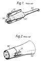
- FIG 1 shows a prior art branch-off clip 51 incorporating a valve as shown in Figure 14b of US 4400579 (Raychem).
- the clip is a trident whose central leg 53 is hollow and is provided with a valve 54 and an inlet duct 55.
- the central leg 53 acts as a substrate in the branch-off technique disclosed in that prior art.
- the way in which that branch-off is made is shown in Figure 2 (figure 14a of US 4400579).
- the clip 51 is simply positioned over the end of a sleeve 52 (shown partially) so as to form two conduits in the sleeve, one of which is occupied by a cable 56 and the other by the central leg 53 of the clip.
- the hollow central leg 53 therefore provides pressure access into the enclosure formed by the sleeve (ie into the right hand part of the sleeve, most of which is omitted from the drawing).
- the sleeve 52 is shown in its shrunk state in which it can be seen tightly to engage the cable 56 and the central leg 53.
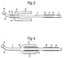
- Figure 3 shows a slideway 1 to which a clip 2 is attached such that the clip can slide along the slideway.
- the clip comprises two legs 3 and a bridge portion 4 which may be of any suitable shape and preferably through which the slideway passes.
- the clip may have a hollow middle leg aligned with the legs 3 and through which the slideway 1 passes. That middle leg may be coated with or may comprise a hot-melt adhesive or other sealing material.
- Collars or other means 5 are provided by means of which the slideway can be fixed or otherwise attached to a cable or other substrate.
- the collars 5 may have circumferentially-extending recesses or holes 6 therein by means of which the collars may be fixed by bands etc to an underlying cable.
- the slideway may have an end cap 7 or other means, for example of interference fit to prevent complete withdrawal of the slideway through the collar 6.
- An end of the slideway that remains exposed may be shaped as at 8 away from an underlying substrate for ease of access to a valve 9 etc that it may carry.
- Figure 4 is similar to figure 3 except that the slideway 1 is intended to slide with respect to a cable on which it is to be mounted.
- the slideway slides within a collar 5, and the clip 3 is fixed with respect to, and may be integral with (at position 10) the slideway 1.
- a portion of the slideway may be coated or otherwise supplied with a hot-melt adhesive or other sealing material 11. If desired, such a sealing material may be supplied separately in this or other embodiments.
- the slideway 1 is in (at least) two telescopic parts 12 and 13 one of which can slide within (or adjacent) the other.
- One or each part may be coated with or comprise a hot-melt adhesive or other sealing material.
- An electrical connection, such as a lead 14, is provided which can allow communication into a splice case which the slideway and clip help to form.
- any of the clips used in the invention may be provided with legs that are fixed or are moveable with respect for example to one another.
- Moveable legs may facilitate positioning of the clip correctly with respect to the sleeve.
- the clip may be slid into position and the legs then correctly positioned with respect to each other and/or with respect to the slideway.
- each leg is pivotally fixed to a bridge portion of the clip such that the distal ends of the legs can swing together to meet the sleeve.
- a locking mechanism may be provided to prevent them opening out again in use.
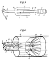
- FIG. 6 Formation of a splice case is shown in figure 6.
- a heat-shrinkable sleeve 15 is positioned around a cable 17, which may be spliced to one or more other cables within the sleeve, to the right-hand side of the part of the sleeve illustrated.
- a liner 16 surrounds the cable and splice within the sleeve 15, and a crowned end 18 of the liner has tapered fingers thereof bent inwards towards the axis of the liner and down onto the cable. The fingers may be taped in that configuration to locate the liner with respect to the cable.
- the collars 5 are secured to the cable 17 by bands 19 that pass around the cable and around or through the collars 5.
- the crowns 18 are preferably aligned with and optionally taped down onto one of the collars 5 and corresponding band 19.
- the clip 2 is slid in the direction of the arrows over an end of the sleeve, thus deforming the sleeve around the slideway.
- the sleeve is then shrunk to produce a sealed outlet thereof analagous to that shown in figure 2.
- the sleeve may be internally coated with a hot-melt adhesive or other sealing material to improve the seal between it and the underlying cable.
- the invention provides articles, methods and kits for enclosing a substrate or providing pressure access or other communication. Any one or more of the clips, slideways, fastening devices, sleeves or liners may be selected.
Landscapes
- Engineering & Computer Science (AREA)
- Manufacturing & Machinery (AREA)
- Crystals, And After-Treatments Of Crystals (AREA)
- Packages (AREA)
- Cable Accessories (AREA)
- Container Filling Or Packaging Operations (AREA)
- Insulating Bodies (AREA)
- Clamps And Clips (AREA)
- Supports For Pipes And Cables (AREA)
- Mechanical Treatment Of Semiconductor (AREA)
- Wrappers (AREA)
- Gasket Seals (AREA)
Claims (12)
- Procédé pour enfermer un substrat (17) à l'intérieur d'un manchon thermo-rétractable (15), qui comprend les étapes consistant à :(a) attacher une glissière (1) au substrat (17) ;(b) positionner un manchon rétractable (15) autour du substrat (17) ;(c) faire glisser une attache (2, 3), qui comporte au moins deux branches et qui est attachée à la glissière (1), au moyen de la glissière et par rapport au substrat (17) de façon qu'au moins une partie du manchon (15) vienne se placer entre les branches de l'attache (2, 3) ; et(d) provoquer un retrait thermique du manchon (15).
- Procédé selon la revendication 1, dans lequel le substrat (17) comprend un substrat allongé, l'étape (a) comprend la fixation de la glissière (1) afin qu'elle ne se déplace pas le long du substrat, et l'étape (c) comprend le glissement de l'attache (2, 3) le long de la glissière.
- Procédé selon la revendication 1, dans lequel la glissière (1) comporte des première et seconde parties qui peuvent se déplacer télescopiquement l'une par rapport à l'autre, la première partie (13) étant fixée au substrat (17) et la seconde partie (12) étant fixée à l'attache (2, 3).
- Procédé selon la revendication 1, dans lequel le substrat (17) comprend un substrat allongé et la glissière (1) est attachée au substrat afin qu'elle puisse se déplacer le long du substrat, et l'attache (2, 3) est fixée à la glissière de façon à ne pas se déplacer le long de la glissière.
- Procédé selon l'une quelconque des revendications précédentes, dans lequel la glissière (1) comprend un tube.
- Procédé selon la revendication 5, dans lequel un moyen (9) est prévu, lequel peut commander le passage d'un fluide dans le tube.
- Procedé selon l'une quelconque des revendications precédentes, dans lequel la glissière (1) est allongée et forme une troisième branche fixe de l'attache (2, 3) positionnée entre lesdites deux branches et sensiblement alignées avec elles, l'étape (c) donnant au manchon (15) la forme d'une boucle passant par lesdites deux branches et autour de la glissière.
- Procédé selon l'une quelconque des revendications 1 - 3, dans lequel la glissière (1) est allongée et passe par une partie de pontage joignant lesdites deux branches de l'attache (2, 3) afin que la glissière (1) soit positionnée entre elles, soit sensiblement alignée avec lesdites deux branches et puisse glisser par rapport à elles, l'étape (c) donnant au manchon (15) la forme d'une boucle passant entre lesdites deux branches et autour de la glissière.
- Procédé selon l'une quelconque des revendications précédentes, dans lequel la glissière (1) est positionnée de façon à s'étendre d'une position que le manchon (15) finit par enfermer jusqu'à une position qui reste à l'extérieur du manchon, établissant ainsi une communication entre l'intérieur et l'extérieur d'une enceinte formée par le retrait du manchon autour du substrat (17).
- Dispositif pouvant être utilisé dans un procédé selon l'une quelconque des revendications précédentes, qui comporte ladite glissière (1) et ladite attache (2, 3).
- Dispositif selon la revendication 10, dans lequel ladite glissière (1) comprend un tube ayant un moyen (9) pouvant commander le passage d'un fluide dans ce tube.
- Lot de pièces qui comporte un manchon thermorétractable (15) et un dispositif selon la revendication 10 ou 11.
Applications Claiming Priority (3)
| Application Number | Priority Date | Filing Date | Title |
|---|---|---|---|
| GB909000679A GB9000679D0 (en) | 1990-01-12 | 1990-01-12 | A method of enclosing a substrate |
| GB9000679 | 1990-01-12 | ||
| PCT/GB1991/000036 WO1991010355A2 (fr) | 1990-01-12 | 1991-01-11 | Procede permettant d'enfermer un substrat |
Publications (2)
| Publication Number | Publication Date |
|---|---|
| EP0510046A1 EP0510046A1 (fr) | 1992-10-28 |
| EP0510046B1 true EP0510046B1 (fr) | 1995-12-13 |
Family
ID=10669166
Family Applications (1)
| Application Number | Title | Priority Date | Filing Date |
|---|---|---|---|
| EP91902110A Expired - Lifetime EP0510046B1 (fr) | 1990-01-12 | 1991-01-11 | Procede permettant d'enfermer un substrat |
Country Status (14)
| Country | Link |
|---|---|
| US (1) | US5317797A (fr) |
| EP (1) | EP0510046B1 (fr) |
| JP (1) | JPH05503892A (fr) |
| KR (1) | KR920702904A (fr) |
| CN (1) | CN1053515A (fr) |
| AT (1) | ATE131347T1 (fr) |
| AU (1) | AU635385B2 (fr) |
| BR (1) | BR9105934A (fr) |
| CA (1) | CA2072075A1 (fr) |
| DE (1) | DE69115467T2 (fr) |
| GB (1) | GB9000679D0 (fr) |
| MY (1) | MY106368A (fr) |
| NZ (1) | NZ236746A (fr) |
| WO (1) | WO1991010355A2 (fr) |
Families Citing this family (1)
| Publication number | Priority date | Publication date | Assignee | Title |
|---|---|---|---|---|
| EP0601464B1 (fr) * | 1992-12-08 | 1997-02-26 | RXS Kabelgarnituren Gesellschaft mit beschränkter Haftung | Procédé de réalisation d'une fermeture étanche aux extrémités d'un manchon de câble rétractable et élément d'étanchéité pour celui-ci |
Family Cites Families (3)
| Publication number | Priority date | Publication date | Assignee | Title |
|---|---|---|---|---|
| GB1604981A (en) * | 1978-01-09 | 1981-12-16 | Raychem Sa Nv | Branchoff method |
| US4400579A (en) * | 1978-01-09 | 1983-08-23 | N.V. Raychem S.A. | Branch-off assembly |
| DE3430088A1 (de) * | 1984-08-16 | 1986-02-27 | Philips Patentverwaltung Gmbh, 2000 Hamburg | Klammer zum einziehen einer schrumpfmuffe bei kabelverzweigungen |
-
1990
- 1990-01-12 GB GB909000679A patent/GB9000679D0/en active Pending
-
1991
- 1991-01-11 KR KR1019920701643A patent/KR920702904A/ko not_active Application Discontinuation
- 1991-01-11 EP EP91902110A patent/EP0510046B1/fr not_active Expired - Lifetime
- 1991-01-11 MY MYPI91000045A patent/MY106368A/en unknown
- 1991-01-11 DE DE69115467T patent/DE69115467T2/de not_active Expired - Fee Related
- 1991-01-11 WO PCT/GB1991/000036 patent/WO1991010355A2/fr active IP Right Grant
- 1991-01-11 AU AU70719/91A patent/AU635385B2/en not_active Ceased
- 1991-01-11 JP JP3502476A patent/JPH05503892A/ja active Pending
- 1991-01-11 AT AT91902110T patent/ATE131347T1/de not_active IP Right Cessation
- 1991-01-11 CA CA002072075A patent/CA2072075A1/fr not_active Abandoned
- 1991-01-11 NZ NZ236746A patent/NZ236746A/en unknown
- 1991-01-11 BR BR919105934A patent/BR9105934A/pt not_active Application Discontinuation
- 1991-01-12 CN CN91100318A patent/CN1053515A/zh active Pending
- 1991-01-12 US US07/910,091 patent/US5317797A/en not_active Expired - Fee Related
Also Published As
| Publication number | Publication date |
|---|---|
| CN1053515A (zh) | 1991-07-31 |
| EP0510046A1 (fr) | 1992-10-28 |
| KR920702904A (ko) | 1992-12-17 |
| GB9000679D0 (en) | 1990-03-14 |
| WO1991010355A2 (fr) | 1991-07-25 |
| BR9105934A (pt) | 1992-11-24 |
| US5317797A (en) | 1994-06-07 |
| ATE131347T1 (de) | 1995-12-15 |
| CA2072075A1 (fr) | 1991-07-13 |
| DE69115467D1 (de) | 1996-01-25 |
| NZ236746A (en) | 1993-08-26 |
| MY106368A (en) | 1995-05-30 |
| DE69115467T2 (de) | 1996-08-01 |
| JPH05503892A (ja) | 1993-06-24 |
| AU7071991A (en) | 1991-08-05 |
| WO1991010355A3 (fr) | 1992-01-09 |
| AU635385B2 (en) | 1993-03-18 |
Similar Documents
| Publication | Publication Date | Title |
|---|---|---|
| US4761052A (en) | Optical fibre splice case | |
| US5066095A (en) | Jointing box for optical fiber cables | |
| US4409426A (en) | Splice case | |
| JPS5981130A (ja) | 寸法的熱回復性物品 | |
| CA1214526A (fr) | Article thermoretrecissable | |
| US5300732A (en) | Environmental seal | |
| NZ237136A (en) | Drawing head for optical ribbon cable with end connectors. | |
| US5792991A (en) | Environmental seal | |
| EP0238325A2 (fr) | Indicateur pour manchons à reprise dimensionnelle | |
| EP0510046B1 (fr) | Procede permettant d'enfermer un substrat | |
| WO1991010355A1 (fr) | Procede permettant d'enfermer un substrat | |
| US4767652A (en) | Pressure retaining enclosure | |
| EP0267028A2 (fr) | Ensemble de fermeture | |
| GB2135139A (en) | Heat recoverable article | |
| EP0384053B1 (fr) | Dispositif d'atténuation de contraintes axiales | |
| US5278355A (en) | Environmental sealing | |
| US7257305B1 (en) | Method and apparatus for removing an isolation closure from a fiber optic cable | |
| US4614557A (en) | Pressure retaining enclosure | |
| US4759811A (en) | Method for repair or accessing pressurized cable | |
| WO1991014306A1 (fr) | Fermeture hermetique | |
| KR0171592B1 (ko) | 주위 밀봉 방법 및 그 제품 | |
| GB2221356A (en) | Protecting cable splice | |
| WO1992012843A1 (fr) | Joint d'etancheite pour dispositif en derivation | |
| WO1995015602A1 (fr) | Dispositif d'etancheite au milieu ambiant | |
| EP0057615A2 (fr) | Moyen composite pour prise d'air |
Legal Events
| Date | Code | Title | Description |
|---|---|---|---|
| PUAI | Public reference made under article 153(3) epc to a published international application that has entered the european phase |
Free format text: ORIGINAL CODE: 0009012 |
|
| 17P | Request for examination filed |
Effective date: 19920703 |
|
| AK | Designated contracting states |
Kind code of ref document: A1 Designated state(s): AT BE CH DE DK ES FR GB GR IT LI NL SE |
|
| 17Q | First examination report despatched |
Effective date: 19931021 |
|
| GRAA | (expected) grant |
Free format text: ORIGINAL CODE: 0009210 |
|
| AK | Designated contracting states |
Kind code of ref document: B1 Designated state(s): AT BE CH DE DK ES FR GB GR IT LI NL SE |
|
| PG25 | Lapsed in a contracting state [announced via postgrant information from national office to epo] |
Ref country code: NL Free format text: LAPSE BECAUSE OF FAILURE TO SUBMIT A TRANSLATION OF THE DESCRIPTION OR TO PAY THE FEE WITHIN THE PRESCRIBED TIME-LIMIT Effective date: 19951213 Ref country code: LI Free format text: LAPSE BECAUSE OF FAILURE TO SUBMIT A TRANSLATION OF THE DESCRIPTION OR TO PAY THE FEE WITHIN THE PRESCRIBED TIME-LIMIT Effective date: 19951213 Ref country code: GR Free format text: LAPSE BECAUSE OF FAILURE TO SUBMIT A TRANSLATION OF THE DESCRIPTION OR TO PAY THE FEE WITHIN THE PRESCRIBED TIME-LIMIT Effective date: 19951213 Ref country code: FR Effective date: 19951213 Ref country code: ES Free format text: THE PATENT HAS BEEN ANNULLED BY A DECISION OF A NATIONAL AUTHORITY Effective date: 19951213 Ref country code: DK Effective date: 19951213 Ref country code: CH Free format text: LAPSE BECAUSE OF FAILURE TO SUBMIT A TRANSLATION OF THE DESCRIPTION OR TO PAY THE FEE WITHIN THE PRESCRIBED TIME-LIMIT Effective date: 19951213 Ref country code: BE Effective date: 19951213 Ref country code: AT Effective date: 19951213 |
|
| REF | Corresponds to: |
Ref document number: 131347 Country of ref document: AT Date of ref document: 19951215 Kind code of ref document: T |
|
| REF | Corresponds to: |
Ref document number: 69115467 Country of ref document: DE Date of ref document: 19960125 |
|
| ITF | It: translation for a ep patent filed | ||
| PG25 | Lapsed in a contracting state [announced via postgrant information from national office to epo] |
Ref country code: SE Effective date: 19960313 |
|
| EN | Fr: translation not filed | ||
| NLV1 | Nl: lapsed or annulled due to failure to fulfill the requirements of art. 29p and 29m of the patents act | ||
| REG | Reference to a national code |
Ref country code: CH Ref legal event code: PL |
|
| PLBE | No opposition filed within time limit |
Free format text: ORIGINAL CODE: 0009261 |
|
| STAA | Information on the status of an ep patent application or granted ep patent |
Free format text: STATUS: NO OPPOSITION FILED WITHIN TIME LIMIT |
|
| 26N | No opposition filed | ||
| PGFP | Annual fee paid to national office [announced via postgrant information from national office to epo] |
Ref country code: GB Payment date: 19980102 Year of fee payment: 8 |
|
| PGFP | Annual fee paid to national office [announced via postgrant information from national office to epo] |
Ref country code: DE Payment date: 19980116 Year of fee payment: 8 |
|
| PG25 | Lapsed in a contracting state [announced via postgrant information from national office to epo] |
Ref country code: GB Free format text: LAPSE BECAUSE OF NON-PAYMENT OF DUE FEES Effective date: 19990111 |
|
| GBPC | Gb: european patent ceased through non-payment of renewal fee |
Effective date: 19990111 |
|
| PG25 | Lapsed in a contracting state [announced via postgrant information from national office to epo] |
Ref country code: DE Free format text: LAPSE BECAUSE OF NON-PAYMENT OF DUE FEES Effective date: 19991103 |
|
| PG25 | Lapsed in a contracting state [announced via postgrant information from national office to epo] |
Ref country code: IT Free format text: LAPSE BECAUSE OF NON-PAYMENT OF DUE FEES;WARNING: LAPSES OF ITALIAN PATENTS WITH EFFECTIVE DATE BEFORE 2007 MAY HAVE OCCURRED AT ANY TIME BEFORE 2007. THE CORRECT EFFECTIVE DATE MAY BE DIFFERENT FROM THE ONE RECORDED. Effective date: 20050111 |