EP0509296A1 - Endoskopischer Ultraschallkopf mit Kabelaufrollmechanismus - Google Patents
Endoskopischer Ultraschallkopf mit Kabelaufrollmechanismus Download PDFInfo
- Publication number
- EP0509296A1 EP0509296A1 EP92105355A EP92105355A EP0509296A1 EP 0509296 A1 EP0509296 A1 EP 0509296A1 EP 92105355 A EP92105355 A EP 92105355A EP 92105355 A EP92105355 A EP 92105355A EP 0509296 A1 EP0509296 A1 EP 0509296A1
- Authority
- EP
- European Patent Office
- Prior art keywords
- volume
- cable
- array
- flexible cable
- probe
- Prior art date
- Legal status (The legal status is an assumption and is not a legal conclusion. Google has not performed a legal analysis and makes no representation as to the accuracy of the status listed.)
- Granted
Links
- 239000000523 sample Substances 0.000 title claims abstract description 39
- 238000009558 endoscopic ultrasound Methods 0.000 title claims description 6
- 238000012285 ultrasound imaging Methods 0.000 claims abstract description 7
- 238000002604 ultrasonography Methods 0.000 claims description 18
- 238000013175 transesophageal echocardiography Methods 0.000 claims description 2
- 238000013016 damping Methods 0.000 description 7
- 239000000463 material Substances 0.000 description 7
- 210000003238 esophagus Anatomy 0.000 description 5
- 239000004020 conductor Substances 0.000 description 3
- 238000003384 imaging method Methods 0.000 description 2
- 238000003780 insertion Methods 0.000 description 2
- 230000037431 insertion Effects 0.000 description 2
- 230000002411 adverse Effects 0.000 description 1
- 230000005540 biological transmission Effects 0.000 description 1
- 230000000747 cardiac effect Effects 0.000 description 1
- 150000001875 compounds Chemical class 0.000 description 1
- 238000002592 echocardiography Methods 0.000 description 1
- 230000000694 effects Effects 0.000 description 1
- 230000005284 excitation Effects 0.000 description 1
- 239000004519 grease Substances 0.000 description 1
- 238000000034 method Methods 0.000 description 1
- 230000035945 sensitivity Effects 0.000 description 1
- 239000000126 substance Substances 0.000 description 1
- 230000002861 ventricular Effects 0.000 description 1
Images

Classifications
-
- A—HUMAN NECESSITIES
- A61—MEDICAL OR VETERINARY SCIENCE; HYGIENE
- A61B—DIAGNOSIS; SURGERY; IDENTIFICATION
- A61B8/00—Diagnosis using ultrasonic, sonic or infrasonic waves
- A61B8/12—Diagnosis using ultrasonic, sonic or infrasonic waves in body cavities or body tracts, e.g. by using catheters
-
- A—HUMAN NECESSITIES
- A61—MEDICAL OR VETERINARY SCIENCE; HYGIENE
- A61B—DIAGNOSIS; SURGERY; IDENTIFICATION
- A61B8/00—Diagnosis using ultrasonic, sonic or infrasonic waves
- A61B8/44—Constructional features of the ultrasonic, sonic or infrasonic diagnostic device
- A61B8/4444—Constructional features of the ultrasonic, sonic or infrasonic diagnostic device related to the probe
- A61B8/445—Details of catheter construction
-
- A—HUMAN NECESSITIES
- A61—MEDICAL OR VETERINARY SCIENCE; HYGIENE
- A61B—DIAGNOSIS; SURGERY; IDENTIFICATION
- A61B8/00—Diagnosis using ultrasonic, sonic or infrasonic waves
- A61B8/44—Constructional features of the ultrasonic, sonic or infrasonic diagnostic device
- A61B8/4444—Constructional features of the ultrasonic, sonic or infrasonic diagnostic device related to the probe
- A61B8/4461—Features of the scanning mechanism, e.g. for moving the transducer within the housing of the probe
-
- H—ELECTRICITY
- H01—ELECTRIC ELEMENTS
- H01R—ELECTRICALLY-CONDUCTIVE CONNECTIONS; STRUCTURAL ASSOCIATIONS OF A PLURALITY OF MUTUALLY-INSULATED ELECTRICAL CONNECTING ELEMENTS; COUPLING DEVICES; CURRENT COLLECTORS
- H01R13/00—Details of coupling devices of the kinds covered by groups H01R12/70 or H01R24/00 - H01R33/00
- H01R13/46—Bases; Cases
- H01R13/52—Dustproof, splashproof, drip-proof, waterproof, or flameproof cases
- H01R13/5224—Dustproof, splashproof, drip-proof, waterproof, or flameproof cases for medical use
-
- H—ELECTRICITY
- H02—GENERATION; CONVERSION OR DISTRIBUTION OF ELECTRIC POWER
- H02G—INSTALLATION OF ELECTRIC CABLES OR LINES, OR OF COMBINED OPTICAL AND ELECTRIC CABLES OR LINES
- H02G11/00—Arrangements of electric cables or lines between relatively-movable parts
- H02G11/02—Arrangements of electric cables or lines between relatively-movable parts using take-up reel or drum
Definitions
- Transesophageal echo cardiography is an established technique in the area of cardiac imaging and involves the insertion of an ultrasound probe into a subject's esophagus to scan the heart from inside the esophagus.
- An ultrasound probe may be formed by modifying an endoscope, whereby an ultrasound transducer array is affixed to the distal end of the endoscope.
- the probe is used with an ultrasound imaging system having electronics for remote excitation of the array to obtain cross-sectional images of the heart along a variety of scan planes is well known.
- an ultrasound probe having a rotatable array is suggested for obtaining an improved assessment of left ventricular morphology.
- Another ultrasound probe having a rotatable array is described in U.S. Patent No. 4,543,960 to Harui.
- an ultrasound scanhead has an array mounted on a rotatable base which is driven by a pulley. To rotate the array, control cables attached to the pulley are pulled, causing the pulley to rotate the base on which the array is mounted.
- the transducer elements are electrically connected a flexible cable which provides signals to a standard scan converter. To support rotation, the flexible cable is looped around the base to form a spiral cable assembly in a volume directly below the array.
- the volume requires a somewhat large diameter to accomodate the excess flexible cable in the spiral form. Since the cable is wrapped around the large diameter base, it has a large minimum diameter. The thickness of the cable, multiplied by the number of revolutions required to support rotation also contributes to the large diameter of the volume. Yet another factor is the space between adjacent revolutions of the spiral cable required to allow the spiral to become slack for certain rotational configurations.
- the probe due to the large required diameter of the volume housing the array, the probe has a substantial transverse cross-sectional area which may lead to problems introducing the device into a subject's esophagus. Alternatively, the array size must be reduced which will adversely affect the resolution of the image.
- the present invention avoids the problems of the aforementioned prior art through a unique cable take-up mechanism employed in an endoscopic ultrasound probe.
- the cable take-up mechanism is configured to minimize the diameter of the volume housing the array.
- the distal end of the probe has a smaller cross-sectional area and is easier to introduce into a subject's esophagus.
- the probe comprises a probe housing having a first volume and a second volume.
- a rotatable ultrasound transducer assembly is positioned in the first volume, and a take-up mechanism for a flexible cable, which cable is connected to the transducer assembly in the first volume and is disposed in the second volume, is located in the second volume.
- the take-up mechanism produces changes in the amount of the flexible cable disposed within the second volume corresponding to changes in the amount of flexible cable within the first volume.
- the take-up mechanism allows the array to rotate freely, while ensuring that excess flexible cable is contained in the second volume.
- the first volume of the probe has a smaller diameter than the prior art, resulting in a smaller probe.
- the present invention comprises a probe housing having an inner volume in its distal end and a rear volume adjacent to the inner volume.
- An ultrasound transducer array is supported on a rotatable structure within the inner volume.
- the array is formed of a plurality of transducer elements arranged in a plane and has a scan plane which is perpendicular to the elements of the array.
- a cable take-up mechanism comprises a flexible cable assembly which electrically connects the array to remote ultrasound imaging system electronics.
- the flexible cable assembly comprises a plurality of integrally coupled flex cables, each having a plurality of signal lines printed thereon.
- One end of the flexible cable assembly is attached to the array and the other end is connected to a plurality of conductors which are linked to the remote electronics.
- a first portion of the flexible cable assembly extends from the array and may be fixed in a mass of acoustical damping material contained in the support structure.
- the first portion of the flexible cable assembly extends out of the support structure and forms a loop portion which wraps around the support structure within the inner volume.
- the loop portion extends into the rear volume which is adjacent to the inner volume.
- the flex cable assembly forms a spiral portion.
- the spiral portion has a sufficient number of revolutions of excess cable to support the rotation of the array.
- the innermost section of the spiral portion is preferrably secured within the clamp and is linked to the remote electronics.
- the cable take-up mechanism of this embodiment is configured to minimize the diameter of the inner volume. More specifically, the take-up mechanism is configured such that the spiral portion of the flex cable in the rear volume responds to changes in the loop portion within the inner volume. As the array rotates, the amount of cable forming the loop portion changes, producing corresponding changes in the amount of cable forming the spiral portion as well as the outer diameter of the spiral portion. Thus, the thickness of the loop portion of the flex cable assembly and the space required between revolutions to support rotation have a minimal effect on the diameter or the inner volume.
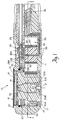
- FIG. 1 is a longitudinal cross-sectional view of a portion of an ultrasound probe in accordance with the present invention.
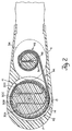
- FIG. 2 is a partial longitudinal cross-sectional view of the probe of FIG. 1 taken along the line 2-2 or FIG. 1.
- FIG. 3 is a partial longitudinal cross-sectional view of the probe according to FIG. 2 with the flexible cable assembly rotated 180°.
- FIG. 1 A longitudinal cross-sectional view of an ultrasound probe illustrating the principles of the present invention is shown in FIG. 1.
- a probe 10 is formed by modifying an endoscope whereby a rotatable ultrasound transducer array 12 is positioned in its distal end.
- the probe 10 provides image data to remote electronics of an ultrasound imaging system which produces two-dimensional cross-sectional images of a subject.
- the probe 10 has a probe housing 11 shaped for insertion into a subject's esophagus.
- the rotatable ultrasound transducer array 12 comprises a plurality of elongated piezoelectric transducer elements arranged in a plane.
- the array is positioned on a support structure 17 within an inner volume 14 located at the distal end of the probe.
- the transducer elements have different mechanical lengths such that the surface of the array 12 has a circular shape to provide maximum sensitivity.
- a compound lens assembly 16 covering the rotatable array 12 serves to focus the energy emitted by the array along a plane which is parallel to the array elements. Additionally, this energy emitted from the array is electronically focused in a plane perpendicular to the plane of the array elements.
- a stationary cover assembly 18 is mounted over the inner housing 11 above the array. The cover prevents undesireable substances from touching the lens.
- a layer of grease 20, located between the lens assembly 16 and the cover 18, serves as a transmission medium.
- the array is electrically connected to a flexible cable assembly 30 for communications with the remote ultrasound imaging electronics. More specifically, the flexible cable assembly extends from the array, through the inner volume 14 and a rear volume 34, to a plurality of individual conductors 39 adjacent to the rear volume which are coupled to the remote ultrasound electronics.
- the flexible cable assembly is a single flex cable comprising a plurality of individual flex cable extensions 30A-D, each having a plurality of signal lines printed thereon.
- these individual flex cables are joined in pairs within the support structure, forming two unitary flex cables.
- flex cables 30A and 30B are integrally coupled as are flex cables 30C and 30D.
- a common end of each flex cable pair is attached to the underside of the array at 32 forming a single flex cable.
- the individual flex cables of the pairs extend in opposite directions, but flex cables 30A and 30D loop back becoming parallel to 30B and 30C within the support structure 17.
- a mass of acoustical damping material 15 fills the volume within support structure 17, encapsulating that portion of the individual flex cables.
- the acoustical damping material 15 absorbs acoustic signals from the back of the array.
- the array 16 may be rotated about an axis extending through the center of the array and a shaft 21 for obtaining cross-sectional images along a variety of scan planes.
- the array is coupled to the rotatable support structure which is mechanically linked to a plurality of ball bearings 22 and to a bearing 23 at the shaft. Rotation of the array is achieved by a rotating cable 24 and a worm gear 26. More specifically, the rotating cable 24, resembling a speedometer cable, is mechanically linked to the worm gear 26. The rotation of the cable 24 causes the worm gear 26 to rotate about a common shaft.
- the worm gear is mechanically linked to a first gear 28A such that rotation of the worm gear causes the first gear to rotate about an axis which is parallel to the axis of rotation for the array.
- the first gear 28A is one of a plurality of gears 28 which are mechanically linked to each other and have parallel axes of rotation.
- the rotation of the worm gear drives the first gear 28A
- the rotation of first gear drives the second gear 28B
- the rotation of the second gear drives the third gear 28C.
- the third gear is mechanically linked to a ring gear 29 which is coupled to the support structure 17.
- the rotation of the third gear causes the ring gear to turn such that the array rotates.
- the take-up mechanism comprising the flex cable assembly 30 in accordance with the present invention is shown in FIG. 2.
- the flex cable assembly has a first portion embedded within the mass of acoustical damping material 15.
- the flex cable assembly protrudes out of the damping material through an opening in the support structure at 41 and extends around the support structure within the inner volume in the form of a loop 42.
- the loop portion 42 becomes straight at 44 and extends into the rear volume 34.
- the flex cable assembly is formed into a spiral portion 46 which is wrapped around a stationary attachment means 36 within the rear volume 34.
- the attachment means preferably comprises a clamp, though any functionally similarly device may be employed.
- the spiral portion has a sufficient number of revolutions of excess cable to support rotation of the array.
- An innermost section 48 of the spiral portion is fixed within the clamp. Also, the innermost section 48 is coupled to the individual conductors 39 (FIG. 1) which are electrically linked to the remote imaging electronics.
- the rotating support structure causes the damping material along with the embedded portion of the flex cable assembly to rotate with it.
- This rotation causes the loop portion 42 to rotate, thereby changing the amount of cable forming the loop portion 42 which surrounds the damping material 15.
- Such changes cause corresponding changes in the amount of cable forming the spiral portion as well as changes in the diameter of the spiral portion.
- clockwise rotation of the array increases the amount of cable forming the loop portion.
- an increase in the amount of cable forming the loop portion causes a decrease in the amount of cable forming the spiral portion and in the diameter of the spiral portion.
- An example of counterclockwise rotation of the array is shown in FIG. 3. In this situation, the rotation of the array has significantly reduced the amount of cable form the loop portion. As such, the amount of cable forming the spiral portion and the outer diameter of the spiral portion have increased.
- the take-up mechanism of this invention comprising flex cable assembly is configured to minimize the required diameter of the inner volume 14.
- the probe has a smaller transverse cross-sectional area and is easier to swallow.
- the present invention has the loop portion 42 within the inner volume 14 driving a spiral portion 46 located in a rear volume 34. The rotation of the array causes the loop portion to form, at most, one complete revolution within the inner housing, and that single revolution is wrapped somewhat tightly against the support structure. Accordingly, the thickness of the loop portion of the flex cable assembly within the inner volume is minimized.
- the spiral portion rotates in response to the loop portion and has a sufficient amount of cable to support rotation of the array.
- the spiral portion 46 is positioned in the rear volume 34 and actually has a smaller transverse cross-sectional diameter than the loop portion. Referring to FIG. 3, this smaller diameter is achieved based on two reasons explained herein.
- the spiral portion is wrapped around the clamp 36 such that the inner diameter of the spiral is smaller than the loop diameter.
- the spiral portion can "take-up" multiple revolutions of cable from the loop portion and still maintain a smaller outer diameter (i.e. transverse cross-sectional outer diameter) than the loop portion.
- the elongated shape of the rear volume 34 has a sufficient volume to accomodate multiple revolutions of the spiral portion even when it becomes slack.
- the take-up mechanism may comprise other forms of the flexible cable such as an "S" shaped cable configuration.
- the probe may comprise a mechanical scanner without departing from the scope of the present invention.
Landscapes
- Life Sciences & Earth Sciences (AREA)
- Health & Medical Sciences (AREA)
- Biomedical Technology (AREA)
- Biophysics (AREA)
- Nuclear Medicine, Radiotherapy & Molecular Imaging (AREA)
- Pathology (AREA)
- Radiology & Medical Imaging (AREA)
- Engineering & Computer Science (AREA)
- Physics & Mathematics (AREA)
- Heart & Thoracic Surgery (AREA)
- Medical Informatics (AREA)
- Molecular Biology (AREA)
- Surgery (AREA)
- Animal Behavior & Ethology (AREA)
- General Health & Medical Sciences (AREA)
- Public Health (AREA)
- Veterinary Medicine (AREA)
- Ultra Sonic Daignosis Equipment (AREA)
Applications Claiming Priority (4)
| Application Number | Priority Date | Filing Date | Title |
|---|---|---|---|
| US07/686,103 US5176142A (en) | 1991-04-16 | 1991-04-16 | Endoscopic ultrasound probe with take-up cable mechanism |
| US686103 | 1991-04-16 | ||
| US68691991A | 1991-04-17 | 1991-04-17 | |
| US686919 | 1991-04-17 |
Publications (2)
| Publication Number | Publication Date |
|---|---|
| EP0509296A1 true EP0509296A1 (de) | 1992-10-21 |
| EP0509296B1 EP0509296B1 (de) | 1996-09-04 |
Family
ID=27103744
Family Applications (2)
| Application Number | Title | Priority Date | Filing Date |
|---|---|---|---|
| EP19920105355 Expired - Lifetime EP0509296B1 (de) | 1991-04-16 | 1992-03-27 | Endoskopischer Ultraschallkopf mit Kabelaufrollmechanismus |
| EP92105361A Withdrawn EP0509297A1 (de) | 1991-04-16 | 1992-03-27 | Transoesophageale Ultraschallsonde |
Family Applications After (1)
| Application Number | Title | Priority Date | Filing Date |
|---|---|---|---|
| EP92105361A Withdrawn EP0509297A1 (de) | 1991-04-16 | 1992-03-27 | Transoesophageale Ultraschallsonde |
Country Status (2)
| Country | Link |
|---|---|
| EP (2) | EP0509296B1 (de) |
| DE (1) | DE69213295T2 (de) |
Cited By (3)
| Publication number | Priority date | Publication date | Assignee | Title |
|---|---|---|---|---|
| EP0541652B1 (de) * | 1990-08-02 | 1994-11-23 | B.V. Optische Industrie "De Oude Delft" | Endoskopische sonde |
| US5469852A (en) * | 1993-03-12 | 1995-11-28 | Kabushiki Kaisha Toshiba | Ultrasound diagnosis apparatus and probe therefor |
| EP0749722A3 (de) * | 1995-06-22 | 1997-04-16 | Hewlett Packard Co | Tragbarer Dreh-Ultraschall-Wandler |
Families Citing this family (3)
| Publication number | Priority date | Publication date | Assignee | Title |
|---|---|---|---|---|
| US5465724A (en) * | 1993-05-28 | 1995-11-14 | Acuson Corporation | Compact rotationally steerable ultrasound transducer |
| GB2457240B (en) | 2008-02-05 | 2013-04-10 | Fujitsu Ltd | Ultrasound probe device and method of operation |
| JP7576834B2 (ja) * | 2020-04-17 | 2024-11-01 | 本多電子株式会社 | ソナー |
Citations (3)
| Publication number | Priority date | Publication date | Assignee | Title |
|---|---|---|---|---|
| US4543960A (en) * | 1983-04-11 | 1985-10-01 | Advanced Technology Laboratories, Inc. | Transesophageal echo cardiography scanhead |
| US4989582A (en) * | 1987-01-20 | 1991-02-05 | Olympus Optical Co., Ltd. | Winding type endoscope apparatus |
| US4996974A (en) * | 1989-04-17 | 1991-03-05 | Welch Allyn, Inc. | Adjustable steering control for flexible probe |
Family Cites Families (3)
| Publication number | Priority date | Publication date | Assignee | Title |
|---|---|---|---|---|
| US3779234A (en) * | 1971-06-30 | 1973-12-18 | Intersc Res Inst | Ultrasonic catheter with rotating transducers |
| DE2829570C2 (de) * | 1978-07-05 | 1979-12-20 | Siemens Ag, 1000 Berlin Und 8000 Muenchen | Ultraschallkopf |
| NL9001755A (nl) * | 1990-08-02 | 1992-03-02 | Optische Ind De Oude Delft Nv | Endoscopische aftastinrichting. |
-
1992
- 1992-03-27 EP EP19920105355 patent/EP0509296B1/de not_active Expired - Lifetime
- 1992-03-27 EP EP92105361A patent/EP0509297A1/de not_active Withdrawn
- 1992-03-27 DE DE1992613295 patent/DE69213295T2/de not_active Expired - Fee Related
Patent Citations (3)
| Publication number | Priority date | Publication date | Assignee | Title |
|---|---|---|---|---|
| US4543960A (en) * | 1983-04-11 | 1985-10-01 | Advanced Technology Laboratories, Inc. | Transesophageal echo cardiography scanhead |
| US4989582A (en) * | 1987-01-20 | 1991-02-05 | Olympus Optical Co., Ltd. | Winding type endoscope apparatus |
| US4996974A (en) * | 1989-04-17 | 1991-03-05 | Welch Allyn, Inc. | Adjustable steering control for flexible probe |
Cited By (3)
| Publication number | Priority date | Publication date | Assignee | Title |
|---|---|---|---|---|
| EP0541652B1 (de) * | 1990-08-02 | 1994-11-23 | B.V. Optische Industrie "De Oude Delft" | Endoskopische sonde |
| US5469852A (en) * | 1993-03-12 | 1995-11-28 | Kabushiki Kaisha Toshiba | Ultrasound diagnosis apparatus and probe therefor |
| EP0749722A3 (de) * | 1995-06-22 | 1997-04-16 | Hewlett Packard Co | Tragbarer Dreh-Ultraschall-Wandler |
Also Published As
| Publication number | Publication date |
|---|---|
| EP0509296B1 (de) | 1996-09-04 |
| DE69213295T2 (de) | 1997-01-23 |
| DE69213295D1 (de) | 1996-10-10 |
| EP0509297A1 (de) | 1992-10-21 |
Similar Documents
| Publication | Publication Date | Title |
|---|---|---|
| US5176142A (en) | Endoscopic ultrasound probe with take-up cable mechanism | |
| US5320104A (en) | Transesophageal ultrasound probe | |
| US5170793A (en) | Ultrasonic probe | |
| US4543960A (en) | Transesophageal echo cardiography scanhead | |
| US6425870B1 (en) | Method and apparatus for a motorized multi-plane transducer tip | |
| EP0541667B1 (de) | Endoskopische sonde | |
| US5085221A (en) | Ultrasonic imaging probe | |
| EP0253268A1 (de) | Ultraschallsonde | |
| JPH06343631A (ja) | コンパクトで回転操縦可能な超音波変換器 | |
| EP0509296B1 (de) | Endoskopischer Ultraschallkopf mit Kabelaufrollmechanismus | |
| US7452338B2 (en) | Intracoelomic mobile body, and capsule-type ultrasonic endoscope | |
| JPH0131901B2 (de) | ||
| EP0749722A2 (de) | Tragbarer Dreh-Ultraschall-Wandler | |
| JP3691646B2 (ja) | 超音波プローブ | |
| JP3490593B2 (ja) | 3次元走査用超音波探触子 | |
| JPH01212533A (ja) | 内視鏡装置 | |
| JP3051542B2 (ja) | 超音波探触子 | |
| JPS6227928A (ja) | 超音波内視鏡 | |
| JP3671725B2 (ja) | 超音波プローブ | |
| JPH07163565A (ja) | フレキシブルシャフト及びこのフレキシブルシャフトを用いた超音波プローブ | |
| JPS629337B2 (de) | ||
| JPH10192279A (ja) | 体腔内細径超音波プローブ | |
| JPH07184896A (ja) | 体腔内超音波診断装置 | |
| JP2721630B2 (ja) | カテーテル状超音波プローブ | |
| JPS63262144A (ja) | 超音波振動子駆動装置 |
Legal Events
| Date | Code | Title | Description |
|---|---|---|---|
| PUAI | Public reference made under article 153(3) epc to a published international application that has entered the european phase |
Free format text: ORIGINAL CODE: 0009012 |
|
| AK | Designated contracting states |
Kind code of ref document: A1 Designated state(s): DE FR GB NL |
|
| 17P | Request for examination filed |
Effective date: 19930401 |
|
| 17Q | First examination report despatched |
Effective date: 19950313 |
|
| GRAH | Despatch of communication of intention to grant a patent |
Free format text: ORIGINAL CODE: EPIDOS IGRA |
|
| GRAH | Despatch of communication of intention to grant a patent |
Free format text: ORIGINAL CODE: EPIDOS IGRA |
|
| GRAA | (expected) grant |
Free format text: ORIGINAL CODE: 0009210 |
|
| AK | Designated contracting states |
Kind code of ref document: B1 Designated state(s): DE FR GB NL |
|
| PG25 | Lapsed in a contracting state [announced via postgrant information from national office to epo] |
Ref country code: FR Effective date: 19960904 |
|
| REF | Corresponds to: |
Ref document number: 69213295 Country of ref document: DE Date of ref document: 19961010 |
|
| EN | Fr: translation not filed | ||
| PLBE | No opposition filed within time limit |
Free format text: ORIGINAL CODE: 0009261 |
|
| STAA | Information on the status of an ep patent application or granted ep patent |
Free format text: STATUS: NO OPPOSITION FILED WITHIN TIME LIMIT |
|
| 26N | No opposition filed | ||
| NLS | Nl: assignments of ep-patents |
Owner name: AGILENT TECHNOLOGIES, INC A DELAWARE CORPORATION;H |
|
| REG | Reference to a national code |
Ref country code: GB Ref legal event code: 732E |
|
| REG | Reference to a national code |
Ref country code: GB Ref legal event code: 732E |
|
| PGFP | Annual fee paid to national office [announced via postgrant information from national office to epo] |
Ref country code: NL Payment date: 20010307 Year of fee payment: 10 |
|
| REG | Reference to a national code |
Ref country code: GB Ref legal event code: IF02 |
|
| PG25 | Lapsed in a contracting state [announced via postgrant information from national office to epo] |
Ref country code: NL Free format text: LAPSE BECAUSE OF NON-PAYMENT OF DUE FEES Effective date: 20021001 |
|
| REG | Reference to a national code |
Ref country code: GB Ref legal event code: 746 Effective date: 20021017 |
|
| NLV4 | Nl: lapsed or anulled due to non-payment of the annual fee |
Effective date: 20021001 |
|
| REG | Reference to a national code |
Ref country code: GB Ref legal event code: 747D |
|
| REG | Reference to a national code |
Ref country code: GB Ref legal event code: 747C |
|
| PGFP | Annual fee paid to national office [announced via postgrant information from national office to epo] |
Ref country code: GB Payment date: 20070327 Year of fee payment: 16 |
|
| PGFP | Annual fee paid to national office [announced via postgrant information from national office to epo] |
Ref country code: DE Payment date: 20070516 Year of fee payment: 16 |
|
| GBPC | Gb: european patent ceased through non-payment of renewal fee |
Effective date: 20080327 |
|
| PG25 | Lapsed in a contracting state [announced via postgrant information from national office to epo] |
Ref country code: DE Free format text: LAPSE BECAUSE OF NON-PAYMENT OF DUE FEES Effective date: 20081001 |
|
| PG25 | Lapsed in a contracting state [announced via postgrant information from national office to epo] |
Ref country code: GB Free format text: LAPSE BECAUSE OF NON-PAYMENT OF DUE FEES Effective date: 20080327 |