EP0508768B1 - Gerät zur Einstellung eines wiedergegebenen Signals - Google Patents
Gerät zur Einstellung eines wiedergegebenen Signals Download PDFInfo
- Publication number
- EP0508768B1 EP0508768B1 EP92303149A EP92303149A EP0508768B1 EP 0508768 B1 EP0508768 B1 EP 0508768B1 EP 92303149 A EP92303149 A EP 92303149A EP 92303149 A EP92303149 A EP 92303149A EP 0508768 B1 EP0508768 B1 EP 0508768B1
- Authority
- EP
- European Patent Office
- Prior art keywords
- signal
- test signal
- digital
- video
- loop
- Prior art date
- Legal status (The legal status is an assumption and is not a legal conclusion. Google has not performed a legal analysis and makes no representation as to the accuracy of the status listed.)
- Expired - Lifetime
Links
Images

Classifications
-
- H—ELECTRICITY
- H04—ELECTRIC COMMUNICATION TECHNIQUE
- H04N—PICTORIAL COMMUNICATION, e.g. TELEVISION
- H04N5/00—Details of television systems
- H04N5/76—Television signal recording
- H04N5/91—Television signal processing therefor
- H04N5/93—Regeneration of the television signal or of selected parts thereof
- H04N5/931—Regeneration of the television signal or of selected parts thereof for restoring the level of the reproduced signal
-
- G—PHYSICS
- G11—INFORMATION STORAGE
- G11B—INFORMATION STORAGE BASED ON RELATIVE MOVEMENT BETWEEN RECORD CARRIER AND TRANSDUCER
- G11B20/00—Signal processing not specific to the method of recording or reproducing; Circuits therefor
- G11B20/02—Analogue recording or reproducing
-
- H—ELECTRICITY
- H04—ELECTRIC COMMUNICATION TECHNIQUE
- H04N—PICTORIAL COMMUNICATION, e.g. TELEVISION
- H04N17/00—Diagnosis, testing or measuring for television systems or their details
- H04N17/06—Diagnosis, testing or measuring for television systems or their details for recorders
Definitions
- This invention relates to a system for adjusting a reproduced signal. More particularly, this invention relates to such a system which uses a multi-loop test.
- Digital video recorders are known to provide video signals of high quality which, when subjected to digital processing, suffer little, if any, deterioration. Such digital video signals may be reproduced, recorded and re-recorded several times with the inherent characteristics of digital signals and digital processing permitting repeatability of the reproduction of such digital video signals without loss of quality.
- analog processing such as conversion from digital to analog form, analog recording, analog transmission, and the like
- the resultant analog signals may be degraded in comparison to the original digital video signals. If the analog video signal is dubbed and re-dubbed several times, such degradation is multiplied and deterioration of the video signal and video picture ultimately reproduced therefrom becomes quite noticeable. Even if the analog video signal is converted to digital form, as by an analog-to-digital converter, for digital processing and recording, the inherent quantizing noise associated with such A/D conversion adds to the deterioration of the video signal.
- degradation of the video signal appears as errors in the amplitude, frequency, phase or reference signal levels (e.g. the video black signal level) in the analog video signal.
- errors often are not uniform and constant but, rather, vary as a function of the analog processing to which the video signal is subjected, as well as the apparatus and operating characteristics used to process, record, reproduce or transmit the video signals. If apparatus which tends to introduce the aforenoted errors are connected in cascade, the deterioration of the video signal caused thereby is aggravated.
- recording/reproducing apparatus In anticipation of such degradation of the video signals caused by analog recording and reproduction thereof, recording/reproducing apparatus often is adjusted or pre-set during manufacturing to compensate or pre-correct for expected errors.
- pre-settings often must be readjusted by the end user of the apparatus, which is a difficult, time-consuming and laborious task. Indeed, manual adjustments to minimize degradation of a video signal that is dubbed or redubbed often cannot be determined until several successive dubbing operations have been carried out.
- video signal degradation is recognized sufficiently to permit correction, it has been found that when an error associated with one type of characteristic in the video signal is corrected, errors often appear in other characteristics.
- pre-correction adjustments often are dependent upon each other, which leads to a requirement for several trial and error adjustment iterations of individual video signal characteristics until the user is satisfied.
- This difficulty is compounded when it is recognised that the errors for which such pre-correction adjustments are made often are so small that they can be detected only with difficulty.
- errors in the displayed video signal relative to the original digital video signal may be so slight as to be practically imperceptible.
- analog video signal subsequently is recorded and reproduced several times, its degradation relative to the original digital video signal would be clearly pronounced and noticeable.
- This invention provides apparatus for adjusting a signal reproduced from a record medium, the reproduced signal thereafter being subjected to analog processing, said apparatus comprising:
- apparatus for adjusting a digital video signal that is subjected to analog processing after being reproduced from a record medium.
- An input digital test signal is circulated a predetermined number of times through a loop which includes a digital-to-analog converter (DAC) and an analog-to-digital converter (ADC), and changes in the circulated digital test signal are detected.
- Adjustment means which is an automatic adjustment means, exhibits adjustment values which are set in response to detected changes to adjust predetermined characteristics in a digital video signal that may be reproduced from the record medium.
- the adjustment means provides separately or in combination:
- a further feature of preferred embodiments of this invention is that a display is coupled to the loop for selectively displaying a video image derived from the digital test signal, as well as displaying an image derived from the digital signal that is reproduced from the record medium.
- the number of circulations of the digital test signal through the loop is sensed, and the display superimposes an indication of this sensed number.
- the superimposed indication may be in the form of a bar graph, thereby providing a user with a display of detected changes in the digital test signal as well as a display of the number of times that digital test signal has circulated through the loop. As a result, rapid and accurate adjustments may be made to reduce such changes.
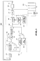
- FIG. 1 a block diagram of one embodiment of apparatus in accordance with the present invention for adjusting a digital signal, preferably a digital video signal, reproduced from a record medium to compensate, or pre-correct, for degradations that otherwise would be introduced into the reproduced video signal when it subsequently is subjected to analog processing.
- the illustrated apparatus implements a so-called multi-loop test wherein the deterioration of various characteristics of a video signal caused by successive dubbing, or re-recording thereof is detected.
- each incremental deterioration may not be perceptible, if the digital video signal is subjected to multiple dubbing and multiple conversions, a degraded video picture ultimately results.
- the apparatus illustrated in Figure 1 subjects a digital signal to multiple analog processing operations, whereupon the digital signal deteriorates in much the same manner as would occur if that digital signal had been converted to analog form, recorded as an analog signal, reconverted back into digital form, recorded as a digital signal, reproduced and converted into analog form once again, and so on, a multiple number of times. After M such analog processing operations, the deterioration in the digital signal may be more readily measured by detecting changes in predetermined characteristics thereof.
- the multi-loop test implemented by the digital signal adjusting apparatus shown in Figure 1 includes an analog input terminal 11, an ADC 20, a DAC 21, an analog output terminal 12, a feedback path 50, 51, BNC for interconnecting the analog output terminal 12 to the analog input terminal 11 and a digital video system 30.
- the digital video system includes digital video recording/playback apparatus in which digital video signals are recorded on a magnetic medium 36, such as magnetic tape, by a record/playback head 35. Digital video signals which subsequently are reproduced from the magnetic medium 36, converted to analog form and subjected to analog processing (such as analog recording or transmission) are subjected to deterioration; this deterioration is aggravated if several generations of recording or transmission are effected.
- the digital video system 30 operates to pre-correct, or compensate the digital video signal reproduced from the magnetic medium 36, prior to analog processing thereof, so as to reduce this deterioration, even if the digital video signal is subjected to several generations of analog processing.
- the digital video recording/reproducing apparatus included in the digital video system 30 includes an encoder 31 which is coupled to the ADC 20 to receive a digitized video signal that had been supplied to the analog input terminal 11 and to encode the digitized video signal in a conventional format.
- Examples of the digital recording format with which the encoder 31 operates are the conventional D-1 and D-2 formats.
- the output of the encoder 31 is coupled by way of a selector switch 33 to the head 35 via an equalizer amplifier 34. This equalizer amplifier 34 is convention.
- the digital video signals previously recorded on the magnetic medium 36 are reproduced by the head 35 and coupled to a decoder 37 which is compatible with the encoder 31 and operates in accordance with conventional formats, such as the D-1 or D-2 format. It will be appreciated, therefore, that the decoder 37 is of conventional construction.
- the output of the decoder 37 is coupled by way of a selector switch 38 to the DAC 21 via a signal adjuster 42.
- the purpose of this signal adjuster 42 is to provide the aforementioned compensation or pre-correction of the digital video signal reproduced from the magnetic medium 36.
- the signal adjuster 42 is adapted to provide one or more of the following adjustments to the digital video signal supplied thereto: a setup adjustment, a video gain adjustment, a chroma gain adjustment and a colour hue adjustment.
- a setup adjustment is adapted to adjust the black level included in the reproduced digital video signal to compensate for changes therein caused by analog processing.
- Video gain adjustment is adapted to adjust the video grey level in the reproduced digital video signal to compensate for changes therein caused by analog processing.
- Chroma gain adjustment is adapted to compensate for changes in the chrominance subcarrier, such as the usual burst signal, included in the digital video signal, as may be caused by analog processing.
- the multi-loop test arrangement is adapted to detect changes in a digital video signal that may be expected as a result of analog processing and thereby establish the aforementioned setup, video gain, chroma gain and colour hue adjustments for signal adjuster 42.
- the multi-loop test arrangement includes a test signal generator 32 which is adapted to generate digital test signals having one or more characteristics whose change caused by analog processing are to be detected.
- the test signal generator 32 operates to generate three distinctive test signals, one to establish the proper setup adjustment, another to establish the proper video gain adjustment and a third to establish the proper chroma gain adjustment. If desired, the test signal generator also may generate an additional test signal for use in establishing the colour hue adjustment.
- the test signal generator 32 is selectively coupled through the equalizer amplifier 34 to the decoder 37 and the signal adjuster 42 by the selector switch 33 when the illustrated apparatus operates in its test mode. It will be appreciated that, in this test mode, the digital test signal generated by the test signal generator 32 emulates the recording and playing back of a digital video signal, as when the digital video system operates in its record/playback mode. As an alternative, an analog test signal generator may be coupled to the analog input terminal 11 to supply analog test signals which are converted to digital form and used for the same purpose as the aforementioned digital test signals generated by the test signal generator 32.
- a digital test signal produced by, for example, the test signal generator 32 is coupled to the signal processing components of the digital video recorder included in the digital video system 30 (represented here merely by the equalizer amplifier 34 and the decoder 37) by way of the selector switch 33.
- the selector switch 38 couples the digital test signal through the signal adjuster 42 to the DAC 21 and the analog output terminal 12.
- the converted test signal is fed back from the analog output terminal 12 to the analog input terminal 11 by way of the analog circuits 50, such as an analog switcher, a terminal 51 and a conventional BNC cable (BNC cable is described in Harper, Handbook of Components for Electronics , 1977). This may be viewed as one pass, or circulation, of the digital test signal.
- the digital test signal is subjected to deterioration relative to the initial digital test signal because of the analog processing effected primarily by the ADC 20, the DAC 21 and the analog circuits 50. It is this deterioration which is detected and used to control the signal adjuster 42 so as to compensate or pre-correct the digital video signal subsequently reproduced from the magnetic medium 36.
- the selector switch 38 controls a loop switching operation.
- the digital test signal provided by the test signal generator 32 is selected by the switch 38, which engages its contact a , and thus is supplied as an input to the loop.
- the switch 38 is changed over to its contact b to connect the memory 39 into this loop.
- the digital test signal subjected to the analog processing of the ADC 20, the DAC 21 and the analog circuits 50, circulates through the loop.
- a detector 43 is coupled to the loop for detecting changes in the digital test signal as that signal circulates through the loop. As shown in Figure 1, the detector 43 is coupled to the output of the selector switch 38 and is adapted to detect changes after the digital test signal has circulated a predetermined number of times (for example, 20 times). As will be described below, the detector 43 includes temporary storage circuits, such as latch circuits, for storing the initial digital test signal generated by the test signal generator 32 and also the digital test signal after the Mth circulation thereof. Differences in these digital test signals are detected, and a change indication signal representative thereof is produced. As will be described, the operation carried out by the detector 43 is determined by whether the signal adjuster 42 is operating for setup adjustment, video gain adjustment, chroma gain adjustment or colour hue adjustment.
- An adjustment control data generator 44 is coupled to the detector 43 and is responsive to the change indication signal produced by the detector 43 for supplying adjustment control data to the signal adjuster 42.
- the adjustment control data generator 44 comprises an addressable memory, such as a read only memory (ROM) for storing different adjustment control data values which are addressed by the change indication signal supplied thereto by the detector 43.
- ROM read only memory
- the adjustment control data generator 44 may be implemented by a look-up table that is accessed by the detected change in the circulated digital test signal. It will be appreciated that this look-up table is adapted to store setup adjustment, video gain adjustment, chroma gain adjustment and colour hue adjustment data.
- a bar graph generator 40 which may be of a type known to those of ordinary skill in the art, is responsive to such indications to generate bar graph signals representing the number of times that the digital test signal circulates through the loop. This bar graph indicia is incremented in response to each circulation; and when the digital test signal has circulated M times, the bar graph generator is reset.
- a selector switch 41 which normally is coupled to the memory 39 by way of its contact a , is selectively changed over to its contact b so as to couple the bar graph signals generated by the bar graph generator 40 to the loop.
- the selector switch 41 is changed over from its contact a to contact b at predetermined times during each cycle of the digital test signal through the loop, thereby multiplexing, or superimposing, the bar graph signals onto the digital test signal.
- a display 60 such as a monitor, is coupled to the analog output terminal 12 to receive the signals provided thereat.
- digital video signals reproduced from the magnetic medium 36 are converted to analog form by the DAC 21 and coupled from the analog output terminal 12 to the display 60 whereat the video signals are displayed as a video picture.
- the digital test signal which circulates through the loop is converted to analog form by the DAC 21 and coupled from the analog output terminal 12 to the display 60 whereat the test signal is displayed.
- the test signal may include a conventional colour bar signal which (as shown in Figure 1) is displayed as colour bar display 61.
- other digital test signals may be displayed after they are converted to analog form.
- the display 60 also displays a bar graph indication 62 which is derived from the bar graph signals generated by the bar graph generator 40 as the digital test signal circulates through the loop. It will be appreciated that adjustments in the displayed test signal may be observed on the monitor as the signal adjuster 42 effects a setup adjustment, a video gain adjustment, a chroma gain adjustment or a colour hue adjustment. It will also be recognized that as the bar graph display 62 changes in response to each circulation of the digital test signal, such changes likewise may be observed.
- the test signal generator 32 generates digital samples of a video black level.
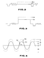
- the initial video black level test signal generated by the test signal generator is represented as the solid line BL O in Figure 2; and this initial black level test signal is supplied to the detector 43 by the selector switch 38 which engages its contact a .
- This black level test signal also is supplied by the switch 38 to the illustrated loop; and after the initial circulation thereof, the black level test signal is coupled to the memory 39 and the selector switch 38 changes over to engage its contact b .
- the black level test signal then circulates through the loop a total of M times, with each circulation serving to increment the bar graph indication generated by the bar graph generator 40.
- the black level test signal provided at the Mth circulation is represented as the broken line BL M in Figure 2.
- This change indication ⁇ S is supplied as an address to the adjustment control data generator 44 from which a video black level adjustment value is read and supplied to the signal adjuster 42 to compensate or correct for the detected change.
- each addressable location is adapted to store a respective adjustment value corresponding to the calculated change indication ⁇ S.
- a corresponding adjustment value is supplied to the signal adjuster 42. It will be appreciated that this adjustment value is used by the signal level adjuster not only to adjust the digital test signal supplied thereto during the test mode but also the digital video signal supplied thereto during a playback mode.
- the test signal generator 32 generates a video grey level test signal, such as video grey level samples. It will be appreciated that the test signal generator may operate first to generate the aforementioned black level test signal for a predetermined amount of time, followed by the grey level test signal. Alternatively, a suitable manual control, such as a selector switch, may be operated by a user to change over the type of test signal generated by the test signal generator 32. In any event, the grey level test signal initially produced by the test signal generator 32 is supplied by the selector switches 33 and 38 to the illustrated loop, and this initial grey level test signal GL O , as represented by the solid line in Figure 3, is coupled to the detector 43.
- a video grey level test signal such as video grey level samples.
- This grey level test signal is circulated through the loop M times, and it is expected that, as a result of the analog processing effected by the ADC 20, the DAC 21 and the analog circuits 50, the level of the grey level test signal GL M at the Mth circulation will be different from the initial grey level GL O as shown by the broken line in Figure 3.
- This change indication ⁇ V is supplied as an address to the adjustment control data generator 44 from which a video grey level adjustment value is read and supplied to the signal adjuster 42. Accordingly, the signal adjuster 42 is controlled to reduce the difference in the grey level shown in Figure 3 both from the grey level test signal supplied thereto during the test mode and for the digital video signal supplied thereto during a playback mode.
- the test signal generator 32 When carrying out a chroma gain adjustment operation, the test signal generator 32 generates digital samples of a single frequency test signal having a predetermined DC offset, such as shown by the solid waveform of Figure 4.
- the amplitude of this single frequency test signal may be represented as A O and its DC offset is represented as OS.
- the detector 43 and the adjustment control data generator 44 cooperate to supply adjustment control data to the signal adjuster 42 in response to a change ⁇ C in the amplitude of the single frequency test signal resulting from one circulation thereof.
- this ratio A M /A O is obtained by root sum square (RSS) processing of predetermined samples.
- This detected variation ⁇ C is used to address the look-up table which comprises the adjustment control data generator 44 to read therefrom a suitable adjustment control value corresponding to this detected variation ⁇ C.
- the signal adjuster 42 is controlled, or set, to adjust the single frequency test signal supplied thereto during a test mode and also to adjust the video signals supplied thereto during a playback mode to effect chroma gain adjustment. This reduces the change in the chroma gain of the reproduced digital video signal as would otherwise be caused by analog processing thereof, such as dubbing.
- the detector 43 operates to detect changes in the digital test signal after that signal has circulated through the loop M times, from which the change in the digital test signal caused by one circulation is determined. Then, the signal adjuster 42 is controlled, or set by adjustment control data produced by the adjustment control data generator 44 in response to the determined change so as to eliminate or at least minimize such change as far as is possible with this technique.
- This operation is applicable to a setup adjustment, a video gain adjustment or a chroma gain adjustment.
- a colour hue adjustment may be made in a similar manner.
- a latch circuit 72 schematically represented as a D-type latch circuit, includes a data input coupled to an input terminal 70 for receiving the digital test signal supplied thereto by the selector switch 38 shown in Figure 1.
- the latch circuit 72 includes a latch input coupled to a timing input terminal 71 which is adapted to receive a latch pulse when the digital test signal generated by the test signal generator 32 initially is supplied to the loop by the switch 38 and to receive another latch pulse after the digital test signal has circulated through the loop M times.
- the latch circuit 72 is illustrated as cascaded latch circuits 72a and 72b, wherein the latch circuit 72b is adapted to store temporarily the digital test signal initially supplied to the loop by the test signal generator 32 and the latch circuit 72a is adapted to store the digital test signal that has been circulated M times. It will be appreciated that the initial digital test signal first is stored in the latch circuit 72a in response to the initial latch pulse and then is shifted into the latch 72b in response to the latch pulse produced after the Mth circulation of the digital test signal.
- the detected change in the test signal ⁇ S or ⁇ V representing the change in the digital test signal following one circulation thereof through the loop, is coupled by way of a selector switch 72 to a ROM 74.
- This detected change ⁇ S or ⁇ V is used as an address for reading out from the ROM the particular adjustment control data stored at the addressed location.
- This adjustment control data is coupled to an output terminal 76 from which it is supplied to the signal adjuster 42.
- FIG. 5B illustrates, in somewhat greater detail, the manner in which the change in the digital test signal after that signal has circulated through the loop M times is detected.
- a processor 74a operates to implement equation 1 or equation 2, as may be selected.
- the latch circuit 72b supplies the processor 74a with the initial video black level signal BL O provided by the test signal generator 32 to the loop.
- the latch circuit 72a couples to the processor 74a the video black level signal BL M that has circulated through the loop M times.
- the processor determines the change ⁇ S in the video black level test signal for one circulation thereof and supplies this change ⁇ S as an address to ROM 74 from which corresponding adjustment control data is read and supplied to the signal adjuster 42.
- the latch circuit 72b stores the initial video grey level test signal GL O applied to the loop by the test signal generator 32; and the latch circuit 72a stores the video grey level test signal GL M that has circulated through the loop M times.
- These latched video grey level test signals are supplied to the processor 74a which processes the difference between these video grey level test signals in accordance with equation 2 to supply an address ⁇ V to the ROM 74, wherein ⁇ V corresponds to the change in the video grey level test signal produced during one circulation through the loop of the digital test signal.
- the latch circuit 72b stores samples D 01 and D 02 of the initial single frequency test signal applied to the loop by the test signal generator 32 and the latch circuit 72a stores the samples D M1 and D M2 from the single frequency signal that has circulated through the loop M times.
- change-over switch 73 supplies these respective samples to a root sum square circuit 75 which implements equation 3 to produce the address ⁇ C representing the change in the amplitude of the single frequency test signal.
- This address ⁇ C addresses the ROM 74 to read therefrom the corresponding adjustment control data which, in turn, is used to set the signal adjuster 42.
- the digital test signal is generated either by the test signal generator 32 or by an external source that is coupled to the analog input terminal 11. If an external source is used, that source may be of a conventional type, such as a conventional colour bar generator. Alternatively, a test signal, or successive test signals (such as the aforementioned video black level signal, video grey level signal and single frequency signal) may be recorded on the magnetic medium 36 and reproduced therefrom by the head 35 for coupling to the test loop.
- the signal adjuster 42 may be manually operated. To assist such manual operation, suitable indications of differences in the test signal after that signal has circulated through the loop M times may be provided. Alternatively, the display of the test signal, such as by the monitor 60, may be observed by the operator in effecting such manual adjustments.
- bar graph display 62 generated by the bar graph generator 40 has been described above, it will be appreciated that, if desired, other suitable displays of the number of circulations of the digital test signal through the test loop may be provided. For example, a numerical display indicative of the particular cycle of the digital test signal may be displayed.
- the digital video system 30 also may be operated so as to record each digital test signal that cycles through the test loop.
- the circulating digital test signal may be coupled by the selector switch 33 to the equalizer amplifier 34 and the recording head 35.
- a record of the circulating digital test signal including changes therein produced during each circulation, may be made. This record may be checked simply by playing back the magnetic medium 36.
- the superimposed bar graph signals, or other circulation indicating signals also may be recorded. Upon playback, a user thus may observe the degree of change in the digital test signal that is present during each respective cycle thereof through the test loop.
- the implementation of the detector 43 and the adjustment control generator 44 may be further modified in a manner to implement equations 1, 2 and 3 directly (i.e. without using a ROM or look-up table).
- the test signal generator 32 may generate other types of digital test signals which are useful in compensating or pre-correcting digital video signals from deterioration and degradation caused by conversion of those digital video signals to analog form and subsequent analog signal processing.
- M 20; although any other desired number of circulations of the digital test signal may be made for the purpose of detecting changes therein.
Landscapes
- Engineering & Computer Science (AREA)
- Signal Processing (AREA)
- Multimedia (AREA)
- Health & Medical Sciences (AREA)
- Biomedical Technology (AREA)
- General Health & Medical Sciences (AREA)
- Testing, Inspecting, Measuring Of Stereoscopic Televisions And Televisions (AREA)
- Television Signal Processing For Recording (AREA)
Claims (33)
- Gerät zur Einstellung eines von einem Aufzeichnungsmedium (36) wiedergegebenen und nach der Wiedergabe einer Analogverarbeitung unterworfenen Signals, bestehend auseiner Testeingabeeinrichtung (32; 11; 35;) zur Erzeugung eines Eingabetestsignalseiner Schleifeneinrichtung (20, 30, 21, 50) mit einer Digital-Analog-Wandlereinrichtung (21) und einer Analog-Digital-Wandlereinrichtung (20) zum M-maligen Zirkulieren des Testsignals durch die Schleifeneinrichtung, wobei M eine vorbestimmte Zahl ist, undeiner Detektoreinrichtung (43) zum Detektieren von Änderungen des Testsignals nach dem M-maligen Zirkulieren dieses Signals durch die Schleifeneinrichtung zur Erzeugung einer Änderungsanzeige (ΔS, ΔV, ΔC), gekennzeichnet durcheine automatische Einstellungseinrichtung (44, 42) mit einer adressierbaren Speichereinrichtung (74), die adressierbare Speicherstellen zum Speichern von Einstellungswerten aufweist, die durch die Änderungsanzeige zum Lesen eines korrespondierenden Einstellungswertes adressiert sind, wobei die automatische Einstellungseinrichtung auf den Einstellungswert anspricht und selektiv mit dem von dem Aufzeichnungsmedium wiedergegebenen Signal beaufschlagt wird, um vorbestimmte Charakteristiken des wiedergegebenen Signals einzustellen, und dadurch gekennzeichnet ist, daß das von dem Aufzeichnungsmedium wiedergegebene Signal ein digitales wiedergegebenes Signal und das Testsignal ein digitales Testsignal ist.
- Gerät nach Anspruch 1, wobei die automatische Einstellungseinrichtung (44, 42) in der Schleifeneinrichtung (20, 30, 21, 50) enthalten ist und selektiv mit dem digitalen Testsignal beaufschlagt wird, das durch die Schleifeneinrichtung zum Einstellen der vorbestimmten Charakteristiken in dieser Einrichtung zirkuliert.
- Gerät nach Anspruch 1 oder 2, wobei die Testeingabeeinrichtung einen Testsignalgenerator (32) zur Erzeugung eines Testsignals aufweist, das wenigstens eine der vorbestimmten Charakteristiken aufweist.
- Gerät nach Anspruch 3, wobei das digitale Testsignal ein Videoschwarzpegelsignal und die Detektoreinrichtung (43) eine Schwarzpegel-Detektoreinrichtung zum Detektieren einer Änderung des Videoschwarzpegelsignals nach dem M-maligen Zirkulieren des Videoschwarzpegelsignals durch die Schleifeneinrichtung (20, 30, 21, 50) aufweist.
- Gerät nach Anspruch 4, wobei die Schwarzpegeldetektoreinrichtung (43) eine Änderungsanzeige ΔS erzeugt, die durch
- Gerät nach Anspruch 4, wobei die Schwarzpegel-Detektoreinrichtung (43) eine Speichereinrichtung zum Speichern des vom Testsignalgenerator (32) bei einer Anfangszeit erzeugten Videoschwarzpegelsignals (BL0) und zum Speichern des M-mal durch die Schleifeneinrichtung (20, 30, 21, 50) zirkulierten Videoschwarzpegelsignals (BLM) und eine Vergleichseinrichtung zum Vergleichen der gespeicherten Videoschwarzpegelsignale miteinander aufweist.
- Gerät nach Anspruch 6, wobei die adressierbaren Speicherstellen in der adressierbaren Speichereinrichtung Videoschwarzpegel-Einstellungswerte speichern, und wobei die Vergleichseinrichtung für die Speichereinrichtung eine Adresse ΔS erzeugt, die durch
- Gerät nach Anspruch 7, wobei die Einstellungseinrichtung (44, 42) eine Pegeleinstellungseinrichtung zur Einstellung eines in einem von dem Aufzeichnungsmedium (36) wiedergegebenen digitalen Signal enthaltenen Videoschwarzpegels durch einen von ΔS bestimmten Betrag aufweist.
- Gerät nach Anspruch 3, wobei das digitale Testsignal ein Videograupegelsignal aufweist, und wobei die Detektoreinrichtung (43) eine Graupegel-Detektoreinrichtung zum Detektieren einer Änderung des Videograupegelsignals nach dem M-maligen Zirkulieren des Videograupegelsignals durch die Schleifeneinrichtung (20, 30, 21, 50) aufweist.
- Gerät nach Anspruch 9, wobei die Graupegel-Detektoreinrichtung (43) eine Änderungsanzeige ΔV erzeugt, die durch
- Gerät nach Anspruch 9, wobei die Graupegel-Detektoreinrichtung (43) eine Speichereinrichtung zum Speichern des vom Testsignalgenerator (32) bei einer Anfangszeit erzeugten Videograupegelsignals (GL0) und zum Speichern des M-mal durch die Schleifeneinrichtung (20, 30, 21, 50) zirkulierten Videograupegelsignals (GLM) und eine Vergleichseinrichtung zum Vergleichen der gespeicherten Videograupegelsignale miteinander aufweist.
- Gerät nach Anspruch 11, wobei die adressierbaren Speicherstellen in der adressierbaren Speichereinrichtung Videograupegel-Einstellungswerte speichern, und wobei die Vergleichseinrichtung für die Speichereinrichtung eine Adresse ΔV erzeugt, die durch
- Gerät nach Anspruch 12, wobei die Einstellungseinrichtung (42) eine Graupegel-Einstellungseinrichtung zum Einstellen eines in einem von dem Aufzeichnungsmedium (36) wiedergegebenen digitalen Signal enthaltenen Videograupegels um einen von ΔV bestimmten Betrag aufweist.
- Gerät nach Anspruch 3, wobei das digitale Testsignal Samples eines Einzelfrequenzsignals mit einer vorbestimmten Gleichsignalverschiebung (OS) aufweist, und wobei die Detektoreinrichtung (43) eine Sampleänderungseinrichtung zum Detektieren einer Änderung der Samples nach dem M-maligen Zirkulieren der Samples durch die Schleifeneinrichtung (20, 30, 21, 50) aufweist.
- Gerät nach Anspruch 14, wobei die Sampleänderungseinrichtung eine Änderungsanzeige ΔC erzeugt, die durch
- Gerät nach Anspruch 14, wobei die Sampleänderungseinrichtung eine Speichereinrichtung zum Speichern vorbestimmter Samples des vom Testsignalgenerator (32) bei einer Anfangszeit erzeugten Einzelfrequenzsignals und zum Speichern der M-mal durch die Schleifeneinrichtung (20, 30, 21, 50) zirkulierten, im wesentlichen gleichen vorbestimmten Samples, und eine Quadratsummen-Verarbeitungseinrichtung (75) zum Abtasten einer Änderung ΔC der gespeicherten Samples aufweist, die durch
- Gerät nach Anspruch 16, wobei die adressierbaren Speicherstellen in der adressierbaren Speichereinrichtung Pegeleinstellungswerte speichern und wobei eine Einrichtung zum Zuführen der abgetasteten Änderung ΔC als eine Adresse zur adressierbaren Speichereinrichtung zum Lesen eines korrespondierenden Pegeleinstellungswertes aus der Speichereinrichtung und eine Pegeleinstellungseinrichtung (44, 42) zum Einstellen eines vom Aufzeichnungsmedium (36) wiedergegebenen digitalen Signals durch den aus der adressierbaren Speichereinrichtung gelesenen Pegeleinstellungswert vorhanden sind.
- Gerät nach Anspruch 3, wobei das digitale Testsignal ein Videoschwarzpegelsignal darstellt, und wobei die automatische Einstellungseinrichtung (44,42) eine Schwarzabhebungs-Einstellungseinrichtung zum Einstellen eines Schwarzpegels in dem vom Aufzeichnungsmedium (36) wiedergegebenen digitalen Signal als eine Funktion von in dem digitalen Testsignal nach dem M-maligen Zirkulieren dieses Signals durch die Schleifeneinrichtung (20, 30, 21, 50) detektierten Änderungen aufweist.
- Gerät nach Anspruch 3, wobei das digitale Testsignal ein Videograupegelsignal darstellt, und wobei die automatische Einstellungseinrichtung (44,42) eine Videoverstärkungs-Einstellungseinrichtung zur Einstellung eines Graupegels in dem vom Aufzeichnungsmedium (36) wiedergegebenen digitalen Signal als eine Funktion von in dem digitalen Testsignal nach dem M-maligen Zirkulieren dieses Signals durch die Schleifeneinrichtung (20, 30, 21, 50) detektierten Änderungen aufweist.
- Gerät nach Anspruch 3, wobei das digitale Testsignal ein Einzelfrequenzsignal darstellt, und wobei die automatische Einstellungseinrichtung (44,42) eine Chromaverstärkungs-Einstellungseinrichtung zur Einstellung einer Chromaverstärkung in dem vom Aufzeichnungsmedium (36) wiedergegebenen digitalen Signal als eine Funktion von in dem digitalen Testsignal nach dem M-maligen Zirkulieren dieses Signals durch die Schleifeneinrichtung (20, 30, 21, 50) detektierten Änderungen aufweist.
- Gerät nach einem der vorhergehenden Ansprüche, wobei die Schleifeneinrichtung (20, 30, 21, 50) eine Selektorschaltereinrichtung (38) zum Selektiven Koppeln der Testeingabeeinrichtung (32; 11; 35) an die Schleifeneinrichtung für eine Anfangszirkulation des digitalen Testsignals durch die Schleifeneinrichtung aufweist.
- Gerät nach einem der vorhergehenden Ansprüche, wobei die Testeingabeeinrichtung (32; 11; 35) eine Signalwiedergabeeinrichtung (35) zum Wiedergeben eines auf dem Aufzeichnungsmedium (36) aufgezeichneten digitalen Testsignals aufweist.
- Gerät nach einem der vorhergehenden Ansprüche, wobei die Schleifeneinrichtung (20, 30, 21, 50) zum Verhindern einer Oszillation der Schleifeneinrichtung eine Speichereinrichtung (39) zum zeitweiligen Speichern des digitalen Testsignals aufweist.
- Gerät nach Anspruch 21 und 22, wobei die Selektorschaltereinrichtung (38) selektiv an die Testeingabeeinrichtung (32; 11; 35) oder an die Speichereinrichtung (39) zum Zirkulieren des von der Testeingabeeinrichtung erzeugten digitalen Testsignals oder des zeitweilig gespeicherten digitalen Testsignals gekoppelt ist.
- Gerät nach einem der vorhergehenden Ansprüche, mit einer an die Digital-Analog-Wandlereinrichtung (21) der Schleifeneinrichtung (20, 30, 21, 50) gekoppelten Anzeigeeinrichtung (60) zum Anzeigen eines von einem von dem Aufzeichnungsmedium wiedergegebenen digitalen Signal abgeleiteten Videobildes und einer an die Schleifeneinrichtung gekoppelten Zirkulationsanzeigeeinrichtung (40; 41) zum Abtasten der Zahl der Zirkulationen des digitalen Testsignals durch die Schleifeneinrichtung und zum Zuführen einer Anzeige (62) dieser Zahl zur Anzeigeeinrichtung für eine Anzeige.
- Gerät nach Anspruch 25, wobei die Zirkulationsanzeigeeinrichtung eine Strichgraph-Erzeugungseinrichtung (40) zur Erzeugung von Strichgraph-Anzeigesignalen, welche darstellen, wie oft mal das digitale Testsignal durch die Schleifeneinrichtung zirkuliert ist, und eine Einrichtung (41) zum Koppeln der Strichgraph-Anzeigesignale an die Anzeigeeinrichtung (60) aufweist.
- Gerät nach Anspruch 23, mit einer Schaltereinrichtung (41) zum selektiven Koppeln der Speichereinrichtung (39) oder der Strichgraph -Erzeugungseinrichtung (40) an die Digital-Analog-Wandlereinrichtung (21).
- Gerät nach Anspruch 1, miteiner an die Schleifeneinrichtung gekoppelten Zirkulationsanzeigeeinrichtung (40, 41) zum Abtasten der Zahl der Zirkulationen des digitalen Testsignals durch die Schleifeneinrichtung zur Erzeugung eines diese Zahl anzeigenden Anzeigesignals,einer an die Schleifeneinrichtung gekoppelten Anzeigeeinrichtung (60) zum selektiven Empfangen und Anzeigen eines nach seiner Wiedergabe vom Aufzeichnungsmedium durch die automatische Einstellungseinrichtung eingestellten Videosignals, des digitalen Testsignals und des Anzeigesignals, undeiner Modusauswahleinrichtung zum Auswählen eines Wiedergabemodus zum Zuführen eines vom Aufzeichnungsmedium wiedergegebenen Videosignals zur Einstellungseinrichtung und zum Auswählen eines Testmodus zum Verbinden der Schleifeneinrichtung mit der Einstellungseinrichtung und zum Koppeln der Quelle und der Zirkulationsanzeigeeinrichtung an die Schleifeneinrichtung, wobei das digitale Testsignal zirkuliert und eine Anzeige der Zahl der Zirkulationen angezeigt wird.
- Gerät nach Anspruch 28, wobei die Modusauswahleinrichtung eine Selektorschaltereinrichtung (33, 41, 38) zum Koppeln der Quelle an die Schleifeneinrichtung (20, 30, 21, 50) und zum selektiven Koppeln der Zirkulationsanzeigeeinrichtung (40) an die Schleifeneinrichtung während nur eines Teils einer Zirkulationsperiode aufweist.
- Gerät nach Anspruch 29, wobei die Selektorschaltereinrichtung (33, 41, 38) in einem Wiedergabemodus zur Unterbrechnung der Schleifeneinrichtung (20, 30, 21, 50) und zum Koppeln des vom Aufzeichnungsmedium wiedergegebenen Videosignals an die Einstellungseinrichtung (44, 42) arbeitet.
- Gerät nach einem der Ansprüche 28, 29 oder 30, wobei die Quelle einen Videosignalgenerator (32) zum Erzeugen eines digitalen Videotestsignals aufweist, und wobei die Anzeigeeinrichtung (60) das Videotestsignal (61) und das ihm überlagerte Anzeigesignal (62) anzeigt.
- Gerät nach Anspruch 31, wobei der Videosignalgenerator (32) einen Farbstrichgenerator aufweist.
- Gerät nach einem der Ansprüche 28, 29, 30, 31 oder 32, wobei die Zirkulationsanzeigeeinrichtung eine Strichgraph-Erzeugungseinrichtung (40) zur Erzeugung von Strichgraphsignalen für eine Anzeige durch die Anzeigeeinrichtung (60) aufweist, um die Zahl der Zirkulationen des digitale Testsignals durch die Schleifeneinrichtung anzuzeigen.
Applications Claiming Priority (2)
| Application Number | Priority Date | Filing Date | Title |
|---|---|---|---|
| JP163291/91 | 1991-04-11 | ||
| JP03163291A JP3141429B2 (ja) | 1991-04-11 | 1991-04-11 | 記録再生装置の映像調整装置 |
Publications (3)
| Publication Number | Publication Date |
|---|---|
| EP0508768A2 EP0508768A2 (de) | 1992-10-14 |
| EP0508768A3 EP0508768A3 (en) | 1994-06-08 |
| EP0508768B1 true EP0508768B1 (de) | 1998-06-17 |
Family
ID=15771035
Family Applications (1)
| Application Number | Title | Priority Date | Filing Date |
|---|---|---|---|
| EP92303149A Expired - Lifetime EP0508768B1 (de) | 1991-04-11 | 1992-04-09 | Gerät zur Einstellung eines wiedergegebenen Signals |
Country Status (5)
| Country | Link |
|---|---|
| US (1) | US5557417A (de) |
| EP (1) | EP0508768B1 (de) |
| JP (1) | JP3141429B2 (de) |
| KR (1) | KR100268622B1 (de) |
| DE (1) | DE69225922T2 (de) |
Families Citing this family (11)
| Publication number | Priority date | Publication date | Assignee | Title |
|---|---|---|---|---|
| DE69231762T2 (de) | 1991-07-08 | 2001-07-26 | Seiko Epson Corp., Tokio/Tokyo | Risc-prozessor mit dehnbarer architektur |
| KR0138889B1 (ko) * | 1993-01-14 | 1998-06-01 | 김광호 | 비디오 테이프의 속도증가에 따른 화면서치 오동작 방지회로 |
| US6243139B1 (en) * | 1993-12-22 | 2001-06-05 | Canon Kabushiki Kaisha | Apparatus for block-encoding input image signals |
| US6337710B1 (en) * | 1997-06-12 | 2002-01-08 | Lsi Logic Corporation | Graphical video editing system for regeneration of bitstreams |
| US5939873A (en) * | 1997-11-13 | 1999-08-17 | Sony Corporation | Test fixture for a liquid recirculation unit |
| US6801246B2 (en) | 2001-02-27 | 2004-10-05 | Thomson Licensing, S.A. | Method and apparatus for detecting change in video source material |
| GB2379115A (en) * | 2001-08-21 | 2003-02-26 | Sony Uk Ltd | Introducing test signals into a data signal |
| GB2379114A (en) * | 2001-08-21 | 2003-02-26 | Sony Uk Ltd | Introducing test signals into a data signal |
| US7292062B2 (en) * | 2005-05-02 | 2007-11-06 | Infineon Technologies, Ag | Distribution of signals throughout a spine of an integrated circuit |
| US20070143185A1 (en) * | 2005-12-12 | 2007-06-21 | Harmon Richard M | Systems and Methods for Allocating a Consumer Access Right to a Live Event |
| US9137505B2 (en) * | 2013-02-06 | 2015-09-15 | C&C Technic Taiwan Co., Ltd. | Long-range VGA image transmission system providing automatic image adjustment |
Family Cites Families (7)
| Publication number | Priority date | Publication date | Assignee | Title |
|---|---|---|---|---|
| JPS503111A (de) * | 1973-06-08 | 1975-01-14 | ||
| US4325080A (en) * | 1979-04-24 | 1982-04-13 | Olympus Optical Co., Ltd. | Apparatus for displaying video track number in viewfinder of video camera |
| WO1987006420A1 (en) * | 1986-04-11 | 1987-10-22 | Ampex Corporation | Method and apparatus for adjusting video record and reproduce systems |
| US4998171A (en) * | 1988-07-05 | 1991-03-05 | Samsung Electronics Co., Ltd. | Automatic shift circuit for a sub-picture screen for picture-in-picture feature |
| US5070495A (en) * | 1989-04-12 | 1991-12-03 | International Business Machines Corporation | Write calibration for magnetooptic disk recorders |
| DE58907127D1 (de) * | 1989-08-22 | 1994-04-07 | Itt Ind Gmbh Deutsche | Fernsehempfänger mit positionsgesteuerter Fernbedienung. |
| NL9000327A (nl) * | 1990-02-12 | 1991-09-02 | Philips Nv | Informatieoptekeninrichting. |
-
1991
- 1991-04-11 JP JP03163291A patent/JP3141429B2/ja not_active Expired - Fee Related
-
1992
- 1992-04-09 EP EP92303149A patent/EP0508768B1/de not_active Expired - Lifetime
- 1992-04-09 DE DE69225922T patent/DE69225922T2/de not_active Expired - Fee Related
- 1992-04-09 KR KR1019920005887A patent/KR100268622B1/ko not_active Expired - Fee Related
-
1994
- 1994-01-24 US US08/185,754 patent/US5557417A/en not_active Expired - Lifetime
Also Published As
| Publication number | Publication date |
|---|---|
| DE69225922T2 (de) | 1998-10-15 |
| DE69225922D1 (de) | 1998-07-23 |
| US5557417A (en) | 1996-09-17 |
| KR100268622B1 (ko) | 2000-10-16 |
| JPH04313981A (ja) | 1992-11-05 |
| EP0508768A3 (en) | 1994-06-08 |
| JP3141429B2 (ja) | 2001-03-05 |
| EP0508768A2 (de) | 1992-10-14 |
| KR920020458A (ko) | 1992-11-21 |
Similar Documents
| Publication | Publication Date | Title |
|---|---|---|
| US5557417A (en) | Multi-loop testing apparatus with means for adjusting a reproduced video signal | |
| US4700239A (en) | Differential gain and differential phase compensator circuit of a video signal | |
| US4321619A (en) | Second order velocity error correction for time base correctors | |
| KR910002157B1 (ko) | 순차 주사 텔레비젼 장치 | |
| US5144453A (en) | Apparatus for delaying longitudinal time code signal for digital video tape recorder | |
| US4686583A (en) | Dropout compensating apparatus using a digital delay circuit | |
| US5260784A (en) | Multi-loop testing apparatus with field memory | |
| US5353117A (en) | Vertical interval test signal for detecting video system low-level luminance linearity and differential gain and phase errors | |
| EP0414556B1 (de) | Ausgleichsschaltung zum Verzerrungsausgleich eines Videosignals durch die Verzerrungsbestimmung eines Rampensignals in dem Videosignal | |
| US4890158A (en) | Recursive noise reduction filter for video test apparatus | |
| EP0285078B1 (de) | Verfahren und Vorrichtung zur Eichung der Phase eines Videosignals | |
| EP0217091A1 (de) | Korrekturkreis für Geschwindigkeitsfehler in einem Zeitbasiskorrektor | |
| US5438558A (en) | Image signal apparatus including clamping processing of image signal | |
| JP2734518B2 (ja) | テレビジョンカメラ一体型磁気記録装置 | |
| US5099312A (en) | Timebase corrector | |
| KR0138142B1 (ko) | 화질보상회로 | |
| KR0132228Y1 (ko) | 노이즈 바 고정장치 | |
| JPS6118276A (ja) | 再生装置 | |
| JP2593727B2 (ja) | ドロップアウト補償回路検査用の記録媒体作成装置およびこの装置によって作成された記録媒体 | |
| US5283660A (en) | Video signal processing apparatus having timebase corrector and means for replacing residual error data with specific data | |
| JP3036888B2 (ja) | ビデオプリンタのモニタ出力処理回路調整方法 | |
| JPH0533878B2 (de) | ||
| EP0778701B1 (de) | Schaltung und Verfahren zur Erhöhung der Vertikalausdehnung eines Bildes bei Wiedergabe eines PAL-Plus Signales durch einen VCR | |
| JP3155163B2 (ja) | 映像信号再生装置 | |
| JPH0558318B2 (de) |
Legal Events
| Date | Code | Title | Description |
|---|---|---|---|
| PUAI | Public reference made under article 153(3) epc to a published international application that has entered the european phase |
Free format text: ORIGINAL CODE: 0009012 |
|
| AK | Designated contracting states |
Kind code of ref document: A2 Designated state(s): DE FR GB |
|
| PUAL | Search report despatched |
Free format text: ORIGINAL CODE: 0009013 |
|
| AK | Designated contracting states |
Kind code of ref document: A3 Designated state(s): DE FR GB |
|
| 17P | Request for examination filed |
Effective date: 19941021 |
|
| 17Q | First examination report despatched |
Effective date: 19961023 |
|
| GRAG | Despatch of communication of intention to grant |
Free format text: ORIGINAL CODE: EPIDOS AGRA |
|
| GRAG | Despatch of communication of intention to grant |
Free format text: ORIGINAL CODE: EPIDOS AGRA |
|
| GRAH | Despatch of communication of intention to grant a patent |
Free format text: ORIGINAL CODE: EPIDOS IGRA |
|
| GRAH | Despatch of communication of intention to grant a patent |
Free format text: ORIGINAL CODE: EPIDOS IGRA |
|
| GRAA | (expected) grant |
Free format text: ORIGINAL CODE: 0009210 |
|
| AK | Designated contracting states |
Kind code of ref document: B1 Designated state(s): DE FR GB |
|
| REF | Corresponds to: |
Ref document number: 69225922 Country of ref document: DE Date of ref document: 19980723 |
|
| ET | Fr: translation filed | ||
| PLBE | No opposition filed within time limit |
Free format text: ORIGINAL CODE: 0009261 |
|
| STAA | Information on the status of an ep patent application or granted ep patent |
Free format text: STATUS: NO OPPOSITION FILED WITHIN TIME LIMIT |
|
| 26N | No opposition filed | ||
| REG | Reference to a national code |
Ref country code: GB Ref legal event code: IF02 |
|
| PGFP | Annual fee paid to national office [announced via postgrant information from national office to epo] |
Ref country code: FR Payment date: 20090417 Year of fee payment: 18 Ref country code: DE Payment date: 20090402 Year of fee payment: 18 |
|
| PGFP | Annual fee paid to national office [announced via postgrant information from national office to epo] |
Ref country code: GB Payment date: 20090408 Year of fee payment: 18 |
|
| GBPC | Gb: european patent ceased through non-payment of renewal fee |
Effective date: 20100409 |
|
| REG | Reference to a national code |
Ref country code: FR Ref legal event code: ST Effective date: 20101230 |
|
| PG25 | Lapsed in a contracting state [announced via postgrant information from national office to epo] |
Ref country code: DE Free format text: LAPSE BECAUSE OF NON-PAYMENT OF DUE FEES Effective date: 20101103 |
|
| PG25 | Lapsed in a contracting state [announced via postgrant information from national office to epo] |
Ref country code: GB Free format text: LAPSE BECAUSE OF NON-PAYMENT OF DUE FEES Effective date: 20100409 |
|
| PG25 | Lapsed in a contracting state [announced via postgrant information from national office to epo] |
Ref country code: FR Free format text: LAPSE BECAUSE OF NON-PAYMENT OF DUE FEES Effective date: 20100430 |