EP0508481A2 - Verfahren und Schaltung zum Schutz einer Plasmadüse - Google Patents
Verfahren und Schaltung zum Schutz einer Plasmadüse Download PDFInfo
- Publication number
- EP0508481A2 EP0508481A2 EP92106308A EP92106308A EP0508481A2 EP 0508481 A2 EP0508481 A2 EP 0508481A2 EP 92106308 A EP92106308 A EP 92106308A EP 92106308 A EP92106308 A EP 92106308A EP 0508481 A2 EP0508481 A2 EP 0508481A2
- Authority
- EP
- European Patent Office
- Prior art keywords
- nozzle
- workpiece
- voltage
- current
- mode
- Prior art date
- Legal status (The legal status is an assumption and is not a legal conclusion. Google has not performed a legal analysis and makes no representation as to the accuracy of the status listed.)
- Withdrawn
Links
- 238000000034 method Methods 0.000 title claims abstract description 33
- 230000000670 limiting effect Effects 0.000 claims description 10
- 238000001514 detection method Methods 0.000 claims description 9
- 230000004044 response Effects 0.000 claims description 2
- 238000005520 cutting process Methods 0.000 description 47
- 239000002184 metal Substances 0.000 description 27
- 229910052751 metal Inorganic materials 0.000 description 27
- 230000006378 damage Effects 0.000 description 16
- 239000007789 gas Substances 0.000 description 15
- 230000009471 action Effects 0.000 description 7
- 230000036961 partial effect Effects 0.000 description 6
- 230000002829 reductive effect Effects 0.000 description 6
- 230000006866 deterioration Effects 0.000 description 4
- 238000010586 diagram Methods 0.000 description 4
- 230000001681 protective effect Effects 0.000 description 4
- 238000012544 monitoring process Methods 0.000 description 3
- 230000002411 adverse Effects 0.000 description 2
- 230000001066 destructive effect Effects 0.000 description 2
- 230000003628 erosive effect Effects 0.000 description 2
- 230000001965 increasing effect Effects 0.000 description 2
- 238000002844 melting Methods 0.000 description 2
- 230000008018 melting Effects 0.000 description 2
- 238000012986 modification Methods 0.000 description 2
- 230000004048 modification Effects 0.000 description 2
- RYGMFSIKBFXOCR-UHFFFAOYSA-N Copper Chemical compound [Cu] RYGMFSIKBFXOCR-UHFFFAOYSA-N 0.000 description 1
- 238000013459 approach Methods 0.000 description 1
- 239000002826 coolant Substances 0.000 description 1
- 229910052802 copper Inorganic materials 0.000 description 1
- 239000010949 copper Substances 0.000 description 1
- 230000003247 decreasing effect Effects 0.000 description 1
- 230000001627 detrimental effect Effects 0.000 description 1
- 238000006073 displacement reaction Methods 0.000 description 1
- 230000000694 effects Effects 0.000 description 1
- 230000002708 enhancing effect Effects 0.000 description 1
- 238000010438 heat treatment Methods 0.000 description 1
- 238000010348 incorporation Methods 0.000 description 1
- 239000000463 material Substances 0.000 description 1
- 238000011017 operating method Methods 0.000 description 1
- 230000003287 optical effect Effects 0.000 description 1
- 230000009467 reduction Effects 0.000 description 1
- 239000007787 solid Substances 0.000 description 1
- 230000002459 sustained effect Effects 0.000 description 1
- XLYOFNOQVPJJNP-UHFFFAOYSA-N water Substances O XLYOFNOQVPJJNP-UHFFFAOYSA-N 0.000 description 1
Images


Classifications
-
- B—PERFORMING OPERATIONS; TRANSPORTING
- B23—MACHINE TOOLS; METAL-WORKING NOT OTHERWISE PROVIDED FOR
- B23K—SOLDERING OR UNSOLDERING; WELDING; CLADDING OR PLATING BY SOLDERING OR WELDING; CUTTING BY APPLYING HEAT LOCALLY, e.g. FLAME CUTTING; WORKING BY LASER BEAM
- B23K10/00—Welding or cutting by means of a plasma
- B23K10/006—Control circuits therefor
-
- H—ELECTRICITY
- H05—ELECTRIC TECHNIQUES NOT OTHERWISE PROVIDED FOR
- H05H—PLASMA TECHNIQUE; PRODUCTION OF ACCELERATED ELECTRICALLY-CHARGED PARTICLES OR OF NEUTRONS; PRODUCTION OR ACCELERATION OF NEUTRAL MOLECULAR OR ATOMIC BEAMS
- H05H1/00—Generating plasma; Handling plasma
- H05H1/24—Generating plasma
- H05H1/26—Plasma torches
- H05H1/32—Plasma torches using an arc
- H05H1/34—Details, e.g. electrodes, nozzles
- H05H1/36—Circuit arrangements
-
- H—ELECTRICITY
- H05—ELECTRIC TECHNIQUES NOT OTHERWISE PROVIDED FOR
- H05H—PLASMA TECHNIQUE; PRODUCTION OF ACCELERATED ELECTRICALLY-CHARGED PARTICLES OR OF NEUTRONS; PRODUCTION OR ACCELERATION OF NEUTRAL MOLECULAR OR ATOMIC BEAMS
- H05H1/00—Generating plasma; Handling plasma
- H05H1/24—Generating plasma
- H05H1/26—Plasma torches
- H05H1/32—Plasma torches using an arc
- H05H1/34—Details, e.g. electrodes, nozzles
- H05H1/3494—Means for controlling discharge parameters
Definitions
- the present invention relates to the art of plasma torches of the type including an electrode within a cavity of a nozzle and employing electric energy for establishing an arc between the electrode and nozzle to maintain a plasma issuing from the nozzle, and more particularly, to a system, method and circuit for protecting the nozzle of the plasma torch.
- a large variety of plasma torch designs has been used in the past. These designs employ a nozzle with a generally cylindrical cavity receiving a generally cylindrical electrode with a power supply providing current for establishing an arc between the electrode and nozzle. This type of nozzle is shown in Blankenship 4,929,811. Since plasma arc torches involve electrical current, a variety of protection circuits are employed. One of these circuits is illustrated in Blankenship 4,929,811. Another electrical protection circuit is illustrated in Dallavale 4,987,285. Both of these prior patents are incorporated by reference herein for background information applicable to the present invention and so that details of the plasma torch technology need not be repeated.
- Plasma arc torches are employed for cutting metal of various thicknesses. These plasma cutting torches involve an electrode within a cylindrical cavity of a nozzle having an outlet through which the plasma column issues after being established in the annular passageway between the electrode and nozzle. Electrical energy established by a voltage differential between the electrode and nozzle creates an arc in the nozzle for ionizing the gas before it passes from the outlet of the nozzle toward the workpiece, normally metal.
- the material being cut is conductive and has a variety of thicknesses.
- the plasma cutting process creates ionized gases within the annular chamber between the nozzle and electrode which establishes and maintains the plasma arc column due to the energy provided by the power supply connected between the nozzle and electrode and between the nozzle and the workpiece.
- a vortex action of the plasma gas passing through the annular chamber in the nozzle is caused by forcing the gas through a plurality of holes leading to the gas passageway.
- the swirling gas is focused in the nozzle chamber where it can be ionized and discharged through the small orifice or outlet of the nozzle.
- the nozzle of the plasma torch is often dragged directly over and in contact with the metal.
- the torch is operated in a low current mode which maintains a current in the range of about 35-50 amperes, which is at a set point sufficient to sustain a stable arc and to obtain realistic traveling speeds and cutting quality.
- the low current mode of operation does not cause substantial nozzle damage even when the conductive nozzle is dragged along the conductive metal workpiece with the arc extending through the nozzle opening.
- the low current causes a lower energy and, thus, does not substantially overheat the nozzle.
- the plasma torch is operated in a high current mode wherein the power supply is set at a current level over 75 amperes. With this high current flow necessary to sustain a focused arc plasma sufficiently powerful to cut a relatively thick workpiece, the nozzle itself must be maintained above the conductive workpiece so that the nozzle does not contact the workpiece and allow the arc to attach to the nozzle.
- an operator maintains the nozzle at least about .100-.125 inches from the metal workpiece being cut by the moving plasma torch as the torch is operated in a high current mode.
- the relationship between the arc current supplied to the torch and the thickness of the metal being cut is generally set so that the ratio of the arc current amperes divided by 100 equals the thickness of the plate which can be cut.
- a metal plate of 0.40 can be cut efficiently by the moving plasma torch.
- the torch can be operated with the nozzle in contact with and being dragged along the workpiece.
- the arc current is set at the power supply to be in the high current mode, which mode exceeds about 75 amperes.
- the high current mode is generally above 40-50 amperes and preferably above about 25 amperes.
- Rapid damage to the nozzle causes persons to feel that plasma cutting of metal is not economical. Consequently, in many instances the plasma cutting torch is believed to be too fragile for cutting thick plate, when the problem is not the normal wear of the torch itself, but improper operation of the plasma cutting torch by contacting or dragging the nozzle along the workpiece.
- High arc current is normally required in bevel cutting because of the substantial distance between the workpiece and the outlet of the nozzle. With the torch held at an angle there is a higher probability that the corner of the nozzle will contact the workpiece during bevel cutting. This propensity to contact the workpiece increases the probability of causing the arc to attach to the nozzle. This will destroy the nozzle quite rapidly. Such rapid destruction of the nozzle is more severe in the higher current mode of operation. Also, continuous dragging of the nozzle along the workpiece while operating at high power will damage the torch itself. However, this torch damage occurs slower than nozzle failure.
- An operator should know that in the higher current mode of operation a spacing must be maintained between the torch and the workpiece. In addition, the operator should know that if the nozzle is being powered in the high arc current mode when the torch is laid on a grounded plate damage to the nozzle will be caused immediately. Indeed, the nozzle can be melted in this situation. At the lower current operating modes, the arc current is not sufficient to increase the temperature of the nozzle to a melting point temperature. The workpiece or plate will produce a sufficient heat sink to prevent damage to the torch when it is placed on a grounded plate while being operated or driven by power supply in the low arc current mode of operation.
- the nozzle voltage is monitored to detect when the nozzle is being dragged along, or in contact with, the workpiece or metal plate being cut. If the nozzle is being dragged along the plate while being operated in the high current mode of operation, the power supply is shifted to a low current mode of operation with the arc current being held at a lower level, such as about 40 amperes. In the alternative, the power supply is prevented from increasing the current above a lower level, such as 40 amperes.
- the monitored voltage senses this condition and allows the power supply to be shifted to the high current mode of operation.
- the plasma power supply is shifted back to the set value for high current operation. In this manner, damage to the nozzle of the plasma torch is prevented or reduced when the nozzle contacts the workpiece during high current operating conditions.
- This invention has been used successful with a 125 ampere Lincoln Magnum PCT 125 torch powered by a Pro-Cut 125 power supply with a normal phase back input control.
- the monitoring circuit detected contact of the plasma torch nozzle with the workpiece, the power supply current was reduced from a set point of 125 amperes down to a low current mode of operation at a current level of 40 amperes.
- This reduced current maintained the arc but substantially reduced the damage to the nozzle due to contact with the workpiece.
- Reduction of the nozzle voltage to the grounded voltage of the workpiece indicates that the nozzle is touching the workpiece.
- the present invention monitors the voltage of the nozzle. As the nozzle voltage approaches the workpiece voltage, i.e. ground, the power supply is phased back to shift the arc current from 125 amperes to 40 amperes.
- the operation of the plasma torch is not interrupted upon detection of contact between the nozzle and workpiece.
- the input rectifier of the power supply is merely phased back to the lower arc current mode, which is approximately 40 amperes in the preferred embodiment. Otherwise, the torch is operated in the high current mode which is at any set point substantially above the 40 ampere lower current level.
- the torch is not turned off, which action would extinguish the plasma creating arc. Such an action would adversely affect the metal cutting operation. In some instances an abrupt shut down of the torch would surprise the operator and would require that the operator restart the torch by actuating the torch trigger.
- the operator will know when the power supply is a shift from the high current mode of operation to the low current mode upon contact between the nozzle and workpiece; therefore, the operator merely withdraws the torch slightly from the workpiece. This minor action establishes a space between the nozzle and workpiece, which immediately shifts the operation of the power supply back to the set point of the high current mode of operation.
- This high current operation is controlled by the current set point of the power supply. This power supply set point can be adjusted for different thicknesses of metal being cut.
- the arc current supplied to the torch is the current which passes between the electrode and the nozzle or workpiece for sustaining the plasma as the swirling gas moves through the nozzle toward the outlet of the nozzle. This current controls the energy available for the arc plasma cutting.
- a circuit for protecting the nozzle of a plasma arc torch as it is operated at a high set point current which circuit comprises means for sensing the voltage at the nozzle, means for comparing the nozzle voltage with a reference voltage and means for limiting or reducing the arc current to the torch when the nozzle voltage is within a selected range of the reference voltage.
- the reference voltage is the voltage of the workpiece, which is normally grounded.
- the range or threshold is less than 5.0 volts.
- the nozzle voltage is in the general range of -60/-120 volts D.C. This provides approximately 60 volts between the reference voltage and the nozzle voltage.
- This second mode of operation can be defined as a low, non-destructive current in the range of 35-50 amperes.
- This system includes means for detecting contact of the nozzle with the workpiece and means responsive to such detection for holding the current control means in the second mode at a low current level.
- the term "holding” means selectively shifting the power supply into the second arc current mode of operation.
- the first mode of operation can be defined as a set current in the general range of 75-100 amperes; however, broadly speaking the power supply in the first mode of operation, which is considered the high current mode of operation, is at a current set point substantially above the low or second current mode of operation. This high set point current can be substantially above 50 amperes.
- the protective circuit as defined above is used as a method of protecting the nozzle of a plasma torch of the type comprising a nozzle with a plasma outlet opening and an internal chamber and an elongated electrode in the chamber and spaced from the nozzle a distance defining an annular gas passage means for allowing flow of a plasma gas through the passage means and through the outlet for the impingement against a spaced workpiece to be cut.
- This method involves the steps of detecting contact of the workpiece and nozzle to thus identify a serious wear condition and holding, i.e. shifting the current control means in the second mode in response to the contact detection.
- the detection employs a voltage divider to indicate when the voltage between the nozzle and workpiece is less than 5.0 volts.
- This low voltage indicates contact of the nozzle and the workpiece. Contact is also signaled when the torch is laid against a grounded metal plate which simulates workpiece contact.
- the power supply is phased back to a low current mode of operation or low current level. The power supply is not turned off which would cause the arc to be extinguished and require restriking of the arc and restarting procedures for the plasma cutting operation.
- the primary object of the present invention is the provision of a circuit, system and method for protecting a plasma arc torch from damage when the nozzle of the torch engages the workpiece or another grounded plate.
- Another object of the present invention is the provision of a circuit, system and method, as defined above, which circuit, system and method senses contact between the nozzle and workpiece and immediately shifts the plasma arc torch from a high current operation at a high set point current to a low current operation at a lower set point current or to a maximum current level. If the torch is operating at the low current level when contact is made, no action is required by the circuit, system or method.
- Still a further object of the present invention is the provision of a circuit, system and method, as defined above, which circuit, system and method is somewhat easy to implement and does not add substantially to the cost of the plasma arc torch, while substantially enhancing operation of the torch and causing plasma cutting to be accepted as an economical industrial cutting procedure.
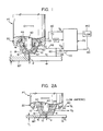
- FIGURE 1 shows a plasma arc cutting torch PT for cutting a workpiece WP as the torch moves in the direction indicated by the arrow.
- the workpiece is conductive and has a thickness T.
- the plasma P issuing from the torch is used for the cutting process.
- the current applied to the torch by power supply PS is adjusted to a set point current which is roughly determined by the mathematical relationship that the arc current in amperes divided by 100 is the thickness T for optimum cutting. This relationship is illustrative and is not intended to be a limitation to the invention.
- torch PT includes an electrically conductive nozzle 10 having a lower outlet 12 through which plasma arc P issues for cutting workpiece WP.
- the nozzle is formed from a metal, such as copper, and includes a generally cylindrical inner chamber 14 terminating in a lower generally semi-spherical end 16 at outlet 12.
- the outer surface 18 of the nozzle coacts with surface 22 of an insulated housing 20 to define a torch coolant gas passage 30. Showing of this feature is for illustrative purposes only and does not form a part of the present invention.
- an elongated electrode 40 which is often water cooled, terminating in a lower spherical end 42 generally matching the semi-spherical end 16 of chamber 14.
- the spherical end 42 of electrode 40 is provided with an appropriate high melting point insert.
- the outer surface 44 of electrode 40 coacts with the inner surface of chamber 14 to define a plasma gas passage 50 through which a gas flows, normally in a vortex. This gas is ionized into a plasma that passes through outlet 12.
- power supply PS applies a voltage across electrode 40 and nozzle 10, both of which are conductive metal, an arc is created in gas passage 50 to ionize the gas which arc is plasma P that cuts workpiece WP.
- Power supply PS in accordance with the preferred embodiment, is a solid state inverter with a standard phase controlled input rectifier for directing rectified three phase line current to the input of the inverter.
- the phase controlled rectifier can be adjusted to set the current available from power supply PS.
- the output current of the inverter is used to sustain an arc plasma between electrode 40 and workpiece WP during normal operation of torch PT.
- the voltage across lines 60, 62 is voltage between the electrode and nozzle. In practice, the voltage V A at line 60 is in the range of -80 to -150 volts D.C. Voltage V B at line 62 is applied to nozzle 10 and is in the general range of -60 to -120 volts D.C.
- a manually adjustable set point control 70 adjusts the input stage of power supply PS to set the desired arc current allowed to flow from the electrode to the workpiece during the cutting operation of torch PT.
- set point control 70 phases back the input rectifier to approximately 40 amperes of arc current flow between the electrode and workpiece or nozzle.
- set point control 70 is adjusted to a high current mode of operation, such as setting of the arc current to a value above about 50 amperes and preferably above 75-100 amperes.
- set point adjustment for the power supply has a lower mode with current of approximately 40 amperes and an upper adjustable set point level with a higher current determined by manual control 70.
- a resistor, or resistor network 80 connects line 62 to workpiece WP, which is normally grounded.
- the resistor or resistor network is shown in more detail in FIGURES 4 and 5.
- voltage V A is the potential at electrode 40
- voltage V B is the potential of nozzle 10
- voltage V c is the potential of workpiece WP.
- set point device or control 70 selects the set point. This set point can be at a low minimum current of 40 amperes or at a higher current mode, such as an arc current at above 75-100 amperes.
- plasma torch PT is operated in accordance with standard cutting practice.
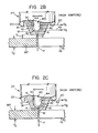
- FIGURES 2A-2D operating procedures for plasma torch PT are schematically illustrated.
- torch PT is operated at the lower minimum current level of 40 amperes to cut workpiece WP having a relatively small thickness T i . Since the current is relatively low the arc energy is low and the arc K bridges the gap through outlet 12 and between the electrode and the workpiece with plasma P. Consequently, the arc K remains in the plasma and heats the workpiece.
- the nozzle can be in contact with workpiece WP and can be dragged along the workpiece without substantial harm to the electrode. If arc K attaches to the nozzle, it does not have sufficient energy to damage or cut the metal of the nozzle.
- nozzle 10 When the thickness of the workpiece WP is increased to a substantial value T 2 , as shown in FIGURE 2B, nozzle 10 must be held at a spacing from workpiece WP during the cutting operation. Since spacing S, which is normally in the general range of 0.100-0.125 inches, arc K passes through outlet 12 in the plasma. When high current of a high operating mode is provided by power supply PS the spacing prevents the arc from attaching to the nozzle. This higher arc current is required to provide more energy to create a sufficient energy in plasma P for cutting the thicker workpiece. Spacing S and the thickness of the workpiece demands that the plasma column P extends at a sustained energy level for a substantial distance from outlet 12.
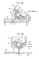
- the cutting operation for the thicker plate is optimized and the high current value is set above the minimum or low mode. So long as the nozzle does not contact the workpiece while the high current mode is used, the nozzle has substantial life. This life is drastically reduced if torch PT engages workpiece WP as is shown schematically in FIGURE 2C. Spacing S is zero. When this occurs, arc K tends to attach to the nozzle at the walls of outlet 12. This arcing condition causes substantial damage to the nozzle. Thus, high current operation for cutting, as illustrated in FIGURE 2C, will cause drastic and rapid deterioration of the torch by destroying the end of nozzle 10 if the operator allows the nozzle to contact the workpiece being cut.
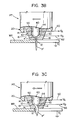
- FIGURES 3A-3C Deterioration of the nozzle is schematically illustrated in FIGURES 3A-3C wherein normal high current operation is shown in FIGURE 3A.
- plasma P is driven by a high current and arc K is maintained in the plasma column P.
- arc K is transferred into a somewhat non-descript arc K' which extends through outlet 12 to workpiece WP and tends to attach to the nozzle.
- This arc action produces a modified, dispersed plasma P' having an enlarged cross section and less energy per cross sectional area. This arc action reduces cutting efficiency and causes drastic and rapid erosion of the outlet 12 by enlarging the size of the outlet, as shown in FIGURE 3C.
- Arc K' attaches to the nozzle and rapidly erodes portions if not all of the inner wall of outlet 12. This enlarges the outlet 12 to produce a large diameter plasma P' shown schematically in dotted lines. The optimum shape of plasma P is shown in solid lines. This shape results in cutting efficiency. Thus, the torch is rapidly rendered ineffective when contact is made between the nozzle and the workpiece as the torch PT is cutting in the high current mode of operation.
- the present invention provides a circuit for protecting the nozzle.
- the inventive protective circuit includes means for sensing the voltage of the nozzle, means for comparing the nozzle voltage with a reference voltage and means for limiting the arc current to the torch, i.e. holding the current to a low level and/or setting a low level maximum obtainable current, when the nozzle voltage is within a selected range of the reference voltage.
- the high current mode is allowed to continue when the operator raises the torch to remove the detected contact.
- the reference voltage is voltage V c which voltage is the grounded workpiece voltage.
- the selected range or voltage amount is less than 5.0 volts.
- the voltage between these two metal components generally equalizes so that the nozzle voltage is at the reference voltage.
- This condition is sensed and the arc current is shifted at power supply PS to the low current level, which in practice is 40 amperes.
- the low level or low current mode of operation may be at any desired low, non destructive operating current, such as a low current in the range of 35-50 amperes.
- the particular value of the low current level of torch PT is not a broad aspect of the present invention.
- the protective circuit is used in a system and method for protecting torch PT by detecting the voltage of the nozzle and, upon such detection, shifting power supply PS to a lower mode of current operation. Workpiece contact is also a sensed condition when the nozzle contacts any grounded metal.
- torch PT shifts to a low current mode of operation. When the contact is broken, normally by the operator, the torch shifts back into its normal current set point, which current may be substantially above the minimum current level of the low current operating mode. When the operating current level is noticeably decreased, the operator is alerted to a surface contact. The torch is merely lifted from the workpiece and the cutting operation is continued without any hesitation for restarting. This is a substantial advance in the art of plasma arc cutting.
- resistor or resistor network 80 is a voltage divider with resistor sections 82, 84.
- a "CONTACT" sensing line 110 is connected to read the voltage between the resistor sections. The voltage on sensing line 110 is shifted toward voltage V c when nozzle 10 contacts workpiece WP. Grounding of line 62 places a logic 0 on line 110. This voltage actuates a drag or contact sensing circuit 112.
- a logic 0 from circuit 112 appears in output 114 and is communicated with microprocessor of power supply PS where the logic can be inverted, as indicated schematically by inverter 116 in FIGURE 4.
- the "CONTACT" signal is interrogated by a contact identifying subroutine schematically illustrated as "Current Limit” block 130. If nozzle contact is identified by subroutine 130, a signal indicated as line 132 is outputted from the microprocessor to a phased back control 140 of the input rectifier of power supply PS.
- Phase back control 140 can set the output of the power supply to a low current level, i.e. 40 amperes, or it can set a maximum current level at the 40 amperes.
- nozzle contact has no effect on the operation of power supply PS and the cutting operation continues in normal fashion even if the nozzle is in contact with the workpiece, as shown in FIGURE 2A.
- AND gate 150 is shown as having inputs 152, 154 and 156 with an output 158.
- Nozzle contact places a yes or logic 1 condition on line 152.
- a lack of a low current mode makes input line 154 a logic 1.
- the existence of a high current mode applies a logic 1 to input 156.
- output 158 is energized. This shifts or actuates low current mode circuit 160 to give a logic 1 in line 132. If the nozzle contact appears during a low current mode of operation then a logic 0 appears on input 154 of gate 150.
- This operation of the invention represents a slightly modified concept of the invention than the concept previously described.
- a maximum low current is set whenever there is contact or an actual low current is set for the power supply. When there is no contact, the maximum current or low current is released and set point device 70 controls the operation of power supply PS.
- FIGURE 4A A slight modification of the system in FIGURE 4 is shown in FIGURE 4A, where there is no signal in line 132 if the nozzle contacts the workpiece when the torch is already in the low current mode of operation. Whenever there is nozzle contact with the torch in the high current mode, there is a signal in line 132.
- FIGURE 4A is merely a schematic logic diagram to show another logic arrangement that could be used for practicing the present invention.
- the invention is detecting the touching of the nozzle to a grounded metal such as the workpiece and, then, limiting the arc current to a low level while contact exists during the cutting operation.
- This novel arrangement does not turn off the torch, or disrupt the cutting operation. The operator upon noticing a shift to a low current merely lifts the torch and continues cutting.
- FIGURE 5 reveals the detail circuit 112 for sensing contact of the nozzle and workpiece.
- cascaded transistors 200, 222 are conductive when line 110 is grounded to give a contact signal.
- Base 202 of transistor 200 is then grounded to actuate circuit 112.
- Transistor 220 is conductive and LED 230 is activated.
- Optical coupled output 240 is then energized to produce a drag or contact signal in line 114 as schematically illustrated in FIGURE 4. In this manner, a signal appears in line 114 when the voltage V B is within 5.0 volts of voltage V c or ground potential.
- the arc can attach to the nozzle or pass through the outlet without rapid damage to the nozzle.
- the current is high the nozzle must remain spaced from the workpiece so the arc will pass directly through the outlet to the workpiece.
- this high current operation will damage the nozzle by attaching to the nozzle while forming the low resistance or impedance path for the arc.
Landscapes
- Engineering & Computer Science (AREA)
- Physics & Mathematics (AREA)
- Plasma & Fusion (AREA)
- Spectroscopy & Molecular Physics (AREA)
- Mechanical Engineering (AREA)
- Arc Welding Control (AREA)
- Plasma Technology (AREA)
- Arc Welding In General (AREA)
Applications Claiming Priority (2)
| Application Number | Priority Date | Filing Date | Title |
|---|---|---|---|
| US07/684,331 US5183990A (en) | 1991-04-12 | 1991-04-12 | Method and circuit for protecting plasma nozzle |
| US684331 | 1991-04-12 |
Publications (2)
| Publication Number | Publication Date |
|---|---|
| EP0508481A2 true EP0508481A2 (de) | 1992-10-14 |
| EP0508481A3 EP0508481A3 (en) | 1992-11-19 |
Family
ID=24747627
Family Applications (1)
| Application Number | Title | Priority Date | Filing Date |
|---|---|---|---|
| EP19920106308 Withdrawn EP0508481A3 (en) | 1991-04-12 | 1992-04-11 | Method and circuit for protecting plasma nozzle |
Country Status (6)
| Country | Link |
|---|---|
| US (1) | US5183990A (de) |
| EP (1) | EP0508481A3 (de) |
| JP (1) | JPH0822464B2 (de) |
| KR (1) | KR950011708B1 (de) |
| AU (1) | AU632012B2 (de) |
| TW (1) | TW210970B (de) |
Cited By (3)
| Publication number | Priority date | Publication date | Assignee | Title |
|---|---|---|---|---|
| US5717187A (en) * | 1994-03-25 | 1998-02-10 | Commonwealth Scientific And Industrial Research Organisation | Plasma torch condition monitoring |
| US5756960A (en) * | 1994-03-25 | 1998-05-26 | Commonwealth Scientific And Industrial Research Organization | Detecting non-symmetrical nozzle wear in a plasma arc torch |
| EP1601238A3 (de) * | 2004-05-24 | 2009-03-04 | Koike Sanso Kogyo Co., Ltd. | Vorrichtung zur Erfassung der Lebensdauer eines Plasmabrenners |
Families Citing this family (31)
| Publication number | Priority date | Publication date | Assignee | Title |
|---|---|---|---|---|
| JP3417508B2 (ja) * | 1995-07-12 | 2003-06-16 | 株式会社小松製作所 | プラズマトーチ |
| US5844197A (en) * | 1997-07-28 | 1998-12-01 | The Lincoln Electric Company | Arc retract circuit and method |
| US5990443A (en) * | 1998-03-12 | 1999-11-23 | Thermal Dynamics Corporation | Plasma torch pilot arc circuit |
| US6153850A (en) | 1999-04-29 | 2000-11-28 | The Esab Group, Inc. | Method of cutting a workpiece along an arcuate path with a plasma arc torch |
| US6540586B2 (en) * | 1999-08-25 | 2003-04-01 | Flow International Corporation | Apparatus and methods for collision detection and recovery for waterjet cutting systems |
| US6379214B1 (en) | 1999-08-25 | 2002-04-30 | Flow International Corporation | Apparatus and methods for z-axis control and collision detection and recovery for waterjet cutting systems |
| JP2004237321A (ja) * | 2003-02-06 | 2004-08-26 | Komatsu Sanki Kk | プラズマ加工装置 |
| US7087856B2 (en) * | 2004-11-03 | 2006-08-08 | The Esab Group, Inc. | System and method for determining an operational condition of a torch |
| US20080164243A1 (en) * | 2005-02-15 | 2008-07-10 | Mitoshi Chigira | Gas Nozzle for Arc Welding |
| US8258424B2 (en) | 2009-08-20 | 2012-09-04 | The Esab Group, Inc. | Plasma torch with electrode wear detection system |
| US9111729B2 (en) * | 2009-12-03 | 2015-08-18 | Lam Research Corporation | Small plasma chamber systems and methods |
| US9190289B2 (en) * | 2010-02-26 | 2015-11-17 | Lam Research Corporation | System, method and apparatus for plasma etch having independent control of ion generation and dissociation of process gas |
| JP5645157B2 (ja) * | 2010-06-03 | 2014-12-24 | 国立大学法人東京工業大学 | プラズマ装置 |
| US10039178B2 (en) * | 2010-07-16 | 2018-07-31 | Hypertherm, Inc. | Failure event detection in a plasma arc torch |
| US9967965B2 (en) | 2010-08-06 | 2018-05-08 | Lam Research Corporation | Distributed, concentric multi-zone plasma source systems, methods and apparatus |
| US8999104B2 (en) | 2010-08-06 | 2015-04-07 | Lam Research Corporation | Systems, methods and apparatus for separate plasma source control |
| US9449793B2 (en) | 2010-08-06 | 2016-09-20 | Lam Research Corporation | Systems, methods and apparatus for choked flow element extraction |
| US9155181B2 (en) | 2010-08-06 | 2015-10-06 | Lam Research Corporation | Distributed multi-zone plasma source systems, methods and apparatus |
| US9177762B2 (en) | 2011-11-16 | 2015-11-03 | Lam Research Corporation | System, method and apparatus of a wedge-shaped parallel plate plasma reactor for substrate processing |
| US10283325B2 (en) | 2012-10-10 | 2019-05-07 | Lam Research Corporation | Distributed multi-zone plasma source systems, methods and apparatus |
| US8872525B2 (en) | 2011-11-21 | 2014-10-28 | Lam Research Corporation | System, method and apparatus for detecting DC bias in a plasma processing chamber |
| US9083182B2 (en) | 2011-11-21 | 2015-07-14 | Lam Research Corporation | Bypass capacitors for high voltage bias power in the mid frequency RF range |
| US9508530B2 (en) | 2011-11-21 | 2016-11-29 | Lam Research Corporation | Plasma processing chamber with flexible symmetric RF return strap |
| US9263240B2 (en) | 2011-11-22 | 2016-02-16 | Lam Research Corporation | Dual zone temperature control of upper electrodes |
| US8898889B2 (en) | 2011-11-22 | 2014-12-02 | Lam Research Corporation | Chuck assembly for plasma processing |
| US9396908B2 (en) | 2011-11-22 | 2016-07-19 | Lam Research Corporation | Systems and methods for controlling a plasma edge region |
| US10586686B2 (en) | 2011-11-22 | 2020-03-10 | Law Research Corporation | Peripheral RF feed and symmetric RF return for symmetric RF delivery |
| KR20170000973U (ko) * | 2015-09-04 | 2017-03-15 | 현대중공업 주식회사 | 플라즈마 가공장치 |
| DE102016125599A1 (de) * | 2016-12-23 | 2018-06-28 | Newfrey Llc | Verfahren und Vorrichtung zum Fügen von Fügeelementen auf Bauteile |
| CA3191050A1 (en) * | 2020-08-28 | 2022-03-03 | Nikolay Suslov | Systems, methods, and devices for generating predominantly radially expanded plasma flow |
| EP4008471A1 (de) * | 2020-12-02 | 2022-06-08 | Fronius International GmbH | Verfahren und schweissvorrichtung mit detektion von elektrischen kontakten bei einem schweissprozess |
Family Cites Families (16)
| Publication number | Priority date | Publication date | Assignee | Title |
|---|---|---|---|---|
| DE1615352B2 (de) * | 1967-11-02 | 1971-09-02 | VEB Mansfeld Kombinat Wilhelm Pieck, χ 4250 Lutherstadt Eisleben | Schaltungsanordnung und vorrichtung fuer plasma handbrenner |
| US3809850A (en) * | 1972-05-17 | 1974-05-07 | Union Carbide Corp | Plasma arc power system for welding |
| US4156125A (en) * | 1977-02-28 | 1979-05-22 | Caterpillar Tractor Co. | Method of and means for spacing control of plasma arc cutting torch including vector velocity compensation |
| US4330700A (en) * | 1980-03-25 | 1982-05-18 | Peter Jagieniak | Plasmaburner with contact protection |
| US4585921A (en) * | 1983-07-20 | 1986-04-29 | Thermal Dynamics Corporation | Torch operation interlock device |
| JPS6163366A (ja) * | 1984-09-03 | 1986-04-01 | Hitachi Seiko Ltd | プラズマ切断装置 |
| JPS61266179A (ja) * | 1985-05-22 | 1986-11-25 | Tokushu Denkyoku Kk | 移行型プラズマアーク溶接装置におけるプラズマアーク電圧の自動制御装置 |
| IT1191365B (it) * | 1986-06-26 | 1988-03-16 | Cebora Spa | Circuito di comando per una apparecchiatura di talgio o saldatura al plasma ad arco trasferito |
| EP0436021B1 (de) * | 1988-03-24 | 1996-09-25 | Kabushiki Kaisha Komatsu Seisakusho | Plasmabogen-schneidevorrichtung und deren regelung |
| US4839499A (en) * | 1988-06-13 | 1989-06-13 | Cyclomatic Industries, Inc. | System for supplying power to different cutting torches |
| IT1225341B (it) * | 1988-11-15 | 1990-11-13 | Cebora Spa | Circuito di protezione per una apparecchiatura di saldatura o taglio al plasma con arco non trasferito o trasferito |
| US4929811A (en) * | 1988-12-05 | 1990-05-29 | The Lincoln Electric Company | Plasma arc torch interlock with disabling control arrangement system |
| JPH02172629A (ja) * | 1988-12-26 | 1990-07-04 | Mitsubishi Electric Corp | 加工装置 |
| JPH03479A (ja) * | 1989-05-25 | 1991-01-07 | Hitachi Ltd | プラズマ溶接装置及び溶接方法 |
| JPH07102466B2 (ja) * | 1989-06-20 | 1995-11-08 | 松下電器産業株式会社 | プラズマ切断機 |
| CA2082812A1 (en) * | 1990-05-15 | 1991-11-16 | Peter Vierboom | A dc switched arc torch power supply |
-
1991
- 1991-04-12 US US07/684,331 patent/US5183990A/en not_active Expired - Lifetime
-
1992
- 1992-04-09 AU AU14794/92A patent/AU632012B2/en not_active Ceased
- 1992-04-11 EP EP19920106308 patent/EP0508481A3/en not_active Withdrawn
- 1992-04-13 KR KR1019920006084A patent/KR950011708B1/ko not_active Expired - Fee Related
- 1992-04-13 JP JP4135514A patent/JPH0822464B2/ja not_active Expired - Lifetime
- 1992-04-13 TW TW081102861A patent/TW210970B/zh active
Cited By (3)
| Publication number | Priority date | Publication date | Assignee | Title |
|---|---|---|---|---|
| US5717187A (en) * | 1994-03-25 | 1998-02-10 | Commonwealth Scientific And Industrial Research Organisation | Plasma torch condition monitoring |
| US5756960A (en) * | 1994-03-25 | 1998-05-26 | Commonwealth Scientific And Industrial Research Organization | Detecting non-symmetrical nozzle wear in a plasma arc torch |
| EP1601238A3 (de) * | 2004-05-24 | 2009-03-04 | Koike Sanso Kogyo Co., Ltd. | Vorrichtung zur Erfassung der Lebensdauer eines Plasmabrenners |
Also Published As
| Publication number | Publication date |
|---|---|
| AU632012B2 (en) | 1992-12-10 |
| TW210970B (de) | 1993-08-11 |
| KR950011708B1 (ko) | 1995-10-07 |
| EP0508481A3 (en) | 1992-11-19 |
| JPH0822464B2 (ja) | 1996-03-06 |
| KR920020997A (ko) | 1992-11-21 |
| JPH05261554A (ja) | 1993-10-12 |
| US5183990A (en) | 1993-02-02 |
| AU1479492A (en) | 1992-10-29 |
Similar Documents
| Publication | Publication Date | Title |
|---|---|---|
| US5183990A (en) | Method and circuit for protecting plasma nozzle | |
| US5866869A (en) | Plasma pilot arc control | |
| US5506384A (en) | Plasma arc cutting machine with variable constant current source and variable resistor | |
| AU614449B2 (en) | Plasma arc torch system interlock | |
| US4748312A (en) | Plasma-arc torch with gas cooled blow-out electrode | |
| US5951888A (en) | Plasma electrode with arc-starting grooves | |
| JP4266206B2 (ja) | プラズマトーチの寿命検出装置 | |
| GB2295569B (en) | Enhanced laser beam welding | |
| US5530220A (en) | Plasma torch arc transfer circuit | |
| US4581516A (en) | Plasma torch with a common gas source for the plasma and for the secondary gas flows | |
| US4585921A (en) | Torch operation interlock device | |
| US6933463B2 (en) | Main arc ignition device and main arc ignition control method of plasma cutting machine | |
| US3174027A (en) | Pilot arc starting-arc working systems | |
| US5695663A (en) | Plasma cutting method and NC plasma cutting apparatus | |
| US3778579A (en) | Arc control | |
| EP0213689A2 (de) | Abschaltschaltung für Plasmabrenner | |
| US6566625B1 (en) | Welding apparatus and method | |
| US3354289A (en) | Method of increasing the durability of nozzles for arc-plasma-torches with high power density and a connection arrangement for carrying out the process | |
| JP2850397B2 (ja) | プラズマアーク加工装置 | |
| JP2002110399A (ja) | トーチ間移行プラズマ装置 | |
| RU2811984C1 (ru) | Быстроизнашивающаяся деталь для дуговой горелки, плазменной горелки или плазменной резательной горелки, а также дуговая горелка, плазменная горелка или плазменная резательная горелка с указанной деталью и способ плазменной резки, а также способ изготовления электрода для дуговой горелки, плазменной горелки или плазменной резательной горелки | |
| JP3472625B2 (ja) | プラズマトーチの保護装置 | |
| JPH0337834B2 (de) | ||
| JP3264741B2 (ja) | フィラワイヤ供給tig溶接装置 | |
| JPH05300642A (ja) | 回路電流の限流遮断方法 |
Legal Events
| Date | Code | Title | Description |
|---|---|---|---|
| PUAI | Public reference made under article 153(3) epc to a published international application that has entered the european phase |
Free format text: ORIGINAL CODE: 0009012 |
|
| PUAL | Search report despatched |
Free format text: ORIGINAL CODE: 0009013 |
|
| AK | Designated contracting states |
Kind code of ref document: A2 Designated state(s): AT BE CH DE DK ES FR GB GR IT LI LU MC NL PT SE |
|
| AK | Designated contracting states |
Kind code of ref document: A3 Designated state(s): AT BE CH DE DK ES FR GB GR IT LI LU MC NL PT SE |
|
| 17P | Request for examination filed |
Effective date: 19921128 |
|
| 17Q | First examination report despatched |
Effective date: 19950202 |
|
| STAA | Information on the status of an ep patent application or granted ep patent |
Free format text: STATUS: THE APPLICATION IS DEEMED TO BE WITHDRAWN |
|
| 18D | Application deemed to be withdrawn |
Effective date: 19950613 |