EP0508396B1 - Tamper-indicating plastic closure - Google Patents
Tamper-indicating plastic closure Download PDFInfo
- Publication number
- EP0508396B1 EP0508396B1 EP92106060A EP92106060A EP0508396B1 EP 0508396 B1 EP0508396 B1 EP 0508396B1 EP 92106060 A EP92106060 A EP 92106060A EP 92106060 A EP92106060 A EP 92106060A EP 0508396 B1 EP0508396 B1 EP 0508396B1
- Authority
- EP
- European Patent Office
- Prior art keywords
- closure
- tamper
- tab
- flexible
- pad
- Prior art date
- Legal status (The legal status is an assumption and is not a legal conclusion. Google has not performed a legal analysis and makes no representation as to the accuracy of the status listed.)
- Expired - Lifetime
Links
Images

Classifications
-
- B—PERFORMING OPERATIONS; TRANSPORTING
- B65—CONVEYING; PACKING; STORING; HANDLING THIN OR FILAMENTARY MATERIAL
- B65D—CONTAINERS FOR STORAGE OR TRANSPORT OF ARTICLES OR MATERIALS, e.g. BAGS, BARRELS, BOTTLES, BOXES, CANS, CARTONS, CRATES, DRUMS, JARS, TANKS, HOPPERS, FORWARDING CONTAINERS; ACCESSORIES, CLOSURES, OR FITTINGS THEREFOR; PACKAGING ELEMENTS; PACKAGES
- B65D41/00—Caps, e.g. crown caps or crown seals, i.e. members having parts arranged for engagement with the external periphery of a neck or wall defining a pouring opening or discharge aperture; Protective cap-like covers for closure members, e.g. decorative covers of metal foil or paper
- B65D41/32—Caps or cap-like covers with lines of weakness, tearing-strips, tags, or like opening or removal devices, e.g. to facilitate formation of pouring openings
- B65D41/34—Threaded or like caps or cap-like covers provided with tamper elements formed in, or attached to, the closure skirt
- B65D41/3423—Threaded or like caps or cap-like covers provided with tamper elements formed in, or attached to, the closure skirt with flexible tabs, or elements rotated from a non-engaging to an engaging position, formed on the tamper element or in the closure skirt
- B65D41/3428—Threaded or like caps or cap-like covers provided with tamper elements formed in, or attached to, the closure skirt with flexible tabs, or elements rotated from a non-engaging to an engaging position, formed on the tamper element or in the closure skirt the tamper element being integrally connected to the closure by means of bridges
Definitions
- the present invention relates generally to tamper-indicating closures for containers, and more particularly to a tamper-evident plastic closure including a pilfer band configured for enhanced flexibility having container-engaging projections to facilitate application of the closure to a container with high-speed application equipment.
- EP-A-0381118 U.S.-A-4,938,370, to McBride
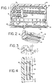
- FIG. 1 illustrates a tamper-indicating plastic closure construction for use in connection with a bottle or like container having a threaded neck.
- the closure disclosed in this patent is particularly desirable in that two different modes of tamper-indication are provided, thus enhancing its tamper-resistance.
- the closure of this patent includes an annular pilfer band which is at least partially detachably joined to the bottom of a cylindrical skirt portion of an upper closure cap.
- the pilfer band includes a plurality of circumferentially spaced, relatively flexible tab elements which extend inwardly of the pilfer band for coaction with an annular locking ring on an associated container.
- the flexible tabs are urged upwardly.
- the tabs assume a more inwardly extending disposition, for coaction with the container locking ring so that the pilfer band is detached from the skirt portion during closure removal.
- the pilfer band includes an annular interference bead positioned generally beneath the flexible tabs. In the event that the pilfer band does not initially detach from the closure skirt portion, by virtue of the tabs interacting with the container in their initial upwardly and inwardly extending disposition, the tabs can further function to cooperate with the interference bead.
- the upward flexing movement of the flexible tabs during closure application creates stresses on the closure, including stress on the frangible connection which detachably connects the pilfer band to the closure skirt portion.
- the stresses exerted on the frangible connection can be relatively high. This poses somewhat of a dilemma, in that the frangible connection must be configured to consistently and easily fracture and break attendant to closure removal, while at the same time be sufficiently strong to resist premature breakage during high-speed application.
- the present invention contemplates an improved construction for a tamper-indicating closure of the above type, which construction facilitates high-speed closure application without compromise of the reliable performance of the closure.
- the tamper-indicating plastic closure of the present invention facilitates high-speed closure application by reducing the stresses to which the closure is subjected during application. This is achieved by configuring the flexible tab elements of the closure pilfer band for enhanced flexibility, while at the same time assuring operability in the two different modes of tamper-indication.
- the flexible tabs are configured for enhanced flexibility by including a base portion of relatively reduced thickness for enhanced flexibility, as well as a locally thickened portion for the desired coaction with an interference bead of the pilfer band.
- the present tamper-indicating plastic closure is configured for use with a container having an annular locking ring.
- the closure comprises a plastic cap including a top wall portion, and an annular depending cylindrical skirt portion.
- a helical thread formation is provided on the inside surface of the skirt portion for coaction with a like thread formation on the exterior finish of the associated container.
- the closure further includes an annular pilfer band at least partially detachably connected to and depending from the skirt portion of the closure.
- the pilfer band includes an annular band portion, and a plurality of circumferentially spaced inwardly extending flexible tabs. Each flexible tab has a free end portion which is engageable with the container locking ring when the flexible tabs extend upwardly and inwardly during removal of the closure from the container.
- the pilfer band further includes an inwardly extending annular interference bead positioned beneath and adjacent to the flexible tabs.
- a second means or mode of tamper-indication is provided by disposition of the flexible tabs in a generally downwardly, inwardly extending orientation, between the container locking ring and the interference bead of the pilfer band.
- the flexible tabs are configured for enhanced flexibility, thereby facilitating high-speed application to containers with relatively reduced stressing of the closure.
- These tabs include a relatively thick central portion, and a base portion having a relatively reduced thickness to enhance the flexibility of the tab.
- each of the relatively thick central portions is positionable between the associated container locking ring and the interference bead of the pilfer band.
- each of the flexible tabs has a generally planar configuration, with the relatively thick central portion comprising a discrete, elongated pad or node on a lower surface of the planar portion of the tab.
- a preferred frangible connection for at least partially detachably connecting the pilfer band to the closure skirt comprises a plurality of circumferentially spaced, frangible ribs or bridges which extend between the inside surfaces of the skirt portion and the annular band portion of the pilfer band.
- the pilfer band is otherwise separated and distinguished from the skirt portion by a circumferentially extending score line which extends at least partially around the closure. The score line extends partially into the frangible ribs, thereby defining a fracturable "residual" portion for each rib.
- each of the flexible tabs configured for enhanced flexibility includes a base portion of relatively reduced thickness.
- each of these flexible tabs also includes a free end portion of relatively reduced thickness, which is preferably of substantially equal thickness to the base portion.
- the plastic closure 10 includes an upper plastic closure cap or shell 12, preferably formed from polypropylene, which includes a circular top wall portion 14, and a depending, annular cylindrical skirt portion 16.
- the skirt portion 16 includes an internal, helical thread formation 18 for mating with a like thread formation on the exterior finish of an associated container.
- the illustrated embodiment of the closure 10 is particularly configured for use with containers for carbonated beverages, and to this end, a plurality of axially extending vent grooves 20 are provided in the skirt portion 16, generally traversing the thread formation 18. Additionally, the closure may include a sealing liner 22 adjacent the top wall portion 14, which is configured for sealing engagement with the associated container.
- the closure includes an annular pilfer band 24 depending from the lower edge of skirt portion 16.
- the pilfer band 24 is at least partially detachably connected to the skirt portion 16, with the pilfer band being configured for cooperative interaction with an locking ring L (FIGURES 5 and 6) of an associated container for at least partially detaching and separating the pilfer band from the closure skirt portion.
- the pilfer band 24 includes an annular band portion 26.
- the desired frangible connection between the pilfer band and the closure skirt portion is preferably provided by a plurality of circumferentially spaced, frangible rib-like bridges 28 which extend between the inside surfaces of the skirt portion 16 and the band portion 26 of the pilfer band.
- the pilfer band is otherwise separated and distinguished from the skirt portion of the closure cap 12 by a circumferential score line 30 which extends through the side wall of the closure construction, and partially into the frangible ribs 28.
- each of the frangible ribs 28 defines an unscored "residual" portion, which residual portions collectively provide a frangible connection between the pilfer band and the closure cap.
- the score line 30 can extend substantially completely about the circumference of the closure. In distinction, for some applications it is desirable to have the pilfer band remain attached to the closure cap, after partial separation of the closure therefrom.
- the band portion 26 of the pilfer band can be configured to break and split in one or more regions, attendant to failure of the frangible bridges 28, with the one or more pieces of the pilfer band thereafter remaining attached to the skirt portion of the closure by one or more areas exhibiting relatively greater strength than the bridges 28.
- the pilfer band 24 of the plastic closure 10 is desirably configured to provide two modes or arrangements for interacting with the locking ring L of the associated container, thus effecting partial or complete separation of the pilfer band from the closure skirt portion by fracture of the bridges 28.
- the pilfer band 24 includes a plurality of circumferentially spaced, inwardly extending flexible tabs 32 which extend integrally inwardly of the band portion 26.
- the pilfer band includes an inwardly extending, annular interference bead 34 positioned generally beneath the flexible tabs 32.
- FIGURES 5 and 6 The two modes of tamper-indication are diagrammatically illustrated in FIGURES 5 and 6.
- the pilfer band 24 is positioned relative to the container locking ring L such that the flexible tabs 32 can assume a generally inwardly extending, upwardly angled disposition.
- the flexible tabs are preferably dimensioned so that they can flex to an out-of-the-way disposition (shown in phantom line in FIGURE 5) during application of the closure to the container.
- a second mode of operation is provided as illustrated diagrammatically in FIGURE 6.
- the tabs 32 are configured to coact with the annular interference bead 34, of the pilfer band 24. This coaction reduces the effective inside diameter of the pilfer band of the closure, and thereby effects the desired interfering engagement with the container locking ring L.
- FIGURE 6 illustrates the disposition of flexible tab 32 between the container locking ring and the annular interference bead 34 provides the second arrangement for at least partially detaching the pilfer band 24 from the skirt portion 16 by fracturing bridges 28.
- frangible bridges 28 it is very desirable that any premature failure or fracture of the frangible bridges 28 be avoided during application of the closure 10 to an associated container.
- frangible bridges reliably and consistently fail and fracture attendant to removal of the closure from the container.
- the collective strength of the frangible bridges 28 is carefully controlled by controlling the depth to which the circumferential score 30 is cut through the closure side wall and partially into the frangible bridges. Nevertheless, it has been found that enhanced reliability can be achieved by facilitating application of the closure to a container in a manner which avoids subjecting the frangible bridges to excessive stress.
- each of the flexible tabs 32 are configured in accordance with the present invention for enhanced flexibility.
- each of the flexible tabs has a generally planar configuration, including a planar portion 36.
- at least some of the flexible tabs, and preferably all of them, include a locally thickened or enlarged region defined by a generally elongated pad or node 38.
- the pad or node of each flexible tab is positioned on the generally downwardly facing lower surface of the tab, and thus acts to define a base portion, adjacent the band portion 26, having a relatively reduced thickness to enhance the flexibility of the tab.
- each of the tabs 32 having a pad 38 also includes a free end portion of relatively reduced thickness, compared to the central portion, with the base portion and free end portion of substantially equal thickness.
- the enhanced flexibility afforded by the base portion of reduced thickness facilitates the upward movement of the tabs during application of the closure to a container.
- the region of relatively greater thickness at the pad 38 still assures the desired cooperation with the interference bead 34 in the second mode of tamper-indication.
- the pad 38 of each flexible tab is engageable with the annular interference bead 34 when the tabs extend inwardly and downwardly, and are disposed between the interference bead and the container locking ring L.
- each tab defines a generally flat surface extending between arcuate edge portions.
- Typical dimensions for the flexible tabs 32 are illustrated in FIGURES 3 and 4. These dimensions are intended as illustrative of a current embodiment, but are not intended to limit the invention to these presently preferred dimensional characteristics.
- the planar portion 36 of each flexible tab 32 has a thickness dimension "t" on the order of about 0.0127 to 0.0508 cm (0.005 to 0.020 inches), with the base and free end portions having this thickness dimension.
- the thickness or height "h" of each of the pads 38 is on the order of about 0.0127 to 0.0508 cm (0.005 to 0.020 inches), for a total maximum tab thickness of 0.0254 to 0.1016 cm (0.010 to 0.040 inches).
- each pad 38 is preferably on the order of about 0.1016 cm to 0.1524 cm (0.040 to 0.060 inches), with the adjacent portions of each tab having radial dimensions "y" and "z” on the order of about 0.0127 to 0.0381 cm (0.005 to 0.015 inches), respectively.
- the pad 38 is generally radially centered on the respective tab.
- each flexible tab 32 is preferably on the order of about 0.51 to 1.02 cm (0.200 to 0.400 inches), with the pad 38 of each tab spaced inwardly from each of the side edges of the respective tab by a dimension "a" on the order of about 0.0127 to 0.038 cm (0.005 to 0.015 inches).
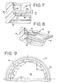
- FIGURES 7-10 therein is illustrated a modified embodiment of the present tamper-indicating plastic closure.
- the closure illustrated in these FIGURES is the same as the previously described embodiment.
- this embodiment includes a pilfer band 24, including an annular band portion 26, an annular interference bead 34, and a plurality of circumferentially spaced flexible tabs 32' which differ in some respects from the previously described flexible tabs 32.
- flexible tabs 32' each include a planar portion 36', preferably of a uniform thickness, and a locally thickened or enlarged region defined by a generally elongated pad or node 38'.
- the pad 38' of each flexible tab 32' is positioned on the generally downwardly facing lower surface of the tab, and thus acts to define a base portion, adjacent the band portion 26, having a relatively reduced thickness to enhance the flexibility of the tab.
- each of the tabs 32' having a pad 38' also includes a free end portion of relatively reduced thickness, compared to the central portion, with the base and free end portions of substantially equal thickness, corresponding to the thickness of planar portion 36'.
- the pad 38' is preferably configured to extend over a major portion of the lower surface of planar portion 36'.
- a current embodiment of the present closure includes 12 circumferentially spaced flexible tabs 32', with each tab having a circumferential or width dimension "f" on the order of 0.6 cm (0.236 inches), and a corresponding dimension "p" for pad 38' thereon of 0.55 cm (0.216 inches). Accordingly, the pad 38' is spaced inwardly from each side edge of the respective tab by about 0.0254 cm (0.010 inches).
- an inner edge portion of each of the flexible tabs 32' is generally arcuate, with these arcuate inner edges collectively defining a circle concentric with annular band 26 of the closure pilfer band.
- each pad 38' preferably has inner and outer edge portions which are generally concentric with the arcuate inner edge portion of the respective flexible tab.
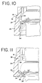
- the above-described current embodiment of the present closure is further configured such that the planar portion 36' of each flexible tab 32' has a thickness, as shown at dimension "b" of 0.0279 cm (0.011 inches), with the associated pad 38 having a thickness, shown at dimension "c", of about 0.0229 cm (0.009 inches).
- each pad 38 is generally perpendicular to the adjacent surface of the planar portion 36'.
- the inner edge portion of the pad 38' is spaced from the inner edge portion of the respective tab by a dimension "d", which in the illustrated embodiment is on the order of 0.01524 cm (0.006 inches).
- Each pad 38 also includes an outer edge portion 39', generally adjacent the base portion of the respective flexible tab, which is disposed at an acute angle " ⁇ " relative to the planar portion 36' of the tab on which the pad is positioned. In this current embodiment, angle " ⁇ " is on the order of 35'.
- the pads 38' of the flexible tabs 32' are engageable with the associated interference bead 34 for at least partially detaching the pilfer band 24 from the skirt portion of the closure by fracture of frangible bridges 28.
- fracture is achieved by positioning of the flexible tabs 32' between the container locking ring L and the interference bead 34 during removal of the closure from the associated container.
- the tabs 32' including the relatively thick portions at pads 38', cooperate with the interference bead 34 to increase the effective inside diameter of the pilfer band. By this action, sufficient interference is created with the container locking ring to effect fracture of the frangible bridges 28.
- Disposition of the pad 38' on the generally downwardly facing surface of the planar portion 36' of the associated pad 32' is believed to desirably enhance the interference force or "pull strength" which is created during closure removal, thereby acting to assure the intended fracture of the pilfer band for enhanced tamper-indication. This is believed to result from the cooperation of the flexible tabs 32' with the interference bead 34 such that substantial horizontal force components, rather than vertical force components, are created during interference with the container locking ring, as the pad 38' engages the interference bead.
- This engagement takes place at or near the angular outer edge 39' of the pad 38' and is believed to direct force components horizontally, which components are best resisted by the circumferential hoop strength of the annular band portion 26 of the pilfer band. Rather than subjecting the tabs 38' to stretching and deformation during closure removal, compressive forces are created which are directed in a manner in which the closure is best capable of resisting such forces without undesired deformation.
- each pad 32' with a base portion of relatively reduced thickness, which acts to assure high-speed application of the closure to a container without premature failure or fracture.
- the tab 32' By configuring the pad 38' to cover the major portion of the respective surface of planar portion 36', the tab 32' exhibits enhanced resistance to buckling and deformation, again with the desired flexibility achieved by virtue of the relatively reduced thickness at the base portion.
- the illustrated configuration is also believed to desirably enhance cooling during molding.
- the present closure be configured for two modes of tamper-indication, as respectively illustrated in FIGURES 10 and 11.
- flexible tabs 32' In a first mode of tamper-indication, flexible tabs 32' extend angularly upwardly and inwardly (as shown in phantom line in FIGURE 10) so that the inner edge or free end portions of the flexible tabs are positioned for interfering engagement with the container locking ring L.
- the flexible tabs 32' move to this inwardly angled disposition from a substantially upwardly extending disposition (shown in solid line in FIGURE 10) which vertical position the tabs assume as the closure is applied to the associated container.
- the resilience of the tabs causes them to move from this initial out-of-the-way disposition to the inwardly and upwardly extending disposition for the first mode of tamper-indication.
- the second mode of tamper-indication functions by decreasing the effective inside diameter of the pilfer band.
- the tabs 32' extend inwardly and downwardly, and are positionable between the container locking ring and the annular interference bead 34.
- the tabs 38' of each flexible tab 32' are engageable with the interference bead at or near the angular outer edge of each pad, with the illustrated configuration desirably acting to create horizontally directed compressive forces, attendant to closure removal, which are resisted by the hoop strength of the band portion 26 of the pilfer band. Fracture of frangible bridges 28 is thus effected.
- a pilfer band made in accordance with the present invention can be configured to function reliably in the second mode of tamper-indication, without reliance upon the first mode.
- tabs 32' can be configured to have a length "r" on the order of 0.256 cm (0.101 inches) if it is desired that the flexible tabs be configured for the above-described two modes of tamper-indication.
- the tabs can be relatively shortened, by providing them with a dimension "r" on the order of 0.218 cm (0.086 inches), if the tabs are to effect tamper-indication only in the downwardly, inwardly extending disposition of the tabs, by disposition between the container locking ring "r" and the annular interference bead 34.
- the tabs initially move downwardly during closure removal from their upwardly, inwardly dispositions without fracture of bridges 28.
- the bridges 28 then fracture with the tabs extending downwardly and inwardly.
- this versatility is believed to be achieved, at least in part, by configuring the pads 38 so that they are engageable with the annular interference bead, in accordance with the illustrated embodiments of the present invention.
Landscapes
- Engineering & Computer Science (AREA)
- Mechanical Engineering (AREA)
- Closures For Containers (AREA)
Applications Claiming Priority (4)
| Application Number | Priority Date | Filing Date | Title |
|---|---|---|---|
| US07/682,635 US5167335A (en) | 1991-04-09 | 1991-04-09 | Tamper-indicating plastic closure |
| US682635 | 1991-04-09 | ||
| US847544 | 1992-03-13 | ||
| US07/847,544 US5205426A (en) | 1991-04-09 | 1992-03-13 | Tamper-indicating plastic closure |
Publications (2)
| Publication Number | Publication Date |
|---|---|
| EP0508396A1 EP0508396A1 (en) | 1992-10-14 |
| EP0508396B1 true EP0508396B1 (en) | 1995-06-07 |
Family
ID=27102934
Family Applications (1)
| Application Number | Title | Priority Date | Filing Date |
|---|---|---|---|
| EP92106060A Expired - Lifetime EP0508396B1 (en) | 1991-04-09 | 1992-04-08 | Tamper-indicating plastic closure |
Country Status (18)
| Country | Link |
|---|---|
| US (1) | US5205426A (ja) |
| EP (1) | EP0508396B1 (ja) |
| JP (1) | JP3382964B2 (ja) |
| AU (1) | AU649118B2 (ja) |
| BR (1) | BR9201259A (ja) |
| CA (1) | CA2065606A1 (ja) |
| DE (1) | DE69202806T2 (ja) |
| DK (1) | DK0508396T3 (ja) |
| EG (1) | EG19477A (ja) |
| ES (1) | ES2075516T3 (ja) |
| FI (1) | FI108939B (ja) |
| IL (1) | IL101470A (ja) |
| MA (1) | MA22496A1 (ja) |
| MY (1) | MY108613A (ja) |
| NO (1) | NO921391L (ja) |
| NZ (1) | NZ242179A (ja) |
| TR (1) | TR25983A (ja) |
| TW (1) | TW202413B (ja) |
Families Citing this family (35)
| Publication number | Priority date | Publication date | Assignee | Title |
|---|---|---|---|---|
| JPH01165027U (ja) * | 1988-05-11 | 1989-11-17 | ||
| EG21314A (en) | 1992-07-16 | 2000-10-31 | Driutt Rodney Malcolm | Tamper evident closure |
| US5320234A (en) * | 1992-10-07 | 1994-06-14 | H-C Industries, Inc. | Tamper-indicating plastic closure with pilfer band having staggered scores |
| US5356019A (en) * | 1992-10-14 | 1994-10-18 | Crown Cork & Seal Company, Inc. | Tamper indicating plastic closure |
| JP3298057B2 (ja) * | 1994-05-17 | 2002-07-02 | 日本クラウンコルク株式会社 | 合成樹脂製容器蓋 |
| FR2723571B1 (fr) * | 1994-08-12 | 1996-10-11 | Astra Plastique | Capsule de bouchage a vis et a bande d'inviolabilite |
| US5501349A (en) * | 1994-10-27 | 1996-03-26 | H-C Industries, Inc. | Tamper-indicating plastic closure with selectively strengthened pilfer band |
| RU2176974C2 (ru) * | 1995-06-14 | 2001-12-20 | Бруно ЗАМБУЛ | Резьбовая крышка для герметичного закрытия емкости с резьбовой горловиной (варианты) |
| KR100222112B1 (ko) * | 1995-11-15 | 1999-10-01 | 시바자키 야스오 | 밀봉기구 및 용기 |
| US5819976A (en) * | 1996-11-15 | 1998-10-13 | Alcoa Closure Systems International | Closure having self-venting, sealed promotion compartment |
| US5806707A (en) * | 1996-11-15 | 1998-09-15 | Alcoa Closure Systems International, Inc. | Removable inner promotional compartment closure and promotional gaming system |
| LU90016B1 (fr) * | 1997-01-31 | 1997-06-13 | Lynes Holding Sa | Bouchon à bande d'inviolabilité |
| US5846471A (en) * | 1997-04-01 | 1998-12-08 | Kerr Group, Inc. | Method for manufacturing a tamper-evident closure |
| AUPO788597A0 (en) | 1997-07-14 | 1997-08-07 | Closures And Packaging Services Limited | Closure |
| US6371317B1 (en) | 1998-08-07 | 2002-04-16 | Kerr Group, Inc. | Tamper indicating closure with foldable tab |
| US7344039B2 (en) * | 1998-08-07 | 2008-03-18 | Berry Plastics Corporation | Tamper indicating band having foldable tabs including tab extensions, tamper indicating closure including such tamper indicating band, and tamper indicating closure including such tamper indicating band and container |
| US6123212A (en) * | 1999-08-27 | 2000-09-26 | Alcoa Closure Systems International | Plastic closure with rotation-inhibiting projections |
| US6382445B1 (en) | 2000-06-23 | 2002-05-07 | Alcoa Closure Systems International | Linerless closure with pressure seal holding feature |
| US6355201B1 (en) | 2000-09-07 | 2002-03-12 | Captive Plastics, Inc. | Tamper-indicating closure with resilient locking projections |
| US6557714B2 (en) | 2001-03-22 | 2003-05-06 | Alcoa Closure Systems International, Inc. | Tamper-evident package |
| DE60202533T2 (de) * | 2001-08-13 | 2005-06-02 | CROWN Packaging Technology, Inc, Alsip | Verschlusskappe |
| US20050011855A1 (en) * | 2002-04-11 | 2005-01-20 | Zapata Felipe Lopez | Tamper-proof cap for bottles |
| US20030192853A1 (en) * | 2002-04-11 | 2003-10-16 | Zapata Felipe Lopez | Device inserted in inviolable lid for bottles |
| US6736280B1 (en) * | 2002-12-19 | 2004-05-18 | Felipe Lopez Zapata | Tamper-proof cap for bottles |
| US20050252878A1 (en) * | 2004-05-03 | 2005-11-17 | Alcoa Closure Systems International | Tamper-evident package |
| US7575123B2 (en) * | 2005-01-19 | 2009-08-18 | Rieke Corporation | Tamper-evident locking band for a container closure |
| US20080173611A1 (en) * | 2007-01-18 | 2008-07-24 | Silgan Holdings Inc. | Tamper evident band with hook |
| US20090045158A1 (en) * | 2007-08-14 | 2009-02-19 | Alcoa Closure Systems International, Inc. | Threaded closure with internal ribs |
| WO2009154666A2 (en) | 2008-04-30 | 2009-12-23 | Closure Systems International, Inc. | Tamper-evident package with improved opening performance |
| US10407225B2 (en) | 2017-11-07 | 2019-09-10 | Closure Systems International Inc. | Closure and package that vents at high pressure |
| US11021302B2 (en) | 2019-04-18 | 2021-06-01 | Closure Systems International Inc. | Closure with rotation-inhibiting projection |
| IT202100001430A1 (it) * | 2021-01-26 | 2022-07-26 | Sacmi | Tappo per contenitore. |
| US11970319B2 (en) | 2022-05-10 | 2024-04-30 | Closure Systems International Inc. | Anti-rotational and removal closure |
| US11945625B2 (en) | 2022-06-24 | 2024-04-02 | Closure Systems International Inc. | Package with closure |
| US11801977B1 (en) | 2022-12-02 | 2023-10-31 | Closure Systems International Inc. | Package with one-piece closure |
Family Cites Families (18)
| Publication number | Priority date | Publication date | Assignee | Title |
|---|---|---|---|---|
| US33265A (en) * | 1861-09-10 | Improvement in guard-fingers for harvesters | ||
| US4402418A (en) * | 1981-11-27 | 1983-09-06 | Ethyl Products Company | Tamperproof closure |
| US4470513A (en) * | 1982-09-23 | 1984-09-11 | Ethyl Molded Products Company | Tamper-indicating closure |
| US4635808A (en) * | 1982-12-14 | 1987-01-13 | Maxcap, Inc. | Plastic cap |
| US4550844A (en) * | 1984-06-22 | 1985-11-05 | Owens-Illinois, Inc. | Tamper resistant closure with tear-off band |
| US4613052A (en) * | 1985-04-29 | 1986-09-23 | Owens-Illinois, Inc. | Tamper-indicating closure, container and combination thereof |
| GB8525351D0 (en) * | 1985-10-15 | 1985-11-20 | Johnsen Jorgensen Plastics Ltd | Tamper resistant closures |
| US4709824A (en) * | 1985-12-12 | 1987-12-01 | Tri-Tech Systems International Inc. | Tamper evident plastic caps with lower separable or breakaway portions and a method of forming them |
| US4759456A (en) * | 1986-10-31 | 1988-07-26 | Owens-Illinois Closure Inc. | Tamper-indicating package and plastic closure therefore |
| CH671205A5 (ja) * | 1987-02-26 | 1989-08-15 | Crown Cork Ag | |
| US4801030A (en) * | 1987-05-28 | 1989-01-31 | Owens-Illinois Closure Inc. | Tamper-indicating closure and package |
| US4848614A (en) * | 1987-11-13 | 1989-07-18 | General Kap Corporation | Tamper-evident plastic closure |
| DK174625B1 (da) * | 1989-01-30 | 2003-07-28 | Alcoa Closure Systems Int Inc | Garantilukke af plast |
| US4938370B1 (en) * | 1989-04-26 | 2000-10-17 | Hc Ind | Tamper-indicating plastic closure |
| US4978017A (en) * | 1989-04-26 | 1990-12-18 | H-C Industries, Inc. | Tamper-indicating plastic closure |
| DE3912137A1 (de) * | 1989-04-13 | 1990-10-18 | Berg Jacob Gmbh Co Kg | Aus kunststoff bestehende verschlusskappe fuer einen behaelter |
| US5090788A (en) * | 1989-07-27 | 1992-02-25 | Owens-Illinois Closure Inc. | Tamper indicating package |
| US5107998A (en) * | 1991-06-14 | 1992-04-28 | Bruno Zumbuhl | Tamper proof ring for threaded closures |
-
1992
- 1992-03-13 US US07/847,544 patent/US5205426A/en not_active Expired - Lifetime
- 1992-03-31 NZ NZ24217992A patent/NZ242179A/en not_active IP Right Cessation
- 1992-04-01 AU AU13960/92A patent/AU649118B2/en not_active Ceased
- 1992-04-02 IL IL10147092A patent/IL101470A/en not_active IP Right Cessation
- 1992-04-04 MY MYPI92000584A patent/MY108613A/en unknown
- 1992-04-07 MA MA22777A patent/MA22496A1/fr unknown
- 1992-04-07 EG EG18092A patent/EG19477A/xx active
- 1992-04-08 BR BR929201259A patent/BR9201259A/pt not_active Application Discontinuation
- 1992-04-08 DE DE69202806T patent/DE69202806T2/de not_active Expired - Fee Related
- 1992-04-08 CA CA002065606A patent/CA2065606A1/en not_active Abandoned
- 1992-04-08 EP EP92106060A patent/EP0508396B1/en not_active Expired - Lifetime
- 1992-04-08 NO NO92921391A patent/NO921391L/no unknown
- 1992-04-08 ES ES92106060T patent/ES2075516T3/es not_active Expired - Lifetime
- 1992-04-08 DK DK92106060.4T patent/DK0508396T3/da active
- 1992-04-08 FI FI921556A patent/FI108939B/fi not_active IP Right Cessation
- 1992-04-09 JP JP11681392A patent/JP3382964B2/ja not_active Expired - Fee Related
- 1992-04-09 TR TR92/0316A patent/TR25983A/xx unknown
- 1992-04-14 TW TW081102885A patent/TW202413B/zh not_active IP Right Cessation
Also Published As
| Publication number | Publication date |
|---|---|
| AU649118B2 (en) | 1994-05-12 |
| ES2075516T3 (es) | 1995-10-01 |
| NZ242179A (en) | 1994-07-26 |
| TR25983A (tr) | 1993-11-01 |
| JPH0624458A (ja) | 1994-02-01 |
| NO921391D0 (no) | 1992-04-08 |
| CA2065606A1 (en) | 1992-10-10 |
| BR9201259A (pt) | 1992-12-01 |
| DK0508396T3 (da) | 1995-09-04 |
| IL101470A (en) | 1995-01-24 |
| DE69202806D1 (de) | 1995-07-13 |
| MA22496A1 (fr) | 1992-12-31 |
| US5205426A (en) | 1993-04-27 |
| TW202413B (ja) | 1993-03-21 |
| EG19477A (en) | 1995-06-29 |
| AU1396092A (en) | 1992-10-29 |
| NO921391L (no) | 1992-10-12 |
| FI921556A0 (fi) | 1992-04-08 |
| DE69202806T2 (de) | 1995-12-07 |
| EP0508396A1 (en) | 1992-10-14 |
| FI921556A (fi) | 1992-10-10 |
| JP3382964B2 (ja) | 2003-03-04 |
| FI108939B (fi) | 2002-04-30 |
| IL101470A0 (en) | 1992-12-30 |
| MY108613A (en) | 1996-10-31 |
Similar Documents
| Publication | Publication Date | Title |
|---|---|---|
| EP0508396B1 (en) | Tamper-indicating plastic closure | |
| US5167335A (en) | Tamper-indicating plastic closure | |
| US5564582A (en) | Tamper-indicating plastic closure with pilfer band having staggered scores | |
| US4938370A (en) | Tamper-indicating plastic closure | |
| US4978017A (en) | Tamper-indicating plastic closure | |
| EP0476122B1 (en) | Tamper-indicating plastic closure | |
| US5050753A (en) | Preferentially strengthened tamper-indicating plastic closure | |
| EP2627570B1 (en) | Improved tamper-evident closure and package | |
| US5782369A (en) | Linerless closure for container | |
| US4846361A (en) | Tamper-indicating closure for a container and improved capping without top loading | |
| EP0381118B1 (en) | Tamper-indicating plastic closure | |
| JPS61273355A (ja) | いじり回し表示閉鎖部材、容器及びこれ等の組み合わせ | |
| WO1997035774A1 (en) | Closure for unthreaded containers | |
| US5501349A (en) | Tamper-indicating plastic closure with selectively strengthened pilfer band | |
| US4923073A (en) | Tamper-indicating plastic closure | |
| WO1997000209A1 (en) | Threaded closure for pressurized containers | |
| US6068151A (en) | Tamper-indicating plastic closure having pilfer band | |
| US5242068A (en) | Tamper-indicating plastic closure | |
| US5358131A (en) | Tamper-indicating plastic closure with segemented pilfer band | |
| JPH0375423B2 (ja) | ||
| EP0138585B1 (en) | Metal closure blank and combination of a container and closure | |
| JPH0440267B2 (ja) |
Legal Events
| Date | Code | Title | Description |
|---|---|---|---|
| PUAI | Public reference made under article 153(3) epc to a published international application that has entered the european phase |
Free format text: ORIGINAL CODE: 0009012 |
|
| AK | Designated contracting states |
Kind code of ref document: A1 Designated state(s): DE DK ES FR GB IT NL SE |
|
| 17P | Request for examination filed |
Effective date: 19930323 |
|
| 17Q | First examination report despatched |
Effective date: 19940725 |
|
| GRAA | (expected) grant |
Free format text: ORIGINAL CODE: 0009210 |
|
| AK | Designated contracting states |
Kind code of ref document: B1 Designated state(s): DE DK ES FR GB IT NL SE |
|
| REF | Corresponds to: |
Ref document number: 69202806 Country of ref document: DE Date of ref document: 19950713 |
|
| ITF | It: translation for a ep patent filed |
Owner name: STUDIO TORTA SOCIETA' SEMPLICE |
|
| REG | Reference to a national code |
Ref country code: DK Ref legal event code: T3 |
|
| ET | Fr: translation filed | ||
| REG | Reference to a national code |
Ref country code: ES Ref legal event code: FG2A Ref document number: 2075516 Country of ref document: ES Kind code of ref document: T3 |
|
| PGFP | Annual fee paid to national office [announced via postgrant information from national office to epo] |
Ref country code: FR Payment date: 19960311 Year of fee payment: 5 |
|
| PGFP | Annual fee paid to national office [announced via postgrant information from national office to epo] |
Ref country code: DK Payment date: 19960318 Year of fee payment: 5 |
|
| PGFP | Annual fee paid to national office [announced via postgrant information from national office to epo] |
Ref country code: SE Payment date: 19960319 Year of fee payment: 5 |
|
| PGFP | Annual fee paid to national office [announced via postgrant information from national office to epo] |
Ref country code: DE Payment date: 19960321 Year of fee payment: 5 |
|
| PGFP | Annual fee paid to national office [announced via postgrant information from national office to epo] |
Ref country code: NL Payment date: 19960328 Year of fee payment: 5 |
|
| PLBE | No opposition filed within time limit |
Free format text: ORIGINAL CODE: 0009261 |
|
| STAA | Information on the status of an ep patent application or granted ep patent |
Free format text: STATUS: NO OPPOSITION FILED WITHIN TIME LIMIT |
|
| PGFP | Annual fee paid to national office [announced via postgrant information from national office to epo] |
Ref country code: ES Payment date: 19960426 Year of fee payment: 5 |
|
| 26N | No opposition filed | ||
| PG25 | Lapsed in a contracting state [announced via postgrant information from national office to epo] |
Ref country code: DK Effective date: 19970408 |
|
| REG | Reference to a national code |
Ref country code: DK Ref legal event code: EBP |
|
| PG25 | Lapsed in a contracting state [announced via postgrant information from national office to epo] |
Ref country code: ES Free format text: LAPSE BECAUSE OF NON-PAYMENT OF DUE FEES Effective date: 19970409 Ref country code: SE Effective date: 19970409 |
|
| PG25 | Lapsed in a contracting state [announced via postgrant information from national office to epo] |
Ref country code: NL Effective date: 19971101 |
|
| PG25 | Lapsed in a contracting state [announced via postgrant information from national office to epo] |
Ref country code: FR Free format text: LAPSE BECAUSE OF NON-PAYMENT OF DUE FEES Effective date: 19971231 |
|
| PG25 | Lapsed in a contracting state [announced via postgrant information from national office to epo] |
Ref country code: DE Free format text: LAPSE BECAUSE OF NON-PAYMENT OF DUE FEES Effective date: 19980101 |
|
| NLV4 | Nl: lapsed or anulled due to non-payment of the annual fee |
Effective date: 19971101 |
|
| EUG | Se: european patent has lapsed |
Ref document number: 92106060.4 |
|
| REG | Reference to a national code |
Ref country code: FR Ref legal event code: ST |
|
| REG | Reference to a national code |
Ref country code: ES Ref legal event code: FD2A Effective date: 19990503 |
|
| REG | Reference to a national code |
Ref country code: GB Ref legal event code: IF02 |
|
| PG25 | Lapsed in a contracting state [announced via postgrant information from national office to epo] |
Ref country code: IT Free format text: LAPSE BECAUSE OF NON-PAYMENT OF DUE FEES Effective date: 20050408 |
|
| PGFP | Annual fee paid to national office [announced via postgrant information from national office to epo] |
Ref country code: GB Payment date: 20080421 Year of fee payment: 17 |
|
| GBPC | Gb: european patent ceased through non-payment of renewal fee |
Effective date: 20090408 |
|
| PG25 | Lapsed in a contracting state [announced via postgrant information from national office to epo] |
Ref country code: GB Free format text: LAPSE BECAUSE OF NON-PAYMENT OF DUE FEES Effective date: 20090408 |
|
| PGFP | Annual fee paid to national office [announced via postgrant information from national office to epo] |
Ref country code: IT Payment date: 20070628 Year of fee payment: 16 |
|
| PGRI | Patent reinstated in contracting state [announced from national office to epo] |
Ref country code: IT Effective date: 20091201 |
|
| PGRI | Patent reinstated in contracting state [announced from national office to epo] |
Ref country code: IT Effective date: 20091201 |