EP0508145B1 - Conduit d'échappement isolé par une couche d'air - Google Patents
Conduit d'échappement isolé par une couche d'air Download PDFInfo
- Publication number
- EP0508145B1 EP0508145B1 EP92104258A EP92104258A EP0508145B1 EP 0508145 B1 EP0508145 B1 EP 0508145B1 EP 92104258 A EP92104258 A EP 92104258A EP 92104258 A EP92104258 A EP 92104258A EP 0508145 B1 EP0508145 B1 EP 0508145B1
- Authority
- EP
- European Patent Office
- Prior art keywords
- pipe
- bridging
- tube
- spring collar
- feeder
- Prior art date
- Legal status (The legal status is an assumption and is not a legal conclusion. Google has not performed a legal analysis and makes no representation as to the accuracy of the status listed.)
- Expired - Lifetime
Links
Images

Classifications
-
- F—MECHANICAL ENGINEERING; LIGHTING; HEATING; WEAPONS; BLASTING
- F01—MACHINES OR ENGINES IN GENERAL; ENGINE PLANTS IN GENERAL; STEAM ENGINES
- F01N—GAS-FLOW SILENCERS OR EXHAUST APPARATUS FOR MACHINES OR ENGINES IN GENERAL; GAS-FLOW SILENCERS OR EXHAUST APPARATUS FOR INTERNAL COMBUSTION ENGINES
- F01N13/00—Exhaust or silencing apparatus characterised by constructional features ; Exhaust or silencing apparatus, or parts thereof, having pertinent characteristics not provided for in, or of interest apart from, groups F01N1/00 - F01N5/00, F01N9/00, F01N11/00
- F01N13/08—Other arrangements or adaptations of exhaust conduits
-
- F—MECHANICAL ENGINEERING; LIGHTING; HEATING; WEAPONS; BLASTING
- F01—MACHINES OR ENGINES IN GENERAL; ENGINE PLANTS IN GENERAL; STEAM ENGINES
- F01N—GAS-FLOW SILENCERS OR EXHAUST APPARATUS FOR MACHINES OR ENGINES IN GENERAL; GAS-FLOW SILENCERS OR EXHAUST APPARATUS FOR INTERNAL COMBUSTION ENGINES
- F01N13/00—Exhaust or silencing apparatus characterised by constructional features ; Exhaust or silencing apparatus, or parts thereof, having pertinent characteristics not provided for in, or of interest apart from, groups F01N1/00 - F01N5/00, F01N9/00, F01N11/00
- F01N13/14—Exhaust or silencing apparatus characterised by constructional features ; Exhaust or silencing apparatus, or parts thereof, having pertinent characteristics not provided for in, or of interest apart from, groups F01N1/00 - F01N5/00, F01N9/00, F01N11/00 having thermal insulation
- F01N13/141—Double-walled exhaust pipes or housings
-
- F—MECHANICAL ENGINEERING; LIGHTING; HEATING; WEAPONS; BLASTING
- F16—ENGINEERING ELEMENTS AND UNITS; GENERAL MEASURES FOR PRODUCING AND MAINTAINING EFFECTIVE FUNCTIONING OF MACHINES OR INSTALLATIONS; THERMAL INSULATION IN GENERAL
- F16L—PIPES; JOINTS OR FITTINGS FOR PIPES; SUPPORTS FOR PIPES, CABLES OR PROTECTIVE TUBING; MEANS FOR THERMAL INSULATION IN GENERAL
- F16L59/00—Thermal insulation in general
- F16L59/14—Arrangements for the insulation of pipes or pipe systems
- F16L59/16—Arrangements specially adapted to local requirements at flanges, junctions, valves or the like
- F16L59/21—Arrangements specially adapted to local requirements at flanges, junctions, valves or the like adapted for expansion-compensation devices
-
- F—MECHANICAL ENGINEERING; LIGHTING; HEATING; WEAPONS; BLASTING
- F01—MACHINES OR ENGINES IN GENERAL; ENGINE PLANTS IN GENERAL; STEAM ENGINES
- F01N—GAS-FLOW SILENCERS OR EXHAUST APPARATUS FOR MACHINES OR ENGINES IN GENERAL; GAS-FLOW SILENCERS OR EXHAUST APPARATUS FOR INTERNAL COMBUSTION ENGINES
- F01N2470/00—Structure or shape of gas passages, pipes or tubes
- F01N2470/24—Concentric tubes or tubes being concentric to housing, e.g. telescopically assembled
Definitions
- the invention relates to an air gap-insulated front pipe as an exhaust line between the engine and catalytic converter of an automobile with the features listed in the preamble of claim 1.
- the inner pipe is made comparatively thin-walled for reasons of mass reduction in order to remove as little heat as possible from the exhaust gas in direct contact with it. It is made of high quality material, especially steel.
- the jacket tube surrounding the inner tube while leaving the heat-insulating air annular gap responsible is also responsible for the support function for the inner tube.
- the connecting flange for the exhaust gas connector of the engine is fastened, in particular welded, to the casing pipe.
- the casing tube forms the insertion end of the front tube into the catalytic converter housing.
- the jacket tube consists of a simple, inexpensive material, in particular steel, and is of comparatively thick-walled design for reasons of stability.
- the inner pipe is firmly connected to the jacket pipe at the engine-side end, while it is guided at the other, catalyst-side end with a sliding seat in the jacket pipe.
- the jacket tube has a constriction of diameter extending over a certain length range.
- the relative mobility between the inner tube and the jacket tube in the axial direction of the front tube, which is made possible by this sliding seat, is necessary in order to allow compensation for the different thermal expansions of the inner tube and the jacket tube during engine operation. These different thermal expansions are inevitable because of the different temperature levels of the inner tube and the jacket tube.
- a sliding seat for guiding the inner pipe in the casing pipe is also provided.
- the inner tube is fixed to the jacket tube so that it lies in place.
- the inner tube is guided in a longitudinally displaceable manner in the jacket tube with the interposition of a bearing ring.
- the inner tube has a cylindrical tube section which serves as a sliding surface for the bearing ring for length compensation of the thermal expansion of the inner tube.
- the outer tube has a conical tube section which widens in the direction of expansion of the inner tube.
- the bearing ring consists of compressed wire mesh.
- a spacer for a heat exchanger consisting of an outer tube and a concentric inner tube between liquids or gases is known with a tubular sleeve which is held on the inner tube and extends over at least three substantially radial, evenly around the central axis distributed support elements supported on the outer tube.
- the sleeve of this plastic spacer is slotted in the longitudinal direction in such a way that the spacer can be clipped onto the inner tube.
- the tubular sleeve of the spacer can also consist of two axially spaced parts which are connected to one another via curved support elements.
- the invention has for its object to arrange and guide the inner tube within the jacket tube so that it can move unhindered relative to the jacket tube due to its thermal expansion.
- This object is achieved in accordance with the characterizing part of claim 1 by spacer elements arranged in the sliding seat area, which, in addition to the longitudinal displaceability, enable an additional angular mobility between the inner and outer tube.
- spacer elements thus give the sliding seat an effectiveness comparable to the function of a self-aligning ball bearing, in that the inner tube not only moves axially with respect to the casing tube, but also pivots about the center of the bearing can adjust.
- the sliding seat is also insensitive to misalignments between the inner tube and the outer tube and to bending movements of the inner tube relative to the outer tube.
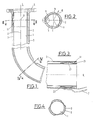
- the inner pipe 1 is guided on the casing pipe 3 with a sliding seat.
- a structural design of the sliding seats can be seen particularly clearly in the sectional views in FIGS. 2, 3, except in the longitudinal sectional view of FIG. 1.
- An essential component of this sliding seat is the presence of spacer elements arranged between the inner tube 1 and the casing tube 3 and distributed over the course of the annular gap 2. These spacer elements create an additional one in the sliding seat area Angular mobility between the inner tube 1 and the casing tube 3 about a sliding seat center 9, which is intended in the area of the tube axis 8.
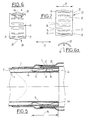
- Embodiments of the spacer elements according to the invention are the subject of, in particular, FIGS. 5 to 11.
- the spacer elements can bear against the concave side 12 of an annular body 13-15 which has the cross-sectional shape of a flat channel, for example.
- 13 an inner ring body is designated, which is welded to the outer circumference of the inner tube 1.
- an outer ring body is designated, which is welded to the inner surface of the casing tube 3 (Fig. 8).
- the ring bodies 13-15 are fastened with the bottom jacket 16 facing away from their concave sides 12 to a tube wall delimiting the air ring gap 2. In the case of the inner ring body 13, this is the outer wall of the inner tube 1.
- the ring bodies 13-15 consist of metallic material, in particular of the same material as the inner tube 1 or jacket tube 3 that supports them. They have the shape of a cylinder with contact flanges 44 which are bent radially inwards or outwards at both cylinder ends.
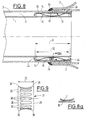
- the ring bodies 13-15 are slotted transversely to their circumferential direction 17.
- An annular slot 18 is shown in FIG. 11 using the annular body 15.
- the spacer elements are formed by circumferential regions of the spring ring sleeve 20, 21 lying in the ring groove 19 facing away from the channel bottom 12 (FIGS. 5 to 7; 8 and 9).
- the inner ring body 13 is welded with its bottom jacket 16 to the outer jacket of the inner tube 1.
- the spring ring sleeve 20 lying in its annular groove 19 is made of spring steel existing, essentially cylindrical sleeve with a plurality of cuffs distributed over the circumference of the sleeve, extending in the axial direction 22 between two ring ends 23, 24, bulging radially outwards, effective in the manner of spring lamellae, bridge webs 25, which bear against the inner wall of the casing tube 3, while it is supported with its ring ends 23, 24 on the inner ring body 13 or on the inner tube 1.
- the cross section of a bridge web 25 has the shape of approximately a segment of a circle with a bending radius 45 which is significantly smaller than half the inside diameter of the casing tube 3, the convex side of the segment of the circle facing the inside of the casing tube 3.
- the ring ends 23, 24 of the spring ring sleeve 20 lying outside the bridge webs 25 can be circumferentially closed without being slotted.
- Another embodiment provides that the spring ring sleeve 20 is slotted through a slot 46.
- the spring ring sleeve 20 can expand circumferentially unhindered under the influence of the heating of the inner tube 1.
- the spring ring sleeve 21 described below can be slotted transversely to its circumferential direction in the manner of the slot 46, even if this is not shown in detail in FIG. 9.
- the clear channel width 26 (FIG. 5) between the contact flanges 44 of the ring body 13 is greater than the width 27 of the spring ring 20.
- the embodiment of the spring ring sleeve 21 according to FIGS. 8 to 9 has the advantage that, without further precautions, the bridge webs 30 between the two ring ends 28, 29 assume the cross-sectional shape of a rectangle, the long side of which lies approximately tangentially on the outer circumference of the inner tube 1 (Fig. 8a). It is assumed here that the spring washer sleeve 21, like the spring washer sleeve 20, is made from a sheet metal strip made of spring sheet metal by stamping and bending with the bridge webs 25 and 30 and by welding its narrow ends to form a circumferentially closed ring Bridge webs 30 automatically result in the approximately rectangular cross-sectional shape shown in FIG.
- the spring ring 20 (FIG. 6, 7) requires additional precautions in order to give the bridge webs 25 the arched cross-sectional shape that can be seen in FIG. 6 a, which is the approximate point contact in the region of the bridge webs 25 that is ideal for both spring ring shapes 20, 21 or 30 on the counter tube jacket.
- the ring ends 28, 29 of the spring ring sleeve 21 lying outside the bridge webs 30 can also be closed in their entirety without slits.
- the clear channel width 31 is larger than the width 32 of the spring ring sleeve 21.
- the contact surfaces 35 of the ring ends 23, 24 of the spring ring sleeve 20 and the contact surfaces 36 of the ring ends 28, 29 of the spring ring sleeve 21 have a cross-sectional shape that is convex in the direction of the adjacent pipe surface (FIGS. 5 to 7; 8).
- This design also has the task of creating an ideal, small-area contact situation with the ring body, namely essentially at least one line contact.
- the embodiment according to FIGS. 8 to 9 with bridge webs 30 of the spring ring sleeve 21 acting on the inner tube 1 has the further advantage that the inner tube 1 consisting of the more valuable material can have a shorter length than the jacket tube 3 on the catalytic converter side.
- 10 and 11 show embodiments in which the spring ring sleeves 20, 21 are connected directly to the inner tube 1 or the jacket tube 3.
- the spring washers 20 and 21 are with one of their two radial ring ends 28, 29, namely in the area of their contact surfaces 35, 36 or with their bridge webs 25, 30 on the inner tube 1 (FIG. 11) or on the casing tube (3) (FIG 10) welded on.
- Reference list 1 Inner tube 2nd Air ring gap 44 Contact flange 3rd Casing pipe 45 Bending radius 4th Engine end 46 slot 5 Mounting flange 6 catalyst side end 7 Catalytic converter housing 8th Pipe axis 9 Sliding seat center 10th Radial direction 11 Bulge 12th Concave side 13 Ring body 14 Ring body 15 Ring body 16 Floor mantle 17th Circumferential direction 18th Ring slot 19th Ring gutter 20th Spring washer 21 Spring washer 22 Axial direction 23 Ring end 24th Ring end 25th Footbridge 26 Gutter width 27 width 28 Ring end 29 Ring end 30th Footbridge 31 Gutter width 32 width 33 Weld 34 Ring weld 35 Investment surface 36 Investment surface
Claims (9)
- Conduit d'échappement isolé par une couche d'air et formant le conduit des gaz d'échappement entre le moteur et le catalyseur d'une automobile(a) comportant un tube intérieur (1),(b) comportant un tube-enveloppe (3) qui porte le tube intérieur (1) et l'entoure en laissant une couche d'air annulaire (2) et(c) comportant une assise de coulissement pour guider le tube intérieur (1) contre le tube-enveloppe (3),
caractérisé par le fait(d) que l'assise de coulissement est formée par des éléments écarteurs- disposés répartis sur la périphérie de la couche d'air annulaire (2),- écartant le tube intérieur (1) du tube-enveloppe (3) et- tenus sous une pression de précontrainte radiale, en particulier une pression élastique radiale,(e) que les éléments écarteurs sont formés par un manchon annulaire élastique (20̸, 21) qui est introduit dans la couche d'air annulaire (2),- qui, dans une zone médiane située entre ses extrémités annulaires axiales (23, 24; 28, 29), présente, réparties sur sa périphérie, des fentes orientées sensiblement selon la direction axiale et- dont les barrettes de pontage (25, 30̸) entre les fentes voisines et entre les extrémités annulaires (23, 24; 28, 29) sont bombées radialement vers l'intérieur ou vers l'extérieur,(f) que le manchon annulaire élastique (20̸, 21) s'appuie, sous pression de précontrainte, par ses extrémités annulaires axiales (23, 24; 28, 29), contre un tube et, par ses barrettes de pontage (25, 30̸) situées entre ses extrémités et bombées, contre l'autre tube (1 ou 3) et(g) que, par l'une de ses extrémités annulaires axiales (23, 24) ou par au moins une barrette de pontage (25, 30̸), le manchon annulaire élastique (20̸, 21) soit relié, en particulier soudé, au tube (1 ou 3) contre lequel il s'appuie. - Conduit selon la revendication 1,
caractérisé par le fait que, par l'une de ses extrémités annulaires axiales (23, 24) ou par au moins une barrette de pontage (25, 30̸), le manchon annulaire élastique (20̸, 21) est relié, par une liaison de soudage par points, au tube (1 ou 3) contre lequel il s'appuie. - Conduit selon la revendication 1,
caractérisé par le fait que le manchon annulaire élastique (20̸, 21) est relié à un tube (1 ou 3) par un cordon de soudure en forme d'anneau au moins partiel, à l'une de ses extrémités annulaires axiales (23, 24), dans sa zone d'appui contre ce tuyau. - Conduit selon une ou plusieurs des revendications précédentes,
caractérisé
par le fait qu'au moins une barrette de pontage (25) a en coupe à peu près la forme d'un segment circulaire dont le rayon de courbure (45) est inférieur au demi-diamètre intérieur, à savoir le rayon de courbure du tube-enveloppe (3) et que la barrette de pontage (25) s'appuie contre le tube-enveloppe (3) par la face convexe de sa forme en coupe. - Conduit selon l'une des revendications 1 à 4,
caractérisé
par le fait que les extrémités annulaires axiales (23, 24), du manchon annulaire élastique (20̸, 21) situées à l'extérieur des barrettes de pontage (25) ne sont pas fendues et sont fermées en soi sur la périphérie. - Conduit selon l'une des revendications 1 à 4,
caractérisé
par le fait que les extrémité annulaires (23, 24; 28, 29) du manchon annulaire élastique (20̸, 21) sont fendues dans le prolongement d'une fente (46). - Conduit selon une ou plusieurs des revendications précédentes,
caractérisé
par une forme en coupe des faces d'appui (35, 36) des extrémités annulaires (23, 24; 28, 29) du manchon annulaire élastique (20̸, 21) qui présente un bombement convexe en direction de la paroi adjacente d'un tube (1 ou 3). - Conduit selon une ou plusieurs des revendications précédentes,
caractérisé
par le fait que l'assise de coulissement est disposée à son extrémité (6) située du côté du catalyseur et qu'à cet endroit le carter (7) du catalyseur est soudé à la périphérie extérieure de son tube-eneveloppe (3). - Conduit selon une ou plusieurs des revendications précédentes,
caractérisé
par le fait que le tube intérieur (1) est fixé au tube-enveloppe (3) entre les deux extrémités (4, 6) du conduit et qu'aux deux extrémités, il est guidé contre le tube-enveloppe (3) par une assise de coulissement.
Applications Claiming Priority (2)
| Application Number | Priority Date | Filing Date | Title |
|---|---|---|---|
| DE9102926U DE9102926U1 (fr) | 1991-03-12 | 1991-03-12 | |
| DE9102926U | 1991-03-12 |
Publications (2)
| Publication Number | Publication Date |
|---|---|
| EP0508145A1 EP0508145A1 (fr) | 1992-10-14 |
| EP0508145B1 true EP0508145B1 (fr) | 1994-12-07 |
Family
ID=6865144
Family Applications (2)
| Application Number | Title | Priority Date | Filing Date |
|---|---|---|---|
| EP92104145A Expired - Lifetime EP0503580B1 (fr) | 1991-03-12 | 1992-03-11 | Conduit d'échappement isolé par une couche d'air |
| EP92104258A Expired - Lifetime EP0508145B1 (fr) | 1991-03-12 | 1992-03-12 | Conduit d'échappement isolé par une couche d'air |
Family Applications Before (1)
| Application Number | Title | Priority Date | Filing Date |
|---|---|---|---|
| EP92104145A Expired - Lifetime EP0503580B1 (fr) | 1991-03-12 | 1992-03-11 | Conduit d'échappement isolé par une couche d'air |
Country Status (3)
| Country | Link |
|---|---|
| EP (2) | EP0503580B1 (fr) |
| DE (3) | DE9102926U1 (fr) |
| ES (1) | ES2075503T3 (fr) |
Cited By (1)
| Publication number | Priority date | Publication date | Assignee | Title |
|---|---|---|---|---|
| EP0662564B2 (fr) † | 1994-01-07 | 2001-09-26 | J. Eberspächer GmbH & Co. | Conduit de gaz d'échappement isolé par une couche d'air et méthode de construction |
Families Citing this family (19)
| Publication number | Priority date | Publication date | Assignee | Title |
|---|---|---|---|---|
| DE9102926U1 (fr) * | 1991-03-12 | 1991-08-08 | Leistritz Ag & Co Abgastechnik, 8510 Fuerth, De | |
| DE4134466A1 (de) * | 1991-10-18 | 1993-04-22 | Eberspaecher J | Doppelwandiges luftisoliertes rohr fuer abgasanlagen in fahrzeugen |
| DE4229467A1 (de) * | 1992-09-03 | 1994-03-10 | Mtu Friedrichshafen Gmbh | Lagereinrichtung für die Abgassammelleitung einer Brennkraftmaschine |
| DE19606003A1 (de) * | 1996-02-17 | 1997-06-12 | Daimler Benz Ag | Schiebesitz-Rohrverbindung |
| DE19722037A1 (de) * | 1997-05-27 | 1998-12-03 | Hecralmat Fa | Hitzeschild mit Schallisolierung |
| US6155046A (en) * | 1998-04-20 | 2000-12-05 | Honda Giken Kogyo Kabushiki Kaisha | Heat-insulation type exhaust manifold |
| EP1091101B1 (fr) * | 1999-10-08 | 2004-12-29 | Kabushiki Kaisha Yutaka Giken | Système de ligne d'échappement à conduit double |
| JP2002155720A (ja) * | 2000-11-20 | 2002-05-31 | Yamaha Motor Co Ltd | ブローバイガス還元装置のユニオン構造 |
| DE10105841C2 (de) * | 2001-02-07 | 2002-12-12 | Benteler Automobiltechnik Gmbh | Abgasleitung mit Luftspaltisolierung für eine Brennkraftmaschine |
| DE10357344A1 (de) * | 2003-12-09 | 2005-07-14 | Daimlerchrysler Ag | Luftspaltisoliertes Abgasrohr, und Verfahren zu dessen Herstellung |
| DE102009059684A1 (de) | 2009-12-19 | 2011-06-22 | J. Eberspächer GmbH & Co. KG, 73730 | Abgasbehandlungseinrichtung |
| DE102010040249A1 (de) * | 2010-09-03 | 2012-03-08 | Man Diesel & Turbo Se | Doppelwandiges Rohr |
| DE102011012595A1 (de) * | 2011-02-28 | 2012-08-30 | Faurecia Emissions Control Technologies, Germany Gmbh | Luftspaltisolierte Abgasleitung |
| DE102012021063A1 (de) * | 2012-10-20 | 2014-04-24 | Daimler Ag | Luftspaltisolierte Abgasrohreinheit und Verfahren zur Herstellung |
| DE102014018127A1 (de) | 2014-12-06 | 2016-06-09 | Daimler Ag | Verbindungsanordnung eines luftspaltisolierten Abgasführungselements an einem weiteren Abgasführungselement |
| DE102015112560A1 (de) * | 2015-07-30 | 2017-02-02 | Elringklinger Ag | Dichtungsvorrichtung |
| CN108240512A (zh) * | 2016-12-26 | 2018-07-03 | 天津市科瑞燃气设备有限公司 | 一种燃气管道进气管 |
| EP3599405A1 (fr) * | 2018-07-25 | 2020-01-29 | Holter Regelarmaturen GmbH & Co. KG | Conduite destinée à conduire le passage d'un fluide chaud |
| CN111895224B (zh) * | 2020-07-10 | 2022-02-11 | 中国兵器工业第五九研究所 | 一种模块化保温壳结构 |
Citations (1)
| Publication number | Priority date | Publication date | Assignee | Title |
|---|---|---|---|---|
| EP0503580A1 (fr) * | 1991-03-12 | 1992-09-16 | LEISTRITZ AG & CO. Abgastechnik | Conduit d'échappement isolé par une couche d'air |
Family Cites Families (7)
| Publication number | Priority date | Publication date | Assignee | Title |
|---|---|---|---|---|
| FR1394743A (fr) * | 1963-09-16 | 1965-04-09 | Petrole Chimie Soc | Colliers isolateurs élastiques pour pipe-lines |
| DE2452556A1 (de) * | 1974-11-06 | 1976-05-13 | Audi Nsu Auto Union Ag | Vorrichtung zum entgiften der abgase von brennkraftmaschinen |
| US4185463A (en) * | 1976-05-18 | 1980-01-29 | Toyota Jibosha Kogyo Kabushiki Kaisha | Exhaust double pipe of an internal combustion engine |
| US4250927A (en) * | 1979-08-24 | 1981-02-17 | Piper Aircraft Corporation | Duct spacer clip and duct assembly |
| DE3017574C2 (de) * | 1980-05-08 | 1985-06-05 | Wieland-Werke Ag, 7900 Ulm | Abstandshalter für koaxiale Wärmeübertrager |
| US4607665A (en) * | 1985-05-20 | 1986-08-26 | Marco Manufacturing, Inc. | Pipe spacer |
| DE8912161U1 (fr) * | 1989-10-12 | 1991-02-07 | Zeuna-Staerker Gmbh & Co Kg, 8900 Augsburg, De |
-
1991
- 1991-03-12 DE DE9102926U patent/DE9102926U1/de not_active Expired - Lifetime
-
1992
- 1992-03-11 DE DE59202891T patent/DE59202891D1/de not_active Expired - Fee Related
- 1992-03-11 ES ES92104145T patent/ES2075503T3/es not_active Expired - Lifetime
- 1992-03-11 EP EP92104145A patent/EP0503580B1/fr not_active Expired - Lifetime
- 1992-03-12 DE DE59200885T patent/DE59200885D1/de not_active Expired - Fee Related
- 1992-03-12 EP EP92104258A patent/EP0508145B1/fr not_active Expired - Lifetime
Patent Citations (1)
| Publication number | Priority date | Publication date | Assignee | Title |
|---|---|---|---|---|
| EP0503580A1 (fr) * | 1991-03-12 | 1992-09-16 | LEISTRITZ AG & CO. Abgastechnik | Conduit d'échappement isolé par une couche d'air |
Cited By (1)
| Publication number | Priority date | Publication date | Assignee | Title |
|---|---|---|---|---|
| EP0662564B2 (fr) † | 1994-01-07 | 2001-09-26 | J. Eberspächer GmbH & Co. | Conduit de gaz d'échappement isolé par une couche d'air et méthode de construction |
Also Published As
| Publication number | Publication date |
|---|---|
| EP0503580B1 (fr) | 1995-07-19 |
| EP0503580A1 (fr) | 1992-09-16 |
| EP0508145A1 (fr) | 1992-10-14 |
| DE59202891D1 (de) | 1995-08-24 |
| ES2075503T3 (es) | 1995-10-01 |
| DE9102926U1 (fr) | 1991-08-08 |
| DE59200885D1 (de) | 1995-01-19 |
Similar Documents
| Publication | Publication Date | Title |
|---|---|---|
| EP0508145B1 (fr) | Conduit d'échappement isolé par une couche d'air | |
| EP0212331B1 (fr) | Raccordement de deux tuyaux d'une conduite pour milieux chauds | |
| EP1887194B1 (fr) | Dispositif de purification de gas d'échappement | |
| DE102008052552B4 (de) | Turbinengehäuse und Verfahren zu seiner Herstellung | |
| EP0615595B1 (fr) | Dispositif de raccordement flexible pour deux elements tubulaires, notamment pour systemes de gaz d'echappement de vehicules | |
| EP0582985B1 (fr) | Collecteur d'échappement | |
| EP0683851B1 (fr) | Element metallique alveole maintenu dans un tube de protection interieur et exterieur, notamment element-support de catalyseur | |
| EP0580963B1 (fr) | Conduite articulée | |
| EP0797039A2 (fr) | Elément de tuyua avec soufflet métallique | |
| EP3365562B1 (fr) | Élément en forme de plaque muni d'un dispositif de fixation traversant l'élément en forme de plaque | |
| EP0537603B1 (fr) | Tuyau à paroi double, isolé par de l'air, pour des installations d'échappement de véhicules | |
| EP2066909A1 (fr) | Cage pour palier à roulement et son procédé de fabrication | |
| EP0881422A1 (fr) | Elément de conduite avec au moins deux soufflets et un tuyau intermédiaire les connectant | |
| EP0681097B1 (fr) | Elément de connexion flexible pour éléments tubulaires | |
| EP0208128A1 (fr) | Connexion articulée d'éléments de tube, notamment dans des conduits d'échappement de véhicules automobiles | |
| EP1048881B1 (fr) | Conduite de produit réfrigérant pour conditionneurs d'air | |
| EP1149992A1 (fr) | Ensemble d'échappement pour un système de gaz d'échappement, en particulier catalyseur de gaz d'échappement à construction modulaire pour véhicule | |
| EP0573764B1 (fr) | Joint articulé d'éléments de tube, notamment dans des conduits d'échappement de véhicules automobiles | |
| EP0398086B1 (fr) | Raccordement pour deux tuyaux d'un conduit pour médium chaud | |
| EP0747582A2 (fr) | Elément de découplage pour les vibrations dans les conduits | |
| EP0983425B1 (fr) | Systeme permettant d'eviter les vibrations mecaniques | |
| EP1571396B1 (fr) | Dispositif d'étanchéité pour une chambre de combustion de turbine à gaz | |
| EP1859132B1 (fr) | Boitier d'un composant de traitement des gaz d'echappement dote d'une douille de renforcement | |
| DE4202079C2 (de) | Abgasanlage für Brennkraftmaschinen | |
| DE3526481A1 (de) | Verbindung zweier rohrenden durch ein wellrohr |
Legal Events
| Date | Code | Title | Description |
|---|---|---|---|
| PUAI | Public reference made under article 153(3) epc to a published international application that has entered the european phase |
Free format text: ORIGINAL CODE: 0009012 |
|
| AK | Designated contracting states |
Kind code of ref document: A1 Designated state(s): AT BE CH DE DK ES FR GB GR IT LI LU MC NL PT SE |
|
| RBV | Designated contracting states (corrected) |
Designated state(s): BE DE DK ES FR GB GR IT LU NL PT SE |
|
| 17P | Request for examination filed |
Effective date: 19921125 |
|
| 17Q | First examination report despatched |
Effective date: 19930113 |
|
| GRAA | (expected) grant |
Free format text: ORIGINAL CODE: 0009210 |
|
| AK | Designated contracting states |
Kind code of ref document: B1 Designated state(s): BE DE DK ES FR GB GR IT LU NL PT SE |
|
| PG25 | Lapsed in a contracting state [announced via postgrant information from national office to epo] |
Ref country code: IT Free format text: LAPSE BECAUSE OF FAILURE TO SUBMIT A TRANSLATION OF THE DESCRIPTION OR TO PAY THE FEE WITHIN THE PRE;WARNING: LAPSES OF ITALIAN PATENTS WITH EFFECTIVE DATE BEFORE 2007 MAY HAVE OCCURRED AT ANY TIME BEFORE 2007. THE CORRECT EFFECTIVE DATE MAY BE DIFFERENT FROM THE ONE RECORDED.SCRIBED TIME-LIMIT Effective date: 19941207 Ref country code: GR Free format text: LAPSE BECAUSE OF FAILURE TO SUBMIT A TRANSLATION OF THE DESCRIPTION OR TO PAY THE FEE WITHIN THE PRESCRIBED TIME-LIMIT Effective date: 19941207 Ref country code: NL Effective date: 19941207 Ref country code: ES Free format text: THE PATENT HAS BEEN ANNULLED BY A DECISION OF A NATIONAL AUTHORITY Effective date: 19941207 Ref country code: DK Effective date: 19941207 Ref country code: GB Effective date: 19941207 Ref country code: BE Effective date: 19941207 |
|
| REF | Corresponds to: |
Ref document number: 59200885 Country of ref document: DE Date of ref document: 19950119 |
|
| PG25 | Lapsed in a contracting state [announced via postgrant information from national office to epo] |
Ref country code: PT Effective date: 19950307 Ref country code: SE Effective date: 19950307 |
|
| ET | Fr: translation filed | ||
| PG25 | Lapsed in a contracting state [announced via postgrant information from national office to epo] |
Ref country code: LU Free format text: LAPSE BECAUSE OF NON-PAYMENT OF DUE FEES Effective date: 19950331 |
|
| NLV1 | Nl: lapsed or annulled due to failure to fulfill the requirements of art. 29p and 29m of the patents act | ||
| GBV | Gb: ep patent (uk) treated as always having been void in accordance with gb section 77(7)/1977 [no translation filed] |
Effective date: 19941207 |
|
| PLBE | No opposition filed within time limit |
Free format text: ORIGINAL CODE: 0009261 |
|
| STAA | Information on the status of an ep patent application or granted ep patent |
Free format text: STATUS: NO OPPOSITION FILED WITHIN TIME LIMIT |
|
| 26N | No opposition filed | ||
| PGFP | Annual fee paid to national office [announced via postgrant information from national office to epo] |
Ref country code: FR Payment date: 19980317 Year of fee payment: 7 |
|
| PGFP | Annual fee paid to national office [announced via postgrant information from national office to epo] |
Ref country code: DE Payment date: 19980408 Year of fee payment: 7 |
|
| PG25 | Lapsed in a contracting state [announced via postgrant information from national office to epo] |
Ref country code: FR Free format text: LAPSE BECAUSE OF NON-PAYMENT OF DUE FEES Effective date: 19991130 |
|
| REG | Reference to a national code |
Ref country code: FR Ref legal event code: ST |
|
| PG25 | Lapsed in a contracting state [announced via postgrant information from national office to epo] |
Ref country code: DE Free format text: LAPSE BECAUSE OF NON-PAYMENT OF DUE FEES Effective date: 20000101 |