EP0508145B1 - Exhaust pipe with air gap insulation - Google Patents
Exhaust pipe with air gap insulation Download PDFInfo
- Publication number
- EP0508145B1 EP0508145B1 EP92104258A EP92104258A EP0508145B1 EP 0508145 B1 EP0508145 B1 EP 0508145B1 EP 92104258 A EP92104258 A EP 92104258A EP 92104258 A EP92104258 A EP 92104258A EP 0508145 B1 EP0508145 B1 EP 0508145B1
- Authority
- EP
- European Patent Office
- Prior art keywords
- pipe
- bridging
- tube
- spring collar
- feeder
- Prior art date
- Legal status (The legal status is an assumption and is not a legal conclusion. Google has not performed a legal analysis and makes no representation as to the accuracy of the status listed.)
- Expired - Lifetime
Links
Images

Classifications
-
- F—MECHANICAL ENGINEERING; LIGHTING; HEATING; WEAPONS; BLASTING
- F01—MACHINES OR ENGINES IN GENERAL; ENGINE PLANTS IN GENERAL; STEAM ENGINES
- F01N—GAS-FLOW SILENCERS OR EXHAUST APPARATUS FOR MACHINES OR ENGINES IN GENERAL; GAS-FLOW SILENCERS OR EXHAUST APPARATUS FOR INTERNAL COMBUSTION ENGINES
- F01N13/00—Exhaust or silencing apparatus characterised by constructional features ; Exhaust or silencing apparatus, or parts thereof, having pertinent characteristics not provided for in, or of interest apart from, groups F01N1/00 - F01N5/00, F01N9/00, F01N11/00
- F01N13/08—Other arrangements or adaptations of exhaust conduits
-
- F—MECHANICAL ENGINEERING; LIGHTING; HEATING; WEAPONS; BLASTING
- F01—MACHINES OR ENGINES IN GENERAL; ENGINE PLANTS IN GENERAL; STEAM ENGINES
- F01N—GAS-FLOW SILENCERS OR EXHAUST APPARATUS FOR MACHINES OR ENGINES IN GENERAL; GAS-FLOW SILENCERS OR EXHAUST APPARATUS FOR INTERNAL COMBUSTION ENGINES
- F01N13/00—Exhaust or silencing apparatus characterised by constructional features ; Exhaust or silencing apparatus, or parts thereof, having pertinent characteristics not provided for in, or of interest apart from, groups F01N1/00 - F01N5/00, F01N9/00, F01N11/00
- F01N13/14—Exhaust or silencing apparatus characterised by constructional features ; Exhaust or silencing apparatus, or parts thereof, having pertinent characteristics not provided for in, or of interest apart from, groups F01N1/00 - F01N5/00, F01N9/00, F01N11/00 having thermal insulation
- F01N13/141—Double-walled exhaust pipes or housings
-
- F—MECHANICAL ENGINEERING; LIGHTING; HEATING; WEAPONS; BLASTING
- F16—ENGINEERING ELEMENTS AND UNITS; GENERAL MEASURES FOR PRODUCING AND MAINTAINING EFFECTIVE FUNCTIONING OF MACHINES OR INSTALLATIONS; THERMAL INSULATION IN GENERAL
- F16L—PIPES; JOINTS OR FITTINGS FOR PIPES; SUPPORTS FOR PIPES, CABLES OR PROTECTIVE TUBING; MEANS FOR THERMAL INSULATION IN GENERAL
- F16L59/00—Thermal insulation in general
- F16L59/14—Arrangements for the insulation of pipes or pipe systems
- F16L59/16—Arrangements specially adapted to local requirements at flanges, junctions, valves or the like
- F16L59/21—Arrangements specially adapted to local requirements at flanges, junctions, valves or the like adapted for expansion-compensation devices
-
- F—MECHANICAL ENGINEERING; LIGHTING; HEATING; WEAPONS; BLASTING
- F01—MACHINES OR ENGINES IN GENERAL; ENGINE PLANTS IN GENERAL; STEAM ENGINES
- F01N—GAS-FLOW SILENCERS OR EXHAUST APPARATUS FOR MACHINES OR ENGINES IN GENERAL; GAS-FLOW SILENCERS OR EXHAUST APPARATUS FOR INTERNAL COMBUSTION ENGINES
- F01N2470/00—Structure or shape of gas passages, pipes or tubes
- F01N2470/24—Concentric tubes or tubes being concentric to housing, e.g. telescopically assembled
Definitions
- the invention relates to an air gap-insulated front pipe as an exhaust line between the engine and catalytic converter of an automobile with the features listed in the preamble of claim 1.
- the inner pipe is made comparatively thin-walled for reasons of mass reduction in order to remove as little heat as possible from the exhaust gas in direct contact with it. It is made of high quality material, especially steel.
- the jacket tube surrounding the inner tube while leaving the heat-insulating air annular gap responsible is also responsible for the support function for the inner tube.
- the connecting flange for the exhaust gas connector of the engine is fastened, in particular welded, to the casing pipe.
- the casing tube forms the insertion end of the front tube into the catalytic converter housing.
- the jacket tube consists of a simple, inexpensive material, in particular steel, and is of comparatively thick-walled design for reasons of stability.
- the inner pipe is firmly connected to the jacket pipe at the engine-side end, while it is guided at the other, catalyst-side end with a sliding seat in the jacket pipe.
- the jacket tube has a constriction of diameter extending over a certain length range.
- the relative mobility between the inner tube and the jacket tube in the axial direction of the front tube, which is made possible by this sliding seat, is necessary in order to allow compensation for the different thermal expansions of the inner tube and the jacket tube during engine operation. These different thermal expansions are inevitable because of the different temperature levels of the inner tube and the jacket tube.
- a sliding seat for guiding the inner pipe in the casing pipe is also provided.
- the inner tube is fixed to the jacket tube so that it lies in place.
- the inner tube is guided in a longitudinally displaceable manner in the jacket tube with the interposition of a bearing ring.
- the inner tube has a cylindrical tube section which serves as a sliding surface for the bearing ring for length compensation of the thermal expansion of the inner tube.
- the outer tube has a conical tube section which widens in the direction of expansion of the inner tube.
- the bearing ring consists of compressed wire mesh.
- a spacer for a heat exchanger consisting of an outer tube and a concentric inner tube between liquids or gases is known with a tubular sleeve which is held on the inner tube and extends over at least three substantially radial, evenly around the central axis distributed support elements supported on the outer tube.
- the sleeve of this plastic spacer is slotted in the longitudinal direction in such a way that the spacer can be clipped onto the inner tube.
- the tubular sleeve of the spacer can also consist of two axially spaced parts which are connected to one another via curved support elements.
- the invention has for its object to arrange and guide the inner tube within the jacket tube so that it can move unhindered relative to the jacket tube due to its thermal expansion.
- This object is achieved in accordance with the characterizing part of claim 1 by spacer elements arranged in the sliding seat area, which, in addition to the longitudinal displaceability, enable an additional angular mobility between the inner and outer tube.
- spacer elements thus give the sliding seat an effectiveness comparable to the function of a self-aligning ball bearing, in that the inner tube not only moves axially with respect to the casing tube, but also pivots about the center of the bearing can adjust.
- the sliding seat is also insensitive to misalignments between the inner tube and the outer tube and to bending movements of the inner tube relative to the outer tube.
- the inner pipe 1 is guided on the casing pipe 3 with a sliding seat.
- a structural design of the sliding seats can be seen particularly clearly in the sectional views in FIGS. 2, 3, except in the longitudinal sectional view of FIG. 1.
- An essential component of this sliding seat is the presence of spacer elements arranged between the inner tube 1 and the casing tube 3 and distributed over the course of the annular gap 2. These spacer elements create an additional one in the sliding seat area Angular mobility between the inner tube 1 and the casing tube 3 about a sliding seat center 9, which is intended in the area of the tube axis 8.
- Embodiments of the spacer elements according to the invention are the subject of, in particular, FIGS. 5 to 11.
- the spacer elements can bear against the concave side 12 of an annular body 13-15 which has the cross-sectional shape of a flat channel, for example.
- 13 an inner ring body is designated, which is welded to the outer circumference of the inner tube 1.
- an outer ring body is designated, which is welded to the inner surface of the casing tube 3 (Fig. 8).
- the ring bodies 13-15 are fastened with the bottom jacket 16 facing away from their concave sides 12 to a tube wall delimiting the air ring gap 2. In the case of the inner ring body 13, this is the outer wall of the inner tube 1.
- the ring bodies 13-15 consist of metallic material, in particular of the same material as the inner tube 1 or jacket tube 3 that supports them. They have the shape of a cylinder with contact flanges 44 which are bent radially inwards or outwards at both cylinder ends.
- the ring bodies 13-15 are slotted transversely to their circumferential direction 17.
- An annular slot 18 is shown in FIG. 11 using the annular body 15.
- the spacer elements are formed by circumferential regions of the spring ring sleeve 20, 21 lying in the ring groove 19 facing away from the channel bottom 12 (FIGS. 5 to 7; 8 and 9).
- the inner ring body 13 is welded with its bottom jacket 16 to the outer jacket of the inner tube 1.
- the spring ring sleeve 20 lying in its annular groove 19 is made of spring steel existing, essentially cylindrical sleeve with a plurality of cuffs distributed over the circumference of the sleeve, extending in the axial direction 22 between two ring ends 23, 24, bulging radially outwards, effective in the manner of spring lamellae, bridge webs 25, which bear against the inner wall of the casing tube 3, while it is supported with its ring ends 23, 24 on the inner ring body 13 or on the inner tube 1.
- the cross section of a bridge web 25 has the shape of approximately a segment of a circle with a bending radius 45 which is significantly smaller than half the inside diameter of the casing tube 3, the convex side of the segment of the circle facing the inside of the casing tube 3.
- the ring ends 23, 24 of the spring ring sleeve 20 lying outside the bridge webs 25 can be circumferentially closed without being slotted.
- Another embodiment provides that the spring ring sleeve 20 is slotted through a slot 46.
- the spring ring sleeve 20 can expand circumferentially unhindered under the influence of the heating of the inner tube 1.
- the spring ring sleeve 21 described below can be slotted transversely to its circumferential direction in the manner of the slot 46, even if this is not shown in detail in FIG. 9.
- the clear channel width 26 (FIG. 5) between the contact flanges 44 of the ring body 13 is greater than the width 27 of the spring ring 20.
- the embodiment of the spring ring sleeve 21 according to FIGS. 8 to 9 has the advantage that, without further precautions, the bridge webs 30 between the two ring ends 28, 29 assume the cross-sectional shape of a rectangle, the long side of which lies approximately tangentially on the outer circumference of the inner tube 1 (Fig. 8a). It is assumed here that the spring washer sleeve 21, like the spring washer sleeve 20, is made from a sheet metal strip made of spring sheet metal by stamping and bending with the bridge webs 25 and 30 and by welding its narrow ends to form a circumferentially closed ring Bridge webs 30 automatically result in the approximately rectangular cross-sectional shape shown in FIG.
- the spring ring 20 (FIG. 6, 7) requires additional precautions in order to give the bridge webs 25 the arched cross-sectional shape that can be seen in FIG. 6 a, which is the approximate point contact in the region of the bridge webs 25 that is ideal for both spring ring shapes 20, 21 or 30 on the counter tube jacket.
- the ring ends 28, 29 of the spring ring sleeve 21 lying outside the bridge webs 30 can also be closed in their entirety without slits.
- the clear channel width 31 is larger than the width 32 of the spring ring sleeve 21.
- the contact surfaces 35 of the ring ends 23, 24 of the spring ring sleeve 20 and the contact surfaces 36 of the ring ends 28, 29 of the spring ring sleeve 21 have a cross-sectional shape that is convex in the direction of the adjacent pipe surface (FIGS. 5 to 7; 8).
- This design also has the task of creating an ideal, small-area contact situation with the ring body, namely essentially at least one line contact.
- the embodiment according to FIGS. 8 to 9 with bridge webs 30 of the spring ring sleeve 21 acting on the inner tube 1 has the further advantage that the inner tube 1 consisting of the more valuable material can have a shorter length than the jacket tube 3 on the catalytic converter side.
- 10 and 11 show embodiments in which the spring ring sleeves 20, 21 are connected directly to the inner tube 1 or the jacket tube 3.
- the spring washers 20 and 21 are with one of their two radial ring ends 28, 29, namely in the area of their contact surfaces 35, 36 or with their bridge webs 25, 30 on the inner tube 1 (FIG. 11) or on the casing tube (3) (FIG 10) welded on.
- Reference list 1 Inner tube 2nd Air ring gap 44 Contact flange 3rd Casing pipe 45 Bending radius 4th Engine end 46 slot 5 Mounting flange 6 catalyst side end 7 Catalytic converter housing 8th Pipe axis 9 Sliding seat center 10th Radial direction 11 Bulge 12th Concave side 13 Ring body 14 Ring body 15 Ring body 16 Floor mantle 17th Circumferential direction 18th Ring slot 19th Ring gutter 20th Spring washer 21 Spring washer 22 Axial direction 23 Ring end 24th Ring end 25th Footbridge 26 Gutter width 27 width 28 Ring end 29 Ring end 30th Footbridge 31 Gutter width 32 width 33 Weld 34 Ring weld 35 Investment surface 36 Investment surface
Description
Die Erfindung betrifft ein luftspaltisoliertes Vorrohr als Abgasstrang zwischen Motor und Katalysator eines Automobils mit den im Oberbegriff des Anspruches 1 aufgeführten Merkmalen.The invention relates to an air gap-insulated front pipe as an exhaust line between the engine and catalytic converter of an automobile with the features listed in the preamble of
Bei einem bekannten Vorrohr dieser Art ist das Innenrohr aus Gründen der Massereduzierung vergleichsweise dünnwandig ausgeführt, um dem mit ihm in unmittelbarem Kontakt stehenden Abgas möglichst wenig Wärme zu entziehen. Es besteht aus hochwertigem Werkstoff, insbesondere aus Stahl. Dem das Innenrohr unter Belassung des wärmeisolierenden Luft-Ringspaltes umgebenden Mantelrohr obliegt neben der Wärmeisolationsfunktion die Trägerfunktion für das Innenrohr. Am Mantelrohr ist beispielsweise der Verbindungsflansch zum Abgasstutzen des Motors befestigt, insbesondere angeschweißt. Desgleichen bildet das Mantelrohr das Einsteckende des Vorrohres in das Katalysatorgehäuse. Das Mantelrohr besteht aus einfachem, kostengünstigem Werkstoff, insbesondere Stahl, und ist aus Stabilitätsgründen vergleichsweise dickwandig ausgeführt.In a known front pipe of this type, the inner pipe is made comparatively thin-walled for reasons of mass reduction in order to remove as little heat as possible from the exhaust gas in direct contact with it. It is made of high quality material, especially steel. In addition to the heat insulation function, the jacket tube surrounding the inner tube while leaving the heat-insulating air annular gap responsible is also responsible for the support function for the inner tube. For example, the connecting flange for the exhaust gas connector of the engine is fastened, in particular welded, to the casing pipe. Likewise, the casing tube forms the insertion end of the front tube into the catalytic converter housing. The jacket tube consists of a simple, inexpensive material, in particular steel, and is of comparatively thick-walled design for reasons of stability.
Bei dem bekannten Vorrohr ist das Innenrohr am motorseitigen Ende mit dem Mantelrohr fest verbunden, während es am anderen, katalysatorseitigen Ende mit einem Schiebesitz im Mantelrohr geführt ist. Dazu weist das Mantelrohr dort eine sich über einen gewissen Längenbereich erstreckende Durchmessereinschnürung auf. Die durch diesen Schiebesitz ermöglichte Relativbeweglichkeit zwischen Innenrohr und Mantelrohr in Axialrichtung des Vorrohres ist erforderlich, um beim Motorbetrieb einen Ausgleich für die unterschiedlichen Wärmeausdehnungen von Innenrohr und Mantelrohr zu ermöglichen. Diese unterschiedlichen Wärmeausdehnungen sind unvermeidlich wegen des unterschiedlichen Temperaturniveaus von Innenrohr und Mantelrohr.In the known front pipe, the inner pipe is firmly connected to the jacket pipe at the engine-side end, while it is guided at the other, catalyst-side end with a sliding seat in the jacket pipe. For this purpose, the jacket tube has a constriction of diameter extending over a certain length range. The relative mobility between the inner tube and the jacket tube in the axial direction of the front tube, which is made possible by this sliding seat, is necessary in order to allow compensation for the different thermal expansions of the inner tube and the jacket tube during engine operation. These different thermal expansions are inevitable because of the different temperature levels of the inner tube and the jacket tube.
Der vom Vorrohr gebildete Abgasstrang zwischen Motor und Katalysator verläuft nicht geradlinig, sondern auf den Gegebenheiten der Automobilkarosserie angepaßten, unregelmäßig gewundenen Wegen. Dadurch treten zwischen Innen- und Mantelrohr im Bereich des Schiebesitzes neben Axialkräften starke, rechnerisch schwer vorhersehbare Querkräfte auf, die ein von unangenehmer Geräuschentwicklung begleitetes Festsetzen oder Klemmen des Schiebesitzes bewirken können.The exhaust line between the engine and catalytic converter formed by the front pipe does not run in a straight line, but rather irregularly curved paths adapted to the conditions of the automobile body. This means that between and jacket tube in the area of the sliding seat, in addition to axial forces, strong, arithmetically difficult to predict transverse forces which can cause the sliding seat to become stuck or jammed accompanied by unpleasant noise.
Bei einem aus DE-U-89 12 161, die den nächstkommenden Stand der Technik bildet, bekannten doppelwandigen, als Abgasleitung eines mit einem Abgaskatalysator ausgerüsteten Verbrennungsmotors verwendeten Rohr ist ebenfalls ein Schiebesitz zur Führung des Innenrohrs im Mantelrohr vorgesehen. An einem Ende ist das Innenrohr im Mantelrohr einliegend an diesem fixiert. Am anderen Ende ist das Innenrohr im Mantelrohr unter Zwischenlage eines Lagerrings längsverschiebbar geführt. Dort besitzt das Innenrohr einen zylindrischen Rohrabschnitt, der als Gleitfläche für den Lagerring zum Längenausgleich der Wärmedehnung des Innenrohres dient. In diesem Längenbereich besitzt das Außenrohr einen konischen Rohrabschnitt, der sich in Ausdehnungsrichtung des Innenrohres erweitert. Der Lagerring besteht dabei aus verdichtetem Drahtgestrick.In a double-walled pipe known from DE-U-89 12 161, which forms the closest prior art, used as an exhaust pipe of an internal combustion engine equipped with an exhaust gas catalytic converter, a sliding seat for guiding the inner pipe in the casing pipe is also provided. At one end, the inner tube is fixed to the jacket tube so that it lies in place. At the other end, the inner tube is guided in a longitudinally displaceable manner in the jacket tube with the interposition of a bearing ring. There the inner tube has a cylindrical tube section which serves as a sliding surface for the bearing ring for length compensation of the thermal expansion of the inner tube. In this length range, the outer tube has a conical tube section which widens in the direction of expansion of the inner tube. The bearing ring consists of compressed wire mesh.
Aus GB-A-20 75 658 ist ein Abstandshalter für einen aus einem Außenrohr und einem konzentrischen Innenrohr bestehender Wärmeübertrager zwischen Flüssigkeiten oder Gasen mit einer rohrförmigen Hülse bekannt, die am Innenrohr gehalten ist und sich über mindestens drei im wesentlichen radiale, gleichmäßig um die Mittelachse verteilte Stützelemente am Außenrohr abstützt. Die Hülse dieses aus Kunststoff bestehenden Abstandshalters ist in Längsrichtung derart geschlitzt, daß der Abstandshalter auf das Innenrohr aufklipsbar ist. Dabei kann die rohrförmige Hülse des Abstandshalters auch aus zwei axial beabstandeten Teilen bestehen, die über gewölbte Stützelemente miteinander verbunden sind.From GB-A-20 75 658 a spacer for a heat exchanger consisting of an outer tube and a concentric inner tube between liquids or gases is known with a tubular sleeve which is held on the inner tube and extends over at least three substantially radial, evenly around the central axis distributed support elements supported on the outer tube. The sleeve of this plastic spacer is slotted in the longitudinal direction in such a way that the spacer can be clipped onto the inner tube. The tubular sleeve of the spacer can also consist of two axially spaced parts which are connected to one another via curved support elements.
Der Erfindung liegt die Aufgabe zugrunde, das Innenrohr so innerhalb des Mantelrohres anzuordnen und zu führen, daß es sich aufgrund seiner Wärmeausdehnungen ungehindert relativ zum Mantelrohr bewegen kann. Diese Aufgabe wird entsprechend dem Kennzeichen des Anspruches 1 durch im Schiebesitzbereich angeordnete Distanzelemente gelöst, die neben der Längsverschiebbarkeit eine zusätzliche Winkelbeweglichkeit zwischen Innen- und Mantelrohr ermöglichen. Diese Distanzelemente verleihen somit dem Schiebesitz eine mit der Funktion eines Pendelkugellagers vergleichbare Wirksamkeit, indem sich nämlich das Innenrohr gegenüber dem Mantelrohr nicht nur axial verschieben, sondern auch um den Lagermittelpunkt schwenkend einstellen kann. Dadurch wird der Schiebesitz auch unempfindlich gegen Fluchtfehler zwischen Innen- und Mantelrohr sowie gegen Biegebewegungen des Innenrohrs relativ zum Mantelrohr.The invention has for its object to arrange and guide the inner tube within the jacket tube so that it can move unhindered relative to the jacket tube due to its thermal expansion. This object is achieved in accordance with the characterizing part of
Die Federringhülse liegt also mit ihren beiden Ringenden jeweils am einen und mit ihren dazwischenliegenden Brückenstegen am anderen Rohr an. Diese Anlage in drei Ringbereichen bedeutet eine stabilisierte Abstützung der Federringhülse, die in jeweils einem ihrer Abstützbereiche mit der Abstütz-Gegenfläche, d.h. mit dem Umfang des Innenrohres oder dem Innenumfang des Mantelrohres zweckmäßig verschweißt ist. Diese Schweißung kann unter Zwischenlage eines Ringkörpers erfolgen. Vorteilhaft wird aber auf einen solchen Ringkörper verzichtet. Die Verschweißung ist dann unmittelbar.The spring ring sleeve is thus with its two ring ends in each case on one and with its intermediate bridge webs on the other tube. This arrangement in three ring areas means a stabilized support of the spring ring sleeve, which in each of its support areas with the support counter surface, i.e. is expediently welded to the circumference of the inner tube or the inner circumference of the casing tube. This welding can take place with the interposition of an annular body. However, such an annular body is advantageously dispensed with. The welding is then immediate.
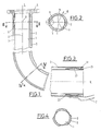
Der Gegenstand der Erfindung wird anhand von in den Figuren dargestellten Ausführungsbeispielen näher erläutert. Es zeigen:
- Fig. 1
- einen schematischen Längsschnitt durch die wesentlichen Teile des Vorrohres außerhalb des erfindungsgemäßen Schiebesitzes,
- Fig. 2
- einen Schnitt entsprechend der Linie II-II in Fig. 1 durch das Vorrohr im motorseitigen Schiebesitzbereich,
- Fig. 3
- einen vergrößerten Längsschnitt durch den katalysatorseitigen Schiebesitz,
- Fig. 4
- einen Querschnitt entsprechend der Linie IV-IV in Fig. 1 durch das Vorrohr in einem Mittelbereich zwischen den beiden Enden, wo das Innenrohr mit dem Mantelrohr fest verbunden, z.B. verschweißt ist,
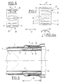
- Fig. 5
- einen Längsschnitt durch das katalysatorseitige Ende des Vorrohres mit einer modifizierten Festlegung der Federringhülse am Innenrohr,
- Fig. 6
- eine schematisierte Schnittdarstellung analog Fig. 5 lediglich der Federringhülse,
- Fig. 6a
- einen Querschnitt entsprechend der Schnittlinie VIa-VIa in Fig. 6,
- Fig. 7
- eine Gesamt-Seitenansicht der Federringhülse,
- Fig. 8
- eine funktionsmäßig der Ausführungsform von Fig. 5 ähnliche Ausführungsform, bei der aber die Federringhülse mit ihren Brückenstegen auf den Außenmantel des Innenrohrs wirkt,
- Fig. 8a
- einen Querschnitt entsprechend der Schnittlinie VIIIa-VIIIa in Fig. 8 durch einen Brückensteg der Federringhülse,
- Fig. 9
- eine Gesamtdarstellung der bei der Ausführungsform nach Fig. 8 verwendeten Federringhülse,
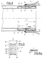
- Fig. 10
- einen Teilausschnitt analog Fig. 5
- Fig. 11
- einen Teilausschnitt analog Fig. 8
- Fig. 1
- 2 shows a schematic longitudinal section through the essential parts of the front pipe outside the sliding seat according to the invention,
- Fig. 2
- 2 shows a section along line II-II in FIG. 1 through the front pipe in the engine-side sliding seat area,
- Fig. 3
- an enlarged longitudinal section through the catalyst-side sliding seat,
- Fig. 4
- 2 shows a cross section along the line IV-IV in FIG. 1 through the front pipe in a central region between the two ends, where the inner pipe is firmly connected, for example welded, to the casing pipe,
- Fig. 5
- 2 shows a longitudinal section through the end of the front tube on the catalytic converter with a modified fixing of the spring ring sleeve on the inner tube,
- Fig. 6
- 5 shows a schematic sectional illustration analogous to FIG. 5 only of the spring ring sleeve,
- Fig. 6a
- 6 shows a cross section corresponding to the section line VIa-VIa in FIG. 6,
- Fig. 7
- an overall side view of the spring ring sleeve,
- Fig. 8
- 5 is an embodiment which is functionally similar to the embodiment of FIG. 5, but in which the spring ring sleeve acts with its bridge webs on the outer jacket of the inner tube,
- Fig. 8a
- 8 shows a cross section corresponding to the section line VIIIa-VIIIa in FIG. 8 through a bridge web of the spring ring sleeve,
- Fig. 9
- 8 shows an overall view of the spring ring sleeve used in the embodiment according to FIG. 8,
- Fig. 10
- a partial section analogous to FIG. 5
- Fig. 11
- a partial section analogous to FIG. 8
Im Bereich beider Enden 4,6 des Vorrohres ist das Innenrohr 1 mit Schiebesitz am Mantelrohr 3 geführt. Eine konstruktive Ausgestaltung der Schiebesitze ist außer in der Längsschnittdarstellung von Fig. 1 besonders deutlich in den Schnittdarstellungen der Fig. 2,3 erkennbar. Wesentlicher Bestandteil dieses Schiebesitzes ist das Vorhandensein von über den Verlauf des Ringspaltes 2 verteilt angeordneten Distanzelementen zwischen Innenrohr 1 und Mantelrohr 3. Diese Distanzelemente schaffen im Schiebesitzbereich eine zusätzliche Winkelbeweglichkeit zwischen Innenrohr 1 und Mantelrohr 3 um einen im Bereich etwa der Rohrachse 8 gedachten Schiebesitz-Mittelpunkt 9.In the area of both ends 4, 6 of the front pipe, the
Gemäß Fig. 1 und 2 sind gleichmäßig über den Umfang verteilt in das Innenrohr 1 in Radialrichtung 10 auf das Mantelrohr 3 vorstehende, sickenartige Ausbeulungen 11 eingeformt. Im Falle des dargestellten Ausführungsbeispieles bilden die Ausbeulungen 11 einen in Rohrlängsrichtung 12 wirksamen Linienkontakt zwischen Innenrohr 1 und Mantelrohr 3. Die insgesamt drei gleichmäßig über den Umfang des Innenrohres 1 verteilten Ausbeulungen 11 können indessen auch so ausgestaltet sein, daß sie lediglich einen Punktkontakt zwischen Innenrohr 1 und Mantelrohr 3 bilden.1 and 2, bead-
Erfindungsgemäße Ausgestaltungen der Distanzelemente sind Gegenstand insbesondere der Fig. 5 bis 11. Die Distanzelemente können dabei an der Konkavseite 12 eines die Querschnittsform etwa einer flachen Rinne aufweisenden Ringkörpers 13-15 anliegen. Mit 13 (Fig. 5) ist ein Innenringkörper bezeichnet, der auf den Außenumfang des Innenrohrs 1 geschweißt ist. Mit 14 ist ein Außenringkörper bezeichnet, der mit der Innenoberfläche des Mantelrohrs 3 verschweißt ist (Fig. 8).Embodiments of the spacer elements according to the invention are the subject of, in particular, FIGS. 5 to 11. The spacer elements can bear against the
Die Ringkörper 13-15 sind mit dem ihren Konkavseiten 12 abgewandten Bodenmantel 16 an einer den Luftringspalt 2 begrenzenden Rohrwand befestigt. Es ist dies bei dem Innenringkörper 13 die Außenwand des Innenrohres 1.The ring bodies 13-15 are fastened with the
Die Ringkörper 13-15 bestehen aus metallischem Werkstoff, insbesondere aus demselben Werkstoff wie das sie tragende Innenrohr 1 oder Mantelrohr 3. Sie weisen die Form eines Zylinders mit an beiden Zylinderenden radial nach innen oder außen abgebogenen Anlageflanschen 44 auf. Die Ringkörper 13-15 sind quer zu ihrer Umfangsrichtung 17 geschlitzt. Ein Ringschlitz 18 ist anhand des Ringkörpers 15 in Fig. 11 dargestellt.The ring bodies 13-15 consist of metallic material, in particular of the same material as the
Die Distanzelemente sind durch dem Rinnenboden 12 abgewandte Umfangsbereiche einer in der Ringrinne 19 einliegenden Federringhülse 20,21 gebildet (Fig. 5 bis 7; 8 und 9).The spacer elements are formed by circumferential regions of the
Bei der Ausführungsform gemäß Fig. 5 bis 7 ist der Innenringkörper 13 mit seinem Bodenmantel 16 am Außenmantel des Innenrohres 1 angeschweißt. Die in seiner Ringrinne 19 einliegende Federringhülse 20 ist eine aus Federstahl bestehende, im wesentlichen zylindrische Manschette mit mehreren über den Manschettenumfang verteilt angeordneten, sich in Axialrichtung 22 zwischen zwei Ringenden 23,24 erstreckenden, radial nach außen ausgewölbten, nach Art von Federlamellen wirksamen Brückenstegen 25, die an der Innenwand des Mantelrohres 3 anliegen, während er mit seinen Ringenden 23,24 auf dem Innenringkörper 13 bzw. am Innenrohr 1 abgestützt ist. Dabei weist der Querschnitt eines Brückensteges 25 die Form etwa eines Kreissegments mit einem Biegeradius 45 auf, der deutlich kleiner ist als der halbe Innendurchmesser des Mantelrohres 3, wobei die Konvexseite des Kreissegments der Innenseite des Mantelrohres 3 zugewandt ist. Dadurch wird das Vorliegen einer einem idealen Punktkontakt am Mantelrohr 3 nahekommenden Konfiguration der Federringhülse 20 am Mantelrohr 3 hergestellt.In the embodiment according to FIGS. 5 to 7, the
Die außerhalb der Brückenstege 25 liegenden Ringenden 23,24 der Federringhülse 20 können ungeschlitzt umfänglich in sich geschlossen sein. Eine andere Ausführungsform sieht vor, daß die Federringhülse 20 durch einen Schlitz 46 geschlitzt ist. Dadurch kann sich die Federringhülse 20 unter dem Einfluß der Erhitzung des Innenrohres 1 umfangsmäßig ungehindert dehnen. Genauso kann die nachstehend beschriebene Federringhülse 21 nach Art des Schlitzes 46 quer zu ihrer Umfangsrichtung geschlitzt sein, auch wenn dies in Fig. 9 im einzelnen nicht dargestellt ist.The ring ends 23, 24 of the
Die lichte Rinnenbreite 26 (Fig. 5) zwischen den Anlageflanschen 44 des Ringkörpers 13 ist größer als die Breite 27 des Federringes 20.The clear channel width 26 (FIG. 5) between the
Bei der Ausführungsform gemäß Fig. 8 ist der Außenringkörper 14 mit seinem Bodenmantel 16 an der Innenseite des Mantelrohres 3 befestigt. Die Federringhülse 21 ist wie die Federringhülse 20 eine aus Federstahl bestehende Manschette mit mehreren über den Manschettenumfang verteilt angeordneten, sich in Axialrichtung 22 zwischen den beiden Ringenden 28,29 erstreckenden, radial nach innen ausgewölbten Brückenstegen 30, die am Innenrohr 1 anliegen, während er mit seinen Ringenden 28,29 auf dem Außenringkörper 14 bzw. am Mantelrohr 1 abgestützt ist. Die Gestalt der Federringhülse 21 ist somit analog der der Federringhülse 20, nur wirken ihre Brückenstege 30 nach innen auf den Umfang des Innenrohres 1, während seine Ringenden 28,29 radial nach außen gegen die Konkavseite 12 des Außenringkörpers 14 bzw. gegen das Mantelrohr 3 wirksam sind.In the embodiment according to FIG. 8, the
Die Ausführungsform der Federringhülse 21 gemäß Fig. 8 bis 9 hat den Vorteil, daß ohne weitere Vorkehrungen von vornherein die Brückenstege 30 zwischen den beiden Ringenden 28,29 die Querschnittsform etwa eines Rechteckes einnehmen, welches mit seiner Langseite etwa tangential am Außenumfang des Innenrohres 1 anliegt (Fig. 8a). Hierbei wird davon ausgegangen, daß die Federringhülse 21 wie die Federringhülse 20 aus einem durch Stanzung und Biegung mit den Brückenstegen 25 bzw. 30 versehenen und durch Verschweißung seiner Schmalenden zu einem umfänglich in sich geschlossenen Ring geformten Blechstreifen aus Federblech hergestellt sind, wobei sich für die Brückenstege 30 selbsttätig die aus Fig. 8a ersichtliche, etwa rechteckige Querschnittsform ergibt, die eine mittig-tangentiale Anlage am Außenumfang des Innenrohres 1 ermöglicht. Demgegenüber sind bei dem Federring 20 (Fig. 6,7) zusätzliche Vorkehrungen erforderlich, um den Brückenstegen 25 die aus Fig. 6a ersichtliche, gewölbte Querschnittsform zu verleihen, die den für beide Federringformen 20,21 idealen, annähernden Punktkontakt im Bereich der Brückenstege 25 bzw. 30 am Gegenrohrmantel sicherstellt.The embodiment of the
Auch die außerhalb der Brückenstege 30 liegenden Ringenden 28,29 der Federringhülse 21 können ungeschlitzt umfänglich in sich geschlossen sein. Auch beim Außenringkörper 14 ist die lichte Rinnenbreite 31 größer als die Breite 32 der Federringhülse 21.The ring ends 28, 29 of the
Die Anlageoberflächen 35 der Ringenden 23,24 der Federringhülse 20 bzw. die Anlageoberflächen 36 der Ringenden 28,29 der Federringhülse 21 weisen eine in Richtung auf die anliegende Rohroberfläche konvex ausgewölbte Querschnittsform auf (Fig. 5 bis 7; 8). Diese Formgestaltung hat auch die Aufgabe, eine möglichst ideale, geringflächige Kontaktsituation zum Ringkörper herzustellen, nämlich im wesentlichen wenigstens einen Linienkontakt.The contact surfaces 35 of the ring ends 23, 24 of the
Die Ausführungsform gemäß Fig. 8 bis 9 mit auf das Innenrohr 1 wirkenden Brückenstegen 30 der Federringhülse 21 hat den weiteren Vorteil, daß das aus dem wertvolleren Werkstoff bestehende Innenrohr 1 eine gegenüber dem Mantelrohr 3 katalysatorseitig kürzere Länge aufweisen kann.The embodiment according to FIGS. 8 to 9 with
Die Fig. 10 und 11 zeigen Ausführungsformen, bei denen die Federringhülsen 20,21 mit dem Innenrohr 1 oder dem Mantelrohr 3 unmittelbar verbunden sind.10 and 11 show embodiments in which the
Die Federringhülsen 20 bzw. 21 sind mit einem ihrer beiden radialen Ringenden 28,29, nämlich im Bereich von deren Anlageoberflächen 35,36 oder mit ihren Brückenstegen 25,30 am anliegenden Innenrohr 1 (Fig. 11) oder am Mantelrohr (3) (Fig. 10) angeschweißt.
Claims (9)
- A feeder pipe with air gap insulation which forms the exhaust pipe between the engine and catalyser of a motor vehicle,a) with an inner pipe (1),b) with an outer pipe (3) supporting the inner pipe (1) and surrounding it while leaving an annular air gap (2), andc) with a sliding seating for guiding the inner pipe (1) on the outer pipe (3),
characterized in thatd) the sliding seating is formed by- distance elements arranged to be distributed over the periphery of the annular air gap (2),- which interspace the inner pipe (1) from the outer pipe (3) and- are subjected to a radial prestressing pressure, in particular, a radial spring pressure,e) that the distance elements are formed by a spring collar (20, 21) lying in the annular air gap (2),- which is provided in a median zone lying between its axial ring ends (23, 24; 28 29) with slots that are distributed over its periphery and extend substantially in the axial direction, and- whose bridging lands (25, 30) extending between neighbouring slots and between the ring ends (23, 24; 28, 29) are radially curved inwards or outwards,f) that the spring collar (20, 21) bears with prestressing with its axial ring ends (23, 24; 28, 29) on one pipe and with its interposed curved bridging lands (25, 30) on the other pipe (1 and 3 respectively), andg) that the spring collar (20, 21) is at one of its axial ring ends (23, 24), or at at least one bridging land (25, 30), connected, in particular welded, to the adjoining pipe (1 or 3 respectively). - A feeder pipe according to claim 1,
characterized in that
the spring collar (20, 21) is at one of its axial ring ends (23, 24), or at least one bridging land (25, 30), joined to the adjoining pipe (1 or 3 respectively) by means of a spot-welded joint. - A feeder pipe according to claim 1,
characterized in that
the spring collar (20, 21) is at one axial ring end (23, 24) joined in its bearing zone to one pipe (1 or 3 respectively) by at least one weld seam extending at least partly in an annular configuration. - A feeder pipe according to one or more of the preceding claims,
characterized in that
at least one bridging land (25) has approximately the cross-sectional shape of a circular segment with a bending radius (45) which is smaller than half the internal diameter, that is to say, the bending radius of the outer pipe (3), and that the bridging land (25) bears on the outer pipe (3) with the convex side of its cross-sectional shape. - A feeder pipe according to one of claims 1 to 4,
characterized in that
the axial ring ends (23, 24) of the spring collar (20, 21) lying outside the bridging lands (25) are peripherally closed in themselves without any slots. - A feeder pipe according to one of claims 1 to 4,
characterized in that
the ring ends (23, 24; 28, 29) of the spring collar (20, 21) are slotted in the continuation of one slot (46). - A feeder pipe according to one or more of the preceding claims,
characterized by
a cross-sectional shape, curving in the direction towards the adjacent wall of one pipe (1 or 3 respectively) of the bearing sides (35, 36) of the ring ends (23, 24; 28, 29) of the spring collar (20, 21). - A feeder pipe according to one or more of the preceding claims,
characterized in that
the sliding seating is arranged at its end (6) on the catalyser side and that the catalyser housing (7) is there welded to the outer circumference of its outer pipe (3). - A feeder pipe according to one or more of the preceding claims,
characterized in that
the inner pipe (1) is secured between the two pipe ends (4, 6) on the outer pipe (3) and is carried at both ends on the outer pipe (3) by a sliding seating.
Applications Claiming Priority (2)
| Application Number | Priority Date | Filing Date | Title |
|---|---|---|---|
| DE9102926U DE9102926U1 (en) | 1991-03-12 | 1991-03-12 | |
| DE9102926U | 1991-03-12 |
Publications (2)
| Publication Number | Publication Date |
|---|---|
| EP0508145A1 EP0508145A1 (en) | 1992-10-14 |
| EP0508145B1 true EP0508145B1 (en) | 1994-12-07 |
Family
ID=6865144
Family Applications (2)
| Application Number | Title | Priority Date | Filing Date |
|---|---|---|---|
| EP92104145A Expired - Lifetime EP0503580B1 (en) | 1991-03-12 | 1992-03-11 | Exhaust pipe with air gap insulation |
| EP92104258A Expired - Lifetime EP0508145B1 (en) | 1991-03-12 | 1992-03-12 | Exhaust pipe with air gap insulation |
Family Applications Before (1)
| Application Number | Title | Priority Date | Filing Date |
|---|---|---|---|
| EP92104145A Expired - Lifetime EP0503580B1 (en) | 1991-03-12 | 1992-03-11 | Exhaust pipe with air gap insulation |
Country Status (3)
| Country | Link |
|---|---|
| EP (2) | EP0503580B1 (en) |
| DE (3) | DE9102926U1 (en) |
| ES (1) | ES2075503T3 (en) |
Cited By (1)
| Publication number | Priority date | Publication date | Assignee | Title |
|---|---|---|---|---|
| EP0662564B2 (en) † | 1994-01-07 | 2001-09-26 | J. Eberspächer GmbH & Co. | Air gap insulation exhaust pipe and method of construction |
Families Citing this family (19)
| Publication number | Priority date | Publication date | Assignee | Title |
|---|---|---|---|---|
| DE9102926U1 (en) * | 1991-03-12 | 1991-08-08 | Leistritz Ag & Co Abgastechnik, 8510 Fuerth, De | |
| DE4134466A1 (en) * | 1991-10-18 | 1993-04-22 | Eberspaecher J | DOUBLE-WALLED AIR-INSULATED TUBE FOR EXHAUST SYSTEMS IN VEHICLES |
| DE4229467A1 (en) * | 1992-09-03 | 1994-03-10 | Mtu Friedrichshafen Gmbh | Storage device for the exhaust manifold of an internal combustion engine |
| DE19606003A1 (en) * | 1996-02-17 | 1997-06-12 | Daimler Benz Ag | Pipe connector with sliding seat |
| DE19722037A1 (en) * | 1997-05-27 | 1998-12-03 | Hecralmat Fa | Heat shield with sound insulation |
| DE19917604C5 (en) * | 1998-04-20 | 2009-09-10 | Honda Giken Kogyo K.K. | Heat insulated exhaust manifold |
| EP1091101B1 (en) * | 1999-10-08 | 2004-12-29 | Kabushiki Kaisha Yutaka Giken | Exhaust pipe assembly of two-passage construction |
| JP2002155720A (en) * | 2000-11-20 | 2002-05-31 | Yamaha Motor Co Ltd | Union structure of blow-by gas reducing device |
| DE10105841C2 (en) * | 2001-02-07 | 2002-12-12 | Benteler Automobiltechnik Gmbh | Exhaust pipe with air gap insulation for an internal combustion engine |
| DE10357344A1 (en) * | 2003-12-09 | 2005-07-14 | Daimlerchrysler Ag | Air gap insulated exhaust pipe, and method for its production |
| DE102009059684A1 (en) | 2009-12-19 | 2011-06-22 | J. Eberspächer GmbH & Co. KG, 73730 | Exhaust gas treatment device |
| DE102010040249A1 (en) * | 2010-09-03 | 2012-03-08 | Man Diesel & Turbo Se | Double walled pipe |
| DE102011012595A1 (en) * | 2011-02-28 | 2012-08-30 | Faurecia Emissions Control Technologies, Germany Gmbh | Air gap insulated exhaust pipe e.g. exhaust gas manifold has support plate that is secured between inner and outer walls which are slidingly fitted with inlet portion and outlet portion relative to each other |
| DE102012021063A1 (en) * | 2012-10-20 | 2014-04-24 | Daimler Ag | Air-gap insulated exhaust pipe unit of combustion engine for motor car, has pipe section in sliding seat section, which comprises projection that extends into gap, so that gap in section of sliding seat section is narrowed radially |
| DE102014018127A1 (en) | 2014-12-06 | 2016-06-09 | Daimler Ag | Connecting arrangement of an air gap-insulated exhaust gas guide element to a further exhaust gas guide element |
| DE102015112560A1 (en) * | 2015-07-30 | 2017-02-02 | Elringklinger Ag | sealing device |
| CN108240512A (en) * | 2016-12-26 | 2018-07-03 | 天津市科瑞燃气设备有限公司 | A kind of gas pipeline air inlet pipe |
| EP3599405A1 (en) * | 2018-07-25 | 2020-01-29 | Holter Regelarmaturen GmbH & Co. KG | Pipeline for passing a hot fluid |
| CN111895224B (en) * | 2020-07-10 | 2022-02-11 | 中国兵器工业第五九研究所 | Modularization heat preservation shell structure |
Citations (1)
| Publication number | Priority date | Publication date | Assignee | Title |
|---|---|---|---|---|
| EP0503580A1 (en) * | 1991-03-12 | 1992-09-16 | LEISTRITZ AG & CO. Abgastechnik | Exhaust pipe with air gap insulation |
Family Cites Families (7)
| Publication number | Priority date | Publication date | Assignee | Title |
|---|---|---|---|---|
| FR1394743A (en) * | 1963-09-16 | 1965-04-09 | Petrole Chimie Soc | Elastic insulating collars for pipelines |
| DE2452556A1 (en) * | 1974-11-06 | 1976-05-13 | Audi Nsu Auto Union Ag | IC engine exhaust after-burner - has exhaust pipes from different cylinder pair arranged to have wall in common |
| US4185463A (en) * | 1976-05-18 | 1980-01-29 | Toyota Jibosha Kogyo Kabushiki Kaisha | Exhaust double pipe of an internal combustion engine |
| US4250927A (en) * | 1979-08-24 | 1981-02-17 | Piper Aircraft Corporation | Duct spacer clip and duct assembly |
| DE3017574C2 (en) * | 1980-05-08 | 1985-06-05 | Wieland-Werke Ag, 7900 Ulm | Spacers for coaxial heat exchangers |
| US4607665A (en) * | 1985-05-20 | 1986-08-26 | Marco Manufacturing, Inc. | Pipe spacer |
| DE8912161U1 (en) * | 1989-10-12 | 1991-02-07 | Zeuna-Staerker Gmbh & Co Kg, 8900 Augsburg, De |
-
1991
- 1991-03-12 DE DE9102926U patent/DE9102926U1/de not_active Expired - Lifetime
-
1992
- 1992-03-11 EP EP92104145A patent/EP0503580B1/en not_active Expired - Lifetime
- 1992-03-11 DE DE59202891T patent/DE59202891D1/en not_active Expired - Fee Related
- 1992-03-11 ES ES92104145T patent/ES2075503T3/en not_active Expired - Lifetime
- 1992-03-12 EP EP92104258A patent/EP0508145B1/en not_active Expired - Lifetime
- 1992-03-12 DE DE59200885T patent/DE59200885D1/en not_active Expired - Fee Related
Patent Citations (1)
| Publication number | Priority date | Publication date | Assignee | Title |
|---|---|---|---|---|
| EP0503580A1 (en) * | 1991-03-12 | 1992-09-16 | LEISTRITZ AG & CO. Abgastechnik | Exhaust pipe with air gap insulation |
Cited By (1)
| Publication number | Priority date | Publication date | Assignee | Title |
|---|---|---|---|---|
| EP0662564B2 (en) † | 1994-01-07 | 2001-09-26 | J. Eberspächer GmbH & Co. | Air gap insulation exhaust pipe and method of construction |
Also Published As
| Publication number | Publication date |
|---|---|
| DE59200885D1 (en) | 1995-01-19 |
| DE9102926U1 (en) | 1991-08-08 |
| DE59202891D1 (en) | 1995-08-24 |
| ES2075503T3 (en) | 1995-10-01 |
| EP0508145A1 (en) | 1992-10-14 |
| EP0503580B1 (en) | 1995-07-19 |
| EP0503580A1 (en) | 1992-09-16 |
Similar Documents
| Publication | Publication Date | Title |
|---|---|---|
| EP0508145B1 (en) | Exhaust pipe with air gap insulation | |
| EP0212331B1 (en) | Connection of two pipes of a hot medium conduit | |
| EP1887194B1 (en) | Exhaust gas purification device | |
| DE102008052552B4 (en) | Turbine housing and method for its production | |
| EP0582985B1 (en) | Exhaust manifold | |
| EP0683851B1 (en) | Metallic honeycomb structure supported in an inner and an outer casing tube, especially a catalyst support | |
| EP0580963B1 (en) | Articulated pipe | |
| EP0797039A2 (en) | Pipe member having a metal bellows | |
| EP0537603B1 (en) | Double-walled air-insulated pipe for exhaust installations in vehicles | |
| EP3365562B1 (en) | Plate-like component with a fastening device reaching through the plate-like component | |
| EP0881422A1 (en) | Conduit element with at least two bellows and an intermediate pipe connecting them | |
| EP0681097B1 (en) | Flexible connecting element for tubular parts | |
| EP0208128A1 (en) | Articulated connection of pipe parts, particularly in exhaust gas conduits of motor vehicles | |
| EP1048881B1 (en) | Refrigerant line for air conditioners | |
| EP1149992A1 (en) | Exhaust assembly for an exhaust gas system, especially exhaust gas catalyst of modular construction for a motor vehicle | |
| EP0573764B1 (en) | Articulated connection of pipe parts, particularly in exhaust systems of motor vehicles | |
| EP0398086B1 (en) | Connector for two pipes of a hot medium conduit | |
| EP0747582A2 (en) | Decoupling element for vibrations in pipes | |
| EP0983425B1 (en) | System for avoiding mechanical vibrations | |
| EP1571396B1 (en) | Sealing body for gas turbine combustor | |
| EP0665366A1 (en) | Double wall exhaust pipe | |
| EP1859132B1 (en) | Housing for a waste gas treatment component comprising a reinforced covering | |
| DE4202079C2 (en) | Exhaust system for internal combustion engines | |
| DE3526481A1 (en) | Connection of two pipe ends by means of a corrugated pipe | |
| EP3179066B1 (en) | Silencer and manufacturing method |
Legal Events
| Date | Code | Title | Description |
|---|---|---|---|
| PUAI | Public reference made under article 153(3) epc to a published international application that has entered the european phase |
Free format text: ORIGINAL CODE: 0009012 |
|
| AK | Designated contracting states |
Kind code of ref document: A1 Designated state(s): AT BE CH DE DK ES FR GB GR IT LI LU MC NL PT SE |
|
| RBV | Designated contracting states (corrected) |
Designated state(s): BE DE DK ES FR GB GR IT LU NL PT SE |
|
| 17P | Request for examination filed |
Effective date: 19921125 |
|
| 17Q | First examination report despatched |
Effective date: 19930113 |
|
| GRAA | (expected) grant |
Free format text: ORIGINAL CODE: 0009210 |
|
| AK | Designated contracting states |
Kind code of ref document: B1 Designated state(s): BE DE DK ES FR GB GR IT LU NL PT SE |
|
| PG25 | Lapsed in a contracting state [announced via postgrant information from national office to epo] |
Ref country code: IT Free format text: LAPSE BECAUSE OF FAILURE TO SUBMIT A TRANSLATION OF THE DESCRIPTION OR TO PAY THE FEE WITHIN THE PRE;WARNING: LAPSES OF ITALIAN PATENTS WITH EFFECTIVE DATE BEFORE 2007 MAY HAVE OCCURRED AT ANY TIME BEFORE 2007. THE CORRECT EFFECTIVE DATE MAY BE DIFFERENT FROM THE ONE RECORDED.SCRIBED TIME-LIMIT Effective date: 19941207 Ref country code: GR Free format text: LAPSE BECAUSE OF FAILURE TO SUBMIT A TRANSLATION OF THE DESCRIPTION OR TO PAY THE FEE WITHIN THE PRESCRIBED TIME-LIMIT Effective date: 19941207 Ref country code: NL Effective date: 19941207 Ref country code: ES Free format text: THE PATENT HAS BEEN ANNULLED BY A DECISION OF A NATIONAL AUTHORITY Effective date: 19941207 Ref country code: DK Effective date: 19941207 Ref country code: GB Effective date: 19941207 Ref country code: BE Effective date: 19941207 |
|
| REF | Corresponds to: |
Ref document number: 59200885 Country of ref document: DE Date of ref document: 19950119 |
|
| PG25 | Lapsed in a contracting state [announced via postgrant information from national office to epo] |
Ref country code: PT Effective date: 19950307 Ref country code: SE Effective date: 19950307 |
|
| ET | Fr: translation filed | ||
| PG25 | Lapsed in a contracting state [announced via postgrant information from national office to epo] |
Ref country code: LU Free format text: LAPSE BECAUSE OF NON-PAYMENT OF DUE FEES Effective date: 19950331 |
|
| NLV1 | Nl: lapsed or annulled due to failure to fulfill the requirements of art. 29p and 29m of the patents act | ||
| GBV | Gb: ep patent (uk) treated as always having been void in accordance with gb section 77(7)/1977 [no translation filed] |
Effective date: 19941207 |
|
| PLBE | No opposition filed within time limit |
Free format text: ORIGINAL CODE: 0009261 |
|
| STAA | Information on the status of an ep patent application or granted ep patent |
Free format text: STATUS: NO OPPOSITION FILED WITHIN TIME LIMIT |
|
| 26N | No opposition filed | ||
| PGFP | Annual fee paid to national office [announced via postgrant information from national office to epo] |
Ref country code: FR Payment date: 19980317 Year of fee payment: 7 |
|
| PGFP | Annual fee paid to national office [announced via postgrant information from national office to epo] |
Ref country code: DE Payment date: 19980408 Year of fee payment: 7 |
|
| PG25 | Lapsed in a contracting state [announced via postgrant information from national office to epo] |
Ref country code: FR Free format text: LAPSE BECAUSE OF NON-PAYMENT OF DUE FEES Effective date: 19991130 |
|
| REG | Reference to a national code |
Ref country code: FR Ref legal event code: ST |
|
| PG25 | Lapsed in a contracting state [announced via postgrant information from national office to epo] |
Ref country code: DE Free format text: LAPSE BECAUSE OF NON-PAYMENT OF DUE FEES Effective date: 20000101 |