EP0681097B1 - Flexible connecting element for tubular parts - Google Patents
Flexible connecting element for tubular parts Download PDFInfo
- Publication number
- EP0681097B1 EP0681097B1 EP95101543A EP95101543A EP0681097B1 EP 0681097 B1 EP0681097 B1 EP 0681097B1 EP 95101543 A EP95101543 A EP 95101543A EP 95101543 A EP95101543 A EP 95101543A EP 0681097 B1 EP0681097 B1 EP 0681097B1
- Authority
- EP
- European Patent Office
- Prior art keywords
- support
- connecting element
- element according
- spring element
- cushion
- Prior art date
- Legal status (The legal status is an assumption and is not a legal conclusion. Google has not performed a legal analysis and makes no representation as to the accuracy of the status listed.)
- Expired - Lifetime
Links
Images


Classifications
-
- F—MECHANICAL ENGINEERING; LIGHTING; HEATING; WEAPONS; BLASTING
- F01—MACHINES OR ENGINES IN GENERAL; ENGINE PLANTS IN GENERAL; STEAM ENGINES
- F01N—GAS-FLOW SILENCERS OR EXHAUST APPARATUS FOR MACHINES OR ENGINES IN GENERAL; GAS-FLOW SILENCERS OR EXHAUST APPARATUS FOR INTERNAL COMBUSTION ENGINES
- F01N13/00—Exhaust or silencing apparatus characterised by constructional features ; Exhaust or silencing apparatus, or parts thereof, having pertinent characteristics not provided for in, or of interest apart from, groups F01N1/00 - F01N5/00, F01N9/00, F01N11/00
- F01N13/18—Construction facilitating manufacture, assembly, or disassembly
- F01N13/1805—Fixing exhaust manifolds, exhaust pipes or pipe sections to each other, to engine or to vehicle body
- F01N13/1811—Fixing exhaust manifolds, exhaust pipes or pipe sections to each other, to engine or to vehicle body with means permitting relative movement, e.g. compensation of thermal expansion or vibration
-
- F—MECHANICAL ENGINEERING; LIGHTING; HEATING; WEAPONS; BLASTING
- F16—ENGINEERING ELEMENTS AND UNITS; GENERAL MEASURES FOR PRODUCING AND MAINTAINING EFFECTIVE FUNCTIONING OF MACHINES OR INSTALLATIONS; THERMAL INSULATION IN GENERAL
- F16L—PIPES; JOINTS OR FITTINGS FOR PIPES; SUPPORTS FOR PIPES, CABLES OR PROTECTIVE TUBING; MEANS FOR THERMAL INSULATION IN GENERAL
- F16L27/00—Adjustable joints, Joints allowing movement
- F16L27/10—Adjustable joints, Joints allowing movement comprising a flexible connection only, e.g. for damping vibrations
- F16L27/1021—Adjustable joints, Joints allowing movement comprising a flexible connection only, e.g. for damping vibrations comprising an intermediate resilient element, e.g. a ring
-
- F—MECHANICAL ENGINEERING; LIGHTING; HEATING; WEAPONS; BLASTING
- F16—ENGINEERING ELEMENTS AND UNITS; GENERAL MEASURES FOR PRODUCING AND MAINTAINING EFFECTIVE FUNCTIONING OF MACHINES OR INSTALLATIONS; THERMAL INSULATION IN GENERAL
- F16L—PIPES; JOINTS OR FITTINGS FOR PIPES; SUPPORTS FOR PIPES, CABLES OR PROTECTIVE TUBING; MEANS FOR THERMAL INSULATION IN GENERAL
- F16L27/00—Adjustable joints, Joints allowing movement
- F16L27/10—Adjustable joints, Joints allowing movement comprising a flexible connection only, e.g. for damping vibrations
- F16L27/107—Adjustable joints, Joints allowing movement comprising a flexible connection only, e.g. for damping vibrations the ends of the pipe being interconnected by a flexible sleeve
- F16L27/11—Adjustable joints, Joints allowing movement comprising a flexible connection only, e.g. for damping vibrations the ends of the pipe being interconnected by a flexible sleeve the sleeve having the form of a bellows with multiple corrugations
-
- F—MECHANICAL ENGINEERING; LIGHTING; HEATING; WEAPONS; BLASTING
- F16—ENGINEERING ELEMENTS AND UNITS; GENERAL MEASURES FOR PRODUCING AND MAINTAINING EFFECTIVE FUNCTIONING OF MACHINES OR INSTALLATIONS; THERMAL INSULATION IN GENERAL
- F16L—PIPES; JOINTS OR FITTINGS FOR PIPES; SUPPORTS FOR PIPES, CABLES OR PROTECTIVE TUBING; MEANS FOR THERMAL INSULATION IN GENERAL
- F16L51/00—Expansion-compensation arrangements for pipe-lines
- F16L51/02—Expansion-compensation arrangements for pipe-lines making use of bellows or an expansible folded or corrugated tube
- F16L51/025—Expansion-compensation arrangements for pipe-lines making use of bellows or an expansible folded or corrugated tube with several corrugations
Definitions
- the invention relates to an articulated connecting element for pipe parts, in particular pipe parts of exhaust pipes of internal combustion engines of motor vehicles, consisting of at least one flexible pipe element, at least indirectly connected tightly to the pipe parts, and a support pipe arranged inside or outside the pipe element and at least indirectly connected to the pipe parts the at least one end is connected to the pipe part adjacent to it via at least one support pad with damped resilient properties and a support part surrounding it in an angularly movable mutually supporting connection, the support pad being on both sides in the axial and radial direction against the support pipe and / or the support part is in plant.
- Such articulated connecting elements are used between two generally aligned pipe parts of pipelines in order to permit angular movements and also axial movements between the pipe parts to a small extent, as well as a mutual decoupling with regard to the transmission of vibrations and noise between the pipe parts surrender.
- Coming field of application are the exhaust pipes of internal combustion engines in motor vehicles, to which reference is essentially made below, without thereby restricting the scope of the subject matter of the invention.
- FIG. 1 An articulated connecting element of the type mentioned is known from EP-PS-0 208 128. From this it can be seen (FIG. 1) that the tube parts can be smooth tubes or their ends, but the use of connecting flanges etc. is just as well possible.
- the cross section of the pipe parts is generally circular and coaxial to the correspondingly circular line element. However, other cross sections are also conceivable, for example an oval cross section of the pipe parts with a correspondingly adapted cross section of the line element.
- An oval or polygonal cross-section of the line element can also be used, for example, if the exhaust system is designed with two or more passages, the flow channels thus formed being tightly surrounded by a flexible line element (FIGS. 1 and 10 of EP-PS-0 208 128 ).
- the shape of a single- or multi-layer corrugated tube, bellows, tightly wound hose or the like can be considered, the choice of material depending on the given requirements.
- Metal is used in exhaust pipe systems of motor vehicles to form the line element.
- one articulation point is often sufficient.
- two articulation points, one at each end of the support tube can be designed in the same way as one another, in order to place the resulting articulation point as far as possible in the longitudinal center of the axis of the line element and thus to load it as little as possible.
- a plurality of connecting elements of the type described above can also be arranged one behind the other. Examples of this are shown in EP-A-0 580 963.
- the support tube in connection with the formation of the hinge point, can be arranged within the line element, as is the case with the objects of the previously published publications happen.
- the support tube outside the line element, as is shown by the embodiment according to FIG. 3 of DE-GM 93 01 772.
- the support part is on the outside and connected to the adjacent tube part, while in the latter case the support part is only connected to the support tube, while the support cushion is seated inside on a tube piece connected to the adjacent tube part.
- the support pad of the respective articulation point can be a closed ring which surrounds the support tube or is inserted into the support part.
- ring segments distributed over the circumference or other part shapes can also be used if the construction is adapted, in particular in order not to make the joint too stiff or to exert a certain influence on the joint stiffness.
- it is within this framework for example, to arrange two annular support pads or two such ring segments axially next to one another, for example the support pad rings being able to be kept at an axial distance by a radial unfolding of the support tube.
- the support pad or pads as a relatively rigid component within the articulation point, permit only a slight axial mobility of the parts supported against one another via the pad.
- the material of the support pad (s) settles during the joint work, which results in a loose or at least a change in the suspension characteristic of the support pad (s).
- the latter is additionally influenced by wear of the parts that are movable relative to one another within the joint. This then goes hand in hand with a reduction in the desired degree of damping.
- EP-A-0 575 727 provides for axially prestressing the support pad or pads when assembling the respective articulation point by the parts carrying the support pad or pads.
- this measure has not proven to be sufficient, since the setting behavior mentioned occurs again and wear-related changes cannot be eliminated.
- the object of the invention is therefore to modify or add to the design of the articulation point for an articulated connecting element of the type mentioned in such a way that both the axial mobility of the articulation point is increased and the setting behavior and wear in terms of its effects have been countered.
- the support pad by at least one, biased spring element is pressurized, wherein the support pad can be pressurized in the axial direction and / or radial direction of the articulated connection.
- the support pad and thus the joint location within the path of the spring element is axially movable or axially displaceable, which can be matched to the respective requirements by selecting and dimensioning the spring element.
- the setting behavior of the support pad and its wear-related change in shape can now be compensated for by the spring element, without this resulting in any significant change in the spring characteristic.
- the spring element can be arranged on the side of the support pad facing the line element.
- the spring element is arranged on the side of the support cushion facing away from the line element and is in axial contact with the support tube and / or the support part on the side facing away from the support cushion. This arrangement has the advantage that the hinge point formed by the support cushion sits as close as possible to the line element, which benefits the life of the line element.
- the spring element can be placed between them in order to be in contact with one of the support cushions on each side, that is to say to operate both support cushions with regard to the setting and wear behavior.
- bellows-like elements, coil springs or the like can be used.
- the radial unfolding of the support tube mentioned at the beginning can also be designed as a spring element.
- the spring element is formed by at least one plate spring washer made of metal. This only takes up a small amount of space and, on the other hand, provides sufficient axial mobility.
- the spring element is formed by at least one radially or circumferentially corrugated washer. Such a design also takes up little space and, on the other hand, provides the necessary control variables.
- the spring element is in contact with an intermediate washer, at least on the side facing the support pad.
- the surface of the support pad facing the spring element is adapted to, or corresponds to, the adjacent contour of the spring element.
- Figure 1 shows two pipe parts 1, 2, the coaxial ends of which are directed towards one another. Between the pipe parts 1, 2, an articulated connecting element, generally designated 3, is inserted as a coupling, and the exhaust gas can in principle flow through it in both directions.
- an articulated connecting element generally designated 3
- the exhaust gas can in principle flow through it in both directions.
- the connecting element consists essentially of an annular corrugated metal bellows 4, which is placed with its cylindrical end 5 on the free end 6 there of a support tube 7 and held on the end 6 by an end ring 8. This unit is welded at 9 to the end of the inserted pipe part 1.
- the other end of the metal bellows 4 is welded to an annular support part 10, which is attached to the end of the pipe part 2 with an inserted and welded-on connection part 11 and is welded to it at 12.
- the support tube 7 protrudes axially into the support part 10, where it forms an annular chamber together with the support part 10 by means of a circumferential bead 13 and a terminal flare 14, which is axially on the part of the support part 10 through its flange 15 and is limited on the side of the pipe part 2 by the connector 11 used.
- two circular support pads 16, 17 are inserted with a mutual axial distance, the support pad 16 axially against the Support flange 15 and the bead 13 and the support pad 17 axially against the flange 14 and the connecting part 11.
- the plate springs 18 Due to the presence of the plate springs 18, there is a limited mutual axial mobility of the tube parts 1, 2, the plate springs 18 at the same time also compensating for the setting of the support pads 16, 17 and a wear-related slack within the joint. Through a suitable selection of the telescopic springs 18, the articulation point can be given the necessary resistance with respect to the mutual axial movement of the tube parts 1 and 2.
- the intermediate washers 19 are provided so that the force exerted by the telescopic springs 18 on the support pads 16, 17 flows into them as widely as possible.
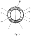
- Figures 2 and 3 show a variant of the object according to Figure 1, wherein the same parts with the same Numbers are provided and are not described again in detail.
- retaining brackets 22, 23 are inserted into the support part 10 and connected to it by spot welding, which are in contact with the support pads 20, 21 with radially inwardly directed webs 24 to 27.
- these holding brackets 22, 23 are reduced in their width perpendicular to the plane of the drawing in FIG. 3 in such a way that they do not hinder the operation of the plate spring 18 resting on the support pads 20, 21.
- the pivot point of the articulation point is as far as possible in the direction placed on the metal bellows.
Description
Die Erfindung betrifft ein gelenkiges Verbindungselement für Rohrteile, insbesondere Rohrteile von Abgasleitungen der Verbrennungsmotore von Kraftfahrzeugen, bestehend aus mindestens einem flexiblen, wenigstens mittelbar mit den Rohrteilen dicht verbundenen Leitungselement sowie einem innerhalb oder außerhalb des Leitungselementes angeordneten, mit den Rohrteilen zumindest mittelbar verbundenen Stützrohr, von dem wenigstens ein Ende mit dem diesem benachbarten Rohrteil über mindestens ein Stützpolster mit gedämpft federnden Eigenschaften sowie ein dieses umschließendes Stützteil in angular zueinander beweglich geführter, gegenseitig tragender Verbindung steht, wobei das Stützpolster beidseits in Axial- und Radialrichtung gegen das Stützrohr und/oder das Stützteil in Anlage ist.The invention relates to an articulated connecting element for pipe parts, in particular pipe parts of exhaust pipes of internal combustion engines of motor vehicles, consisting of at least one flexible pipe element, at least indirectly connected tightly to the pipe parts, and a support pipe arranged inside or outside the pipe element and at least indirectly connected to the pipe parts the at least one end is connected to the pipe part adjacent to it via at least one support pad with damped resilient properties and a support part surrounding it in an angularly movable mutually supporting connection, the support pad being on both sides in the axial and radial direction against the support pipe and / or the support part is in plant.
Derartige gelenkige Verbindungselemente werden zwischen zwei in der Regel im wesentlichen miteinander fluchtende Rohrteile von Rohrleitungen eingesetzt, um Angularbewegungen und auch Axialbewegungen zwischen den Rohrteilen in wenn auch oft nur in geringem Maße zuzulassen sowie eine gegenseitige Abkopplung bezüglich der Übertragung von Schwingungen und Geräuschen zwischen den Rohrteilen zu ergeben. Ein hier besonders in Frage kommendes Anwendungsgebiet sind die Abgasleitungen von Verbrennungsmotoren bei Kraftfahrzeugen, auf die nachfolgend im wesentlichen Bezug genommen wird, ohne damit den Anwendungsbereich des Gegenstandes der Erfindung zu beschränken.Such articulated connecting elements are used between two generally aligned pipe parts of pipelines in order to permit angular movements and also axial movements between the pipe parts to a small extent, as well as a mutual decoupling with regard to the transmission of vibrations and noise between the pipe parts surrender. One particularly in question here Coming field of application are the exhaust pipes of internal combustion engines in motor vehicles, to which reference is essentially made below, without thereby restricting the scope of the subject matter of the invention.
Ein gelenkiges Verbindungselement der eingangs genannten Gattung ist durch die EP-PS-0 208 128 bekannt. Daraus ist ersichtlich (Figur 1), daß die Rohrteile Glattrohre bzw. deren Enden sein können, dafür aber genausogut die Verwendung von Anschlußflanschen etc. in Frage kommt. Der Querschnitt der Rohrteile ist in der Regel kreisförmig und koaxial zum entsprechend ebenfalls kreisförmigen Leitungselement. Es sind jedoch auch andere Querschnitte denkbar, beispielsweise ein ovaler Querschnitt der Rohrteile mit entsprechend angepaßtem Querschnitt des Leitungselementes. Es kommt auch ein ovaler oder polygonaler Querschnitt des Leitungselementes in Frage beispielsweise dann, wenn die Abgasanlage zweiflutig oder mehrflutig ausgebildet ist, wobei dann die so gebildeten Strömungskanäle durch ein flexibles Leitungselement dicht umgeben werden (Figur 1 und 10 der EP-PS-0 208 128).An articulated connecting element of the type mentioned is known from EP-PS-0 208 128. From this it can be seen (FIG. 1) that the tube parts can be smooth tubes or their ends, but the use of connecting flanges etc. is just as well possible. The cross section of the pipe parts is generally circular and coaxial to the correspondingly circular line element. However, other cross sections are also conceivable, for example an oval cross section of the pipe parts with a correspondingly adapted cross section of the line element. An oval or polygonal cross-section of the line element can also be used, for example, if the exhaust system is designed with two or more passages, the flow channels thus formed being tightly surrounded by a flexible line element (FIGS. 1 and 10 of EP-PS-0 208 128 ).
Was das flexible Leitungselement betrifft, so kommen für dieses die Form eines ein- oder mehrlagigen Wellrohres, Balges, dichtgewickelten Schlauches oder dergleichen in Frage, wobei sich die Materialwahl nach den gegebenen Anforderungen richtet. Bei Abgasleitungen von Kraftfahrzeugen findet Metall zur Ausbildung des Leitungselementes Verwendung.As far as the flexible pipe element is concerned, the shape of a single- or multi-layer corrugated tube, bellows, tightly wound hose or the like can be considered, the choice of material depending on the given requirements. Metal is used in exhaust pipe systems of motor vehicles to form the line element.
Was die Zahl der Gelenkstellen des gattungsmäßigen Verbindungselementes betrifft, so ist vielfach eine Gelenkstelle ausreichend. Es können jedoch auch zwei Gelenkstellen, eine am jeden Ende des Stützrohres in untereinander gleicher Weise ausgebildet sein, um den resultierenden Gelenkpunkt möglichst in die Längsmitte der Achse des Leitungselementes zu legen und dieses damit geringstmöglich zu belasten. Um eine weitere Vergrößerung insbesondere der Angularbeweglichkeit zweier aufeinander zugerichteter Rohrteile zu erreichen, können auch mehrere Verbindungselemente der vorbeschriebenen Art hintereinander angeordnet werden. Beispiele hierfür zeigt die EP-A-0 580 963.As far as the number of articulation points of the generic connecting element is concerned, one articulation point is often sufficient. However, two articulation points, one at each end of the support tube, can be designed in the same way as one another, in order to place the resulting articulation point as far as possible in the longitudinal center of the axis of the line element and thus to load it as little as possible. In order to achieve a further enlargement, in particular of the angular mobility of two pipe parts facing one another, a plurality of connecting elements of the type described above can also be arranged one behind the other. Examples of this are shown in EP-A-0 580 963.
Sind bei durch das Verbindungselement aneinandergekoppelten Rohrteilen gegenseitige Torsionsbewegungen zu erwarten, die von einem Leitungselement der hier in Frage kommenden Art nur schlecht abgestützt werden können, so besteht bei einem Verbindungselement der eingangs genannten Gattung die Möglichkeit, das jeweilige Stützrohrende im Bereich der durch das Stützpolster gebildeten Gelenkstelle mechanisch gegenüber dem benachbarten Rohrteil bzw. Stützteil in Umfangsrichtung beispielsweise durch eine formschlüssige Verbindung abzustützen, die die Gelenkarbeit des Verbindungselementes nicht beeinträchtigt. Beispiele hierfür sind der DE-A-42 19 241 zu entnehmen.If mutual torsional movements are to be expected in the case of pipe parts coupled to one another by the connecting element, which can only be supported poorly by a line element of the type in question here, then there is the possibility in the case of a connecting element of the type mentioned in the introduction, the respective support pipe end in the region of the support cushion Mechanically support the joint point in relation to the adjacent pipe part or support part in the circumferential direction, for example by means of a positive connection which does not impair the articulation of the connecting element. Examples of this can be found in DE-A-42 19 241.
Was die Ausbildung und Anordnung des Stützrohres in Verbindung mit der Bildung der Gelenkstelle betrifft, so kann das Stützrohr innerhalb des Leitungselementes angeordnet sein, wie dies bei den Gegenständen der bisher genannten Vorveröffentlichungen geschieht. Es besteht jedoch auch die Möglichkeit, das Stützrohr nach außerhalb des Leitungselementes zu legen, wie dies die Ausführungsform gemäß Figur 3 des DE-GM 93 01 772 zeigt. In einem Falle ist dabei das Stützteil außenliegend und mit dem benachbarten Rohrteil verbunden, während im letztgenannten Falle das Stützteil nur mit dem Stützrohr verbunden ist, während das Stützpolster innen auf einem mit dem benachbarten Rohrteil verbundenen Rohrstück sitzt.As for the design and arrangement of the support tube in connection with the formation of the hinge point, the support tube can be arranged within the line element, as is the case with the objects of the previously published publications happen. However, there is also the possibility of placing the support tube outside the line element, as is shown by the embodiment according to FIG. 3 of DE-GM 93 01 772. In one case, the support part is on the outside and connected to the adjacent tube part, while in the latter case the support part is only connected to the support tube, while the support cushion is seated inside on a tube piece connected to the adjacent tube part.
Hinsichtlich der Ausbildung des Stützpolsters sind diese aus einem Geflecht, Gewirke, Gestricke oder dergleichen gepreßte Teile, die auch zur Abdichtung mit Graphit imprägniert sein können, wobei als Material in der Regel Metalldraht Verwendung findet, je nach Temperatur- bzw. sonstiger Belastung jedoch auch andere Materialien in Frage kommen. Das Stützpolster der jeweiligen Gelenkstelle kann ein das Stützrohr umschließender bzw. in das Stützteil eingesetzter, geschlossener Ring sein. Es können jedoch auch über den Umfang verteilte Ringsegmente oder bei angepaßter Konstruktion andere Teileformen Verwendung finden, um insbesondere das Gelenk nicht zu steif auszubilden bzw. auf die Gelenksteifigkeit einen bestimmten Einfluß zu nehmen. Selbstverständlich liegt es in diesem Rahmen, beispielsweise zwei ringförmige Stützpolster oder zwei derartige Ringsegmente axial nebeneinander anzuordnen, wobei beispielsweise die Stützpolsterringe durch eine radiale Auffaltung des Stützrohres in axialem Abstand gehalten sein können.With regard to the design of the support cushion, these are parts pressed from a braid, knitted fabric, knitted fabric or the like, which can also be impregnated with graphite for sealing purposes, metal wire generally being used as the material, but depending on the temperature or other load, however, others are also Materials come into question. The support pad of the respective articulation point can be a closed ring which surrounds the support tube or is inserted into the support part. However, ring segments distributed over the circumference or other part shapes can also be used if the construction is adapted, in particular in order not to make the joint too stiff or to exert a certain influence on the joint stiffness. Of course, it is within this framework, for example, to arrange two annular support pads or two such ring segments axially next to one another, for example the support pad rings being able to be kept at an axial distance by a radial unfolding of the support tube.
Nachteilig ist bei all diesen Bauformen jedoch, daß das oder die Stützpolster als verhältnismäßig steifes Bauteil innerhalb der Gelenkstelle nur eine geringe Axialbeweglichkeit der über das Polster gegeneinander abgestützten Teile erlauben. Andererseits setzt sich bei der Gelenkarbeit das Material des oder der Stützpolster, wodurch sich eine Lose oder doch zumindest eine Veränderung der Federungskennlinie des oder der Stützpolster ergibt. Letzteres wird durch Verschleiß der innerhalb des Gelenkes gegeneinander beweglichen Teile noch zusätzlich beeinflußt. Damit geht dann eine Verringerung des angestrebten Dämpfungsgrades einher.A disadvantage of all of these designs, however, is that the support pad or pads, as a relatively rigid component within the articulation point, permit only a slight axial mobility of the parts supported against one another via the pad. On the other hand, the material of the support pad (s) settles during the joint work, which results in a loose or at least a change in the suspension characteristic of the support pad (s). The latter is additionally influenced by wear of the parts that are movable relative to one another within the joint. This then goes hand in hand with a reduction in the desired degree of damping.
Um den genannten Toleranzen entgegenzuwirken, ist nach der EP-A-0 575 727 vorgesehen, das oder die Stützpolster beim Zusammenbau der jeweiligen Gelenkstelle durch die das oder die Stützpolster tragenden Teile axial vorzuspannen. Diese Maßnahme hat sich jedoch als nicht ausreichend erwiesen, da auch dann das erwähnte Setzverhalten wieder auftritt und verschleißbedingte Änderungen nicht beseitigt werden können.In order to counteract the tolerances mentioned, EP-A-0 575 727 provides for axially prestressing the support pad or pads when assembling the respective articulation point by the parts carrying the support pad or pads. However, this measure has not proven to be sufficient, since the setting behavior mentioned occurs again and wear-related changes cannot be eliminated.
Aufgabe der Erfindung ist es daher, für ein gelenkiges Verbindungselement der eingangs genannten Art die Konstruktion der Gelenkstelle so abzuändern bzw. zu ergänzen, daß sowohl die Axialbeweglichkeit der Gelenkstelle vergrößert wird als auch dem Setzverhalten und dem Verschleiß bezüglich seiner Auswirkungen entgegengetreten ist.The object of the invention is therefore to modify or add to the design of the articulation point for an articulated connecting element of the type mentioned in such a way that both the axial mobility of the articulation point is increased and the setting behavior and wear in terms of its effects have been countered.
Diese Aufgabe ist erfindungsgemäß dadurch gelöst, daß das Stützpolster durch wenigstens ein an ihm angreifendes, vorgespanntes Federelement druckbeaufschlagt ist, wobei das Stützpolster in Axialrichtung und/oder Radialrichtung der gelenkigen Verbindung druckbeaufschlagt sein kann.This object is achieved in that the support pad by at least one, biased spring element is pressurized, wherein the support pad can be pressurized in the axial direction and / or radial direction of the articulated connection.
Durch diese Maßnahmen erhält das Stützpolster und damit die Gelenkstelle innerhalb des Weges des Federelementes eine Axialbeweglichkeit bzw. Axialverschiebbarkeit, die durch Auswahl und Dimensionierung des Federelementes auf die jeweiligen Anforderungen abgestimmt werden kann. Außerdem kann nunmehr durch das Federelement das Setzverhalten des Stützpolsters sowie dessen verschleißbedingte Formänderung kompensiert werden, ohne daß sich dadurch eine nennenswerte Änderung der Federcharakteristik ergibt.Through these measures, the support pad and thus the joint location within the path of the spring element is axially movable or axially displaceable, which can be matched to the respective requirements by selecting and dimensioning the spring element. In addition, the setting behavior of the support pad and its wear-related change in shape can now be compensated for by the spring element, without this resulting in any significant change in the spring characteristic.
Bezüglich des Stützpolsters kann das Federelement auf der dem Leitungselement zugewandten Seite des Stützpolsters angeordnet sein. Besonders zweckmäßig ist es aber, wenn das Federelement auf der dem Leitungselement abgewandten Seite des Stützpolsters angeordnet und auf der stützpolsterabgewandten Seite gegen das Stützrohr und/oder das Stützteil in Axialanlage ist. Diese Anordnung hat den Vorteil, daß die durch das Stützpolster gebildete Gelenkstelle möglichst nahe am Leitungselement sitzt, was der Lebensdauer des Leitungselementes zugute kommt.With regard to the support pad, the spring element can be arranged on the side of the support pad facing the line element. However, it is particularly expedient if the spring element is arranged on the side of the support cushion facing away from the line element and is in axial contact with the support tube and / or the support part on the side facing away from the support cushion. This arrangement has the advantage that the hinge point formed by the support cushion sits as close as possible to the line element, which benefits the life of the line element.
Sind zwei Stützpolster nebeneinander angeordnet, so kann das Federelement zwischen diese gesetzt sein, um dadurch auf jeder Seite gegen eins der Stützpolster in Anlage zu sein, also bezüglich des Setz- und Verschleißverhaltens beide Stützpolster zu bedienen.If two support cushions are arranged next to one another, the spring element can be placed between them in order to be in contact with one of the support cushions on each side, that is to say to operate both support cushions with regard to the setting and wear behavior.
Hinsichtlich der Ausbildung des Federelementes kommen balgartige Elemente, Schraubenfedern oder dergleichen in Frage. Auch kann die eingangs erwähnte radiale Auffaltung des Stützrohres als Federelement ausgebildet sein. Besonders vorteilhaft ist es jedoch, daß das Federelement durch wenigstens eine Tellerfederscheibe aus Metall gebildet ist. Diese benötigt nur einen geringen Platz und liefert auf der anderen Seite eine Axialbeweglichkeit in einem hier ausreichenden Umfange.With regard to the design of the spring element, bellows-like elements, coil springs or the like can be used. The radial unfolding of the support tube mentioned at the beginning can also be designed as a spring element. However, it is particularly advantageous that the spring element is formed by at least one plate spring washer made of metal. This only takes up a small amount of space and, on the other hand, provides sufficient axial mobility.
Eine andere zweckmäßige Möglichkeit besteht darin, daß das Federelement durch wenigstens eine radial oder in Umfangsrichtung gewellte Ringscheibe gebildet ist. Auch eine solche Bauform benötigt wenig Platz und liefert auf der anderen Seite die notwendigen Stellgrößen.Another useful possibility is that the spring element is formed by at least one radially or circumferentially corrugated washer. Such a design also takes up little space and, on the other hand, provides the necessary control variables.
Um dafür zu sorgen, daß die Einleitung der Federkraft beim Stützpolster möglichst im Bereich dessen radialer Mitte oder gleichmäßig über dessen radiale Ausdehnung verteilt erfolgt, kann vorgesehen sein, daß das Federelement wenigstens auf der dem Stützpolster zugewandten Seite in Anlage an eine zwischengesetzte Unterlegscheibe ist. Eine andere Möglichkeit besteht darin, daß die dem Federelement zugewandte Fläche des Stützpolsters der benachbarten Kontur des Federelementes angepaßt ist bzw. dieser entspricht.In order to ensure that the spring force is applied to the support pad as far as possible in the area of its radial center or evenly distributed over its radial extent, it can be provided that the spring element is in contact with an intermediate washer, at least on the side facing the support pad. Another possibility is that the surface of the support pad facing the spring element is adapted to, or corresponds to, the adjacent contour of the spring element.
Weitere Merkmale und Einzelheiten der Erfindung ergeben sich aus den Ansprüchen 9 bis 13 sowie der nachfolgenden Beschreibung zweier Ausführungsformen, die in der Zeichnung mit den Figuren 1 bis 3 dargestellt sind, wobei Figur 3 eine Schnittansicht gemäß der Schnittlinie III-III in Figur 2 ist.Further features and details of the invention emerge from
Figur 1 zeigt zwei Rohrteile 1, 2, deren koaxiale Enden aufeinander zugerichtet sind. Zwischen die Rohrteile 1, 2 ist als Kupplung ein insgesamt mit 3 bezeichnetes gelenkiges Verbindungselement eingesetzt, das grundsätzlich in beiden Richtungen vom Abgas durchströmt werden kann.Figure 1 shows two
Das Verbindungselement besteht im wesentlichen aus einem ringförmig gewellten Metallbalg 4, der mit seinem zylindrischen Ende 5 auf das dortige freie Ende 6 eines Stützrohres 7 aufgesetzt und auf dem Ende 6 durch einen Endring 8 gehalten ist. Diese Einheit ist bei 9 mit dem Ende des eingesteckten Rohrteils 1 verschweißt.The connecting element consists essentially of an annular
Das andere Ende des Metallbalges 4 ist mit einem ringförmigen Stützteil 10 verschweißt, das mit einem eingesteckten und angeschweißten Anschlußteil 11 auf das Ende des Rohrteiles 2 aufgesetzt und bei 12 mit diesem verschweißt ist.The other end of the
Das Stützrohr 7 ragt axial bis in das Stützteil 10, wo es mittels eines umlaufenden Wulstes 13 und einer endständigen Aufbördelung 14 zusammen mit dem Stützteil 10 eine Ringkammer bildet, die axial seitens des Stützteiles 10 durch dessen auf der Seite des Metallbalges 4 gelegene Einbördelung 15 und auf der Seite des Rohrteiles 2 durch das eingesetzte Anschlußteil 11 begrenzt ist.The
In die Ringkammer sind zwei kreisringförmige Stützpolster 16, 17 mit gegenseitigem axialem Abstand eingesetzt, wobei sich das Stützpolster 16 axial gegen die Einbördelung 15 sowie den Wulst 13 und das Stützpolster 17 axial gegen die Aufbördelung 14 und das Anschlußteil 11 abstützen.In the annular chamber, two
Zwischen die Stützpolster 16, 17 sind in den dort freien Raum zwei Tellerfedern 18 eingesetzt, die sich über Unterlegscheiben 19 gegen die Stützpolster 16, 17 in vorgespannter Anlage befinden.Between the
Im Bereich der Stützpolster 16, 17 ist also mit Hilfe des Stützrohres 7 sowie des Stützteiles 10 eine Gelenkstelle gebildet, die den Rohrteilen 1, 2 eine gegenseitige angulare und begrenzte axiale Beweglichkeit erlaubt vermöge der Flexibilität des Metallbalges 4, der im übrigen die gasdichte Verbindung zwischen den Rohrteilen 1 und 2 aufrechterhält.In the area of the
Durch das Vorhandensein der Tellerfedern 18 ist eine begrenzte gegenseitige Axialbeweglichkeit der Rohrteile 1, 2 gegeben, wobei die Tellerfedern 18 gleichzeitig auch für die Kompensation eines Setzens der Stützpolster 16, 17 sowie einer verschleißbedingten Lose innerhalb der Gelenkstelle sorgen. Durch geeignete Auswahl der Telerfedern 18 läßt sich dabei der Gelenkstelle bezüglich der gegenseitigen Axialbeweglich der Rohrteile 1 und 2 die notwendige Widerstandskraft geben. Damit die von den Telerfedern 18 auf die Stützpolster 16, 17 ausgeübte Kraft in diese möglichst großflächig einfließt, sind die zwischengesetzten Unterlegscheiben 19 vorgesehen.Due to the presence of the
Die Figuren 2 und 3 zeigen eine Variante des Gegenstandes gemäß Figur 1, wobei gleiche Teile mit gleichen Ziffern versehen sind und nicht noch einmal im einzelnen beschrieben werden.Figures 2 and 3 show a variant of the object according to Figure 1, wherein the same parts with the same Numbers are provided and are not described again in detail.
Die Abweichung gegenüber Figur 1 besteht darin, daß in den durch das Ende des Stützrohres 7 sowie das Stützteil 10 gebildeten Ringraum auf diametral einander gegenüberliegenden Seiten kreissegmentförmige Stützpolster 20, 21 eingesetzt sind, die durch zwei Tellerfedern 18 axial vorgespannt sind, welche auf der dem Metallbalg 4 abgewandten Seite der Stützpolster 20, 21 sitzen und sich andererseits gegen das Anschlußteil 11 abstützen.The deviation from Figure 1 is that in the annular space formed by the end of the
Zur großflächigen Krafteinleitung der Kraft der Tellerfedern 18 in die Stützpolster 20, 21 ist hier vorgesehen, daß letztere im Anlagebereich der Form der benachbarten Tellerfeder angepaßt sind.For large-area force introduction of the force of the
Damit die Stützpolster 20, 21 ihre Position in Umfangsrichtung beibehalten, sind Haltebügel 22, 23 in das Stützteil 10 eingesetzt und mit diesem durch Punktschweißung verbunden, die mit nach radial innen gerichteten Stegen 24 bis 27 in Anlage an die Stützpolster 20, 21 sind. Selbstverständlich sind diese Haltebügel 22, 23 in ihrer Breite senkrecht zur Zeichenebene der Figur 3 so reduziert, daß sie die Arbeitsweise der an den Stützpolstern 20, 21 anliegenden Tellerfeder 18 nicht behindern.So that the support pads 20, 21 maintain their position in the circumferential direction, retaining
Dadurch, daß die Tellerfedern 18 auf der dem Metallbalg 4 abgewandten Seite der Stützpolster 20, 21 sitzen, ist der Drehpunkt der Gelenkstelle möglichst weit in Richtung auf den Metallbalg gelegt. Durch die Anordnung von nur zwei Stützpolstern 20, 21 in Form von Ringsegmenten ist die Steifigkeit der Gelenkstelle gegen Angularbewegungen zwischen Stützrohr 7 und Stützteil 10 herabgesetzt bzw. steuerbar und es ist auf diese Weise auch Rücksicht auf eine bestimmte Winkelbeweglichkeit genommen, die im vorliegenden Falle bezogen auf die aus Figur 3 ersichtliche vertikale Drehachse erleichtert ist dadurch, daß im Bereich der Horizontalachse keine Stützpolster vorhanden sind.Because the
Claims (13)
- Flexible connecting element for tubular parts (1, 2), in particular tubular parts of exhaust pipes of the internal combustion engines of motor vehicles, consisting of at least one flexible pipe element (4), which is at least indirectly tightly connected to the tubular parts, as well as a support tube (7), which is disposed inside or outside of the pipe element, is at least indirectly connected to the tubular parts and at least one end of which is connected via at least one support cushion (16, 17, 20, 21) having damped resilient properties as well as a support part (10), which surrounds the latter, to the tubular part which is adjacent to it in a mutually bearing manner and such that they can move angularly with respect to one another, the support cushion bearing against the support tube and/or the support part on both sides in the axial and the radial direction, characterised in that the support cushion (16, 17; 20, 21) is subjected to pressure by at least one preloaded spring element (18) acting on it.
- Connecting element according to claim 1, characterised in that the support cushion (16, 17; 20, 21) is subjected to pressure in the axial direction and/or the radial direction of the flexible connection.
- Connecting element according to claim 1, characterised in that the spring element (18) is disposed on the side of the support cushion (20, 21) which is remote from the pipe element (4) and bears axially against the support tube (7) and/or the support part (10) on the side which is remote from the support cushion.
- Connecting element according to claim 1, characterised in that when two support cushions (16, 17) are disposed axially next to one another the spring element (18) is placed between these.
- Connecting element according to one of the preceding claims, characterised in that the spring element is formed by at least one Belleville washer (18).
- Connecting element according to one of claims 1 to 4, characterised in that the spring element is formed by at least one annular disc which is corrugated radially or in the circumferential direction.
- Connecting element according to one of the preceding claims, characterised in that the spring element (18) bears against an interposed washer (19), at least on the side which faces the support cushion (16, 17).
- Connecting element according to one of claims 1 to 6, characterised in that the surface of the support cushion (20, 21) which faces the spring element (18) is adapted to the adjacent contour of the spring element or corresponds to this contour.
- Connecting element according to one of the preceding claims, characterised in that the support tube is connected at each of its ends via at least one support cushion having damped resilient properties as well as a support part, which surrounds the latter, to the tubular part which is adjacent to it in a mutually bearing manner and such that they can move angularly with respect to one another.
- Connecting element according to one of the preceding claims, characterised in that the support cushion is formed by two support cushions (20, 21) which are disposed diametrically opposite one another relative to the joint axis.
- Connecting element according to claim 10, characterised in that the support cushions (20, 21) are formed as annular segments.
- Connecting element according to claim 10 or 11,. characterised in that the support cushions (20, 21) are supported in the circumferential direction of the connecting element.
- Connecting element according to claim 12, characterised in that the support is provided by retaining clips (22, 23) which are secured to the support part (10) and which bear against the support cushions (20, 21) with radially directed legs (24 to 27).
Applications Claiming Priority (2)
| Application Number | Priority Date | Filing Date | Title |
|---|---|---|---|
| DE4415991A DE4415991A1 (en) | 1994-05-06 | 1994-05-06 | Articulated connecting element for pipe parts |
| DE4415991 | 1994-05-06 |
Publications (2)
| Publication Number | Publication Date |
|---|---|
| EP0681097A1 EP0681097A1 (en) | 1995-11-08 |
| EP0681097B1 true EP0681097B1 (en) | 1996-12-27 |
Family
ID=6517448
Family Applications (1)
| Application Number | Title | Priority Date | Filing Date |
|---|---|---|---|
| EP95101543A Expired - Lifetime EP0681097B1 (en) | 1994-05-06 | 1995-02-06 | Flexible connecting element for tubular parts |
Country Status (2)
| Country | Link |
|---|---|
| EP (1) | EP0681097B1 (en) |
| DE (2) | DE4415991A1 (en) |
Families Citing this family (15)
| Publication number | Priority date | Publication date | Assignee | Title |
|---|---|---|---|---|
| DE19500264C1 (en) * | 1995-01-06 | 1996-07-11 | Iwk Regler Kompensatoren | Mobile connection for pipe ends, esp. vehicle exhaust pipes |
| US5639127A (en) * | 1995-12-08 | 1997-06-17 | Senior Engineering Investments Ag | Flexible coupler apparatus |
| US5992896A (en) * | 1995-12-08 | 1999-11-30 | Senior Engineering Investments Ag | Flexible coupler apparatus |
| AU6030598A (en) * | 1997-01-17 | 1998-08-07 | Senior Engineering Investments Ag | Flexible coupler apparatus |
| US5984372A (en) * | 1997-04-10 | 1999-11-16 | Senior Engineering Investments Ag | Integrated flange-mesh ring assembly for decoupler apparatus |
| US6464257B1 (en) | 1997-04-10 | 2002-10-15 | Senior Investments Ag | Vibration decoupler apparatus |
| US6086110A (en) * | 1997-04-10 | 2000-07-11 | Senior Engineering Investments Ag | Vibration decoupling connector for exhaust systems |
| US5957504A (en) * | 1997-04-10 | 1999-09-28 | Senior Engineering Investments Ag | Exhaust manifold attachment apparatus |
| KR100281630B1 (en) * | 1998-01-20 | 2001-02-15 | 김용호 | Decoupler for Automobile Exhaust Pipe |
| DE19905649A1 (en) * | 1999-02-11 | 2000-08-17 | Kloeckner Humboldt Wedag | Compensator to compensate for thermal expansion |
| US6209927B1 (en) * | 1999-09-10 | 2001-04-03 | Carrier Corporation | Isolation device and fluid connection |
| US6568715B2 (en) | 2001-05-17 | 2003-05-27 | Senior Investments Ag | Vibration decoupling exhaust connector |
| US6921112B2 (en) | 2002-11-26 | 2005-07-26 | Josif Atansoski | Exhaust vibration decoupling connector |
| US11391115B2 (en) | 2019-08-01 | 2022-07-19 | Halliburton Energy Services, Inc. | Plug piston barrier |
| CN115182381B (en) * | 2022-07-25 | 2023-07-04 | 中铁二局集团建筑有限公司 | Underground pipeline installation structure |
Family Cites Families (7)
| Publication number | Priority date | Publication date | Assignee | Title |
|---|---|---|---|---|
| DE2701022A1 (en) * | 1977-01-12 | 1978-07-13 | Volkswagenwerk Ag | Gas tight joint for IC engine exhaust pipes - permits relative pipe movement and has flanged pipes and sleeve over packing rings |
| US4570440A (en) * | 1985-07-02 | 1986-02-18 | Chrysler Corporation | Articulated connector |
| DE3668941D1 (en) * | 1985-07-12 | 1990-03-15 | Witzenmann Metallschlauchfab | JOINT CONNECTION OF PIPE PARTS, IN PARTICULAR FOR EXHAUST PIPES FROM MOTOR VEHICLES. |
| DE3727915A1 (en) * | 1987-08-21 | 1989-03-02 | Opel Adam Ag | Articulated connection |
| FR2645939B1 (en) * | 1989-04-18 | 1991-06-21 | Tubest Sa | ARTICULATED CONNECTION MEANS FOR PIPES |
| DE4220789A1 (en) * | 1992-06-25 | 1994-01-05 | Witzenmann Metallschlauchfab | Pipe joint |
| DE4233644C2 (en) * | 1992-10-06 | 1994-08-18 | Burgmann Dichtungswerk Feodor | Flexible connection arrangement for two pipe parts, especially in exhaust systems of motor vehicles |
-
1994
- 1994-05-06 DE DE4415991A patent/DE4415991A1/en not_active Withdrawn
-
1995
- 1995-02-06 DE DE59500076T patent/DE59500076D1/en not_active Expired - Lifetime
- 1995-02-06 EP EP95101543A patent/EP0681097B1/en not_active Expired - Lifetime
Also Published As
| Publication number | Publication date |
|---|---|
| DE59500076D1 (en) | 1997-02-06 |
| DE4415991A1 (en) | 1995-11-23 |
| EP0681097A1 (en) | 1995-11-08 |
Similar Documents
| Publication | Publication Date | Title |
|---|---|---|
| EP0681097B1 (en) | Flexible connecting element for tubular parts | |
| EP0580963B1 (en) | Articulated pipe | |
| EP0212331B1 (en) | Connection of two pipes of a hot medium conduit | |
| EP0208128B1 (en) | Articulated connection of pipe parts, particularly in exhaust gas conduits of motor vehicles | |
| DE3617787C2 (en) | ||
| EP0615595B1 (en) | Flexible connection for two pipe sections, especially in motor vehicle exhaust systems | |
| EP1887194B1 (en) | Exhaust gas purification device | |
| EP0508145B1 (en) | Exhaust pipe with air gap insulation | |
| DE2746676C2 (en) | ||
| DE3610684A1 (en) | JOINT CONNECTION OF PIPE PARTS, IN PARTICULAR FOR EXHAUST PIPES FROM MOTOR VEHICLES | |
| DE4034055A1 (en) | FLEXIBLE PIPE ELEMENT FOR EXHAUST PIPES FROM COMBUSTION ENGINES IN MOTOR VEHICLES | |
| EP1270987A2 (en) | Bush shaped support for an aggregate | |
| EP0398086B1 (en) | Connector for two pipes of a hot medium conduit | |
| EP1048881B1 (en) | Refrigerant line for air conditioners | |
| EP0573764B1 (en) | Articulated connection of pipe parts, particularly in exhaust systems of motor vehicles | |
| EP3093545B1 (en) | Pipe connection device for connecting two pipe ends, especially two pipe ends in an exhaust line of a combustion engine | |
| EP0747582A2 (en) | Decoupling element for vibrations in pipes | |
| EP0816738B1 (en) | Decoupler device for vibrations in pipelines | |
| EP0295444B1 (en) | Pipe connection for a hot fluid conduit | |
| EP1026376A2 (en) | Flexible joint for decoupling vibrations | |
| DE2838990A1 (en) | Flexible coupling for vehicle twin exhaust pipes - has flexible hoses between flanges with flexibly held retainer bolts | |
| EP0250901B1 (en) | Device for decoupling torsion movements between pipe parts | |
| DE19530011B4 (en) | Device for flexible, gastight connection of pipes | |
| DE102008008352A1 (en) | A connection between components | |
| EP0791731A1 (en) | Flexible connecting element for tubular parts |
Legal Events
| Date | Code | Title | Description |
|---|---|---|---|
| PUAI | Public reference made under article 153(3) epc to a published international application that has entered the european phase |
Free format text: ORIGINAL CODE: 0009012 |
|
| 17P | Request for examination filed |
Effective date: 19950206 |
|
| AK | Designated contracting states |
Kind code of ref document: A1 Designated state(s): DE FR GB |
|
| GRAG | Despatch of communication of intention to grant |
Free format text: ORIGINAL CODE: EPIDOS AGRA |
|
| 17Q | First examination report despatched |
Effective date: 19960326 |
|
| GRAH | Despatch of communication of intention to grant a patent |
Free format text: ORIGINAL CODE: EPIDOS IGRA |
|
| GRAH | Despatch of communication of intention to grant a patent |
Free format text: ORIGINAL CODE: EPIDOS IGRA |
|
| GRAA | (expected) grant |
Free format text: ORIGINAL CODE: 0009210 |
|
| AK | Designated contracting states |
Kind code of ref document: B1 Designated state(s): DE FR GB |
|
| ET | Fr: translation filed | ||
| PGFP | Annual fee paid to national office [announced via postgrant information from national office to epo] |
Ref country code: FR Payment date: 19970122 Year of fee payment: 3 |
|
| GBT | Gb: translation of ep patent filed (gb section 77(6)(a)/1977) |
Effective date: 19970102 |
|
| REF | Corresponds to: |
Ref document number: 59500076 Country of ref document: DE Date of ref document: 19970206 |
|
| PGFP | Annual fee paid to national office [announced via postgrant information from national office to epo] |
Ref country code: DE Payment date: 19970221 Year of fee payment: 3 |
|
| PLBE | No opposition filed within time limit |
Free format text: ORIGINAL CODE: 0009261 |
|
| STAA | Information on the status of an ep patent application or granted ep patent |
Free format text: STATUS: NO OPPOSITION FILED WITHIN TIME LIMIT |
|
| 26N | No opposition filed | ||
| PG25 | Lapsed in a contracting state [announced via postgrant information from national office to epo] |
Ref country code: DE Free format text: LAPSE BECAUSE OF THE APPLICANT RENOUNCES Effective date: 19980116 |
|
| PG25 | Lapsed in a contracting state [announced via postgrant information from national office to epo] |
Ref country code: FR Free format text: THE PATENT HAS BEEN ANNULLED BY A DECISION OF A NATIONAL AUTHORITY Effective date: 19980228 |
|
| REG | Reference to a national code |
Ref country code: FR Ref legal event code: ST |
|
| PG25 | Lapsed in a contracting state [announced via postgrant information from national office to epo] |
Ref country code: GB Free format text: LAPSE BECAUSE OF NON-PAYMENT OF DUE FEES Effective date: 19990206 |
|
| GBPC | Gb: european patent ceased through non-payment of renewal fee |
Effective date: 19990206 |