EP0681097B1 - Elément de connexion flexible pour éléments tubulaires - Google Patents
Elément de connexion flexible pour éléments tubulaires Download PDFInfo
- Publication number
- EP0681097B1 EP0681097B1 EP95101543A EP95101543A EP0681097B1 EP 0681097 B1 EP0681097 B1 EP 0681097B1 EP 95101543 A EP95101543 A EP 95101543A EP 95101543 A EP95101543 A EP 95101543A EP 0681097 B1 EP0681097 B1 EP 0681097B1
- Authority
- EP
- European Patent Office
- Prior art keywords
- support
- connecting element
- element according
- spring element
- cushion
- Prior art date
- Legal status (The legal status is an assumption and is not a legal conclusion. Google has not performed a legal analysis and makes no representation as to the accuracy of the status listed.)
- Expired - Lifetime
Links
Images


Classifications
-
- F—MECHANICAL ENGINEERING; LIGHTING; HEATING; WEAPONS; BLASTING
- F01—MACHINES OR ENGINES IN GENERAL; ENGINE PLANTS IN GENERAL; STEAM ENGINES
- F01N—GAS-FLOW SILENCERS OR EXHAUST APPARATUS FOR MACHINES OR ENGINES IN GENERAL; GAS-FLOW SILENCERS OR EXHAUST APPARATUS FOR INTERNAL COMBUSTION ENGINES
- F01N13/00—Exhaust or silencing apparatus characterised by constructional features ; Exhaust or silencing apparatus, or parts thereof, having pertinent characteristics not provided for in, or of interest apart from, groups F01N1/00 - F01N5/00, F01N9/00, F01N11/00
- F01N13/18—Construction facilitating manufacture, assembly, or disassembly
- F01N13/1805—Fixing exhaust manifolds, exhaust pipes or pipe sections to each other, to engine or to vehicle body
- F01N13/1811—Fixing exhaust manifolds, exhaust pipes or pipe sections to each other, to engine or to vehicle body with means permitting relative movement, e.g. compensation of thermal expansion or vibration
-
- F—MECHANICAL ENGINEERING; LIGHTING; HEATING; WEAPONS; BLASTING
- F16—ENGINEERING ELEMENTS AND UNITS; GENERAL MEASURES FOR PRODUCING AND MAINTAINING EFFECTIVE FUNCTIONING OF MACHINES OR INSTALLATIONS; THERMAL INSULATION IN GENERAL
- F16L—PIPES; JOINTS OR FITTINGS FOR PIPES; SUPPORTS FOR PIPES, CABLES OR PROTECTIVE TUBING; MEANS FOR THERMAL INSULATION IN GENERAL
- F16L27/00—Adjustable joints, Joints allowing movement
- F16L27/10—Adjustable joints, Joints allowing movement comprising a flexible connection only, e.g. for damping vibrations
- F16L27/1021—Adjustable joints, Joints allowing movement comprising a flexible connection only, e.g. for damping vibrations comprising an intermediate resilient element, e.g. a ring
-
- F—MECHANICAL ENGINEERING; LIGHTING; HEATING; WEAPONS; BLASTING
- F16—ENGINEERING ELEMENTS AND UNITS; GENERAL MEASURES FOR PRODUCING AND MAINTAINING EFFECTIVE FUNCTIONING OF MACHINES OR INSTALLATIONS; THERMAL INSULATION IN GENERAL
- F16L—PIPES; JOINTS OR FITTINGS FOR PIPES; SUPPORTS FOR PIPES, CABLES OR PROTECTIVE TUBING; MEANS FOR THERMAL INSULATION IN GENERAL
- F16L27/00—Adjustable joints, Joints allowing movement
- F16L27/10—Adjustable joints, Joints allowing movement comprising a flexible connection only, e.g. for damping vibrations
- F16L27/107—Adjustable joints, Joints allowing movement comprising a flexible connection only, e.g. for damping vibrations the ends of the pipe being interconnected by a flexible sleeve
- F16L27/11—Adjustable joints, Joints allowing movement comprising a flexible connection only, e.g. for damping vibrations the ends of the pipe being interconnected by a flexible sleeve the sleeve having the form of a bellows with multiple corrugations
-
- F—MECHANICAL ENGINEERING; LIGHTING; HEATING; WEAPONS; BLASTING
- F16—ENGINEERING ELEMENTS AND UNITS; GENERAL MEASURES FOR PRODUCING AND MAINTAINING EFFECTIVE FUNCTIONING OF MACHINES OR INSTALLATIONS; THERMAL INSULATION IN GENERAL
- F16L—PIPES; JOINTS OR FITTINGS FOR PIPES; SUPPORTS FOR PIPES, CABLES OR PROTECTIVE TUBING; MEANS FOR THERMAL INSULATION IN GENERAL
- F16L51/00—Expansion-compensation arrangements for pipe-lines
- F16L51/02—Expansion-compensation arrangements for pipe-lines making use of bellows or an expansible folded or corrugated tube
- F16L51/025—Expansion-compensation arrangements for pipe-lines making use of bellows or an expansible folded or corrugated tube with several corrugations
Definitions
- the invention relates to an articulated connecting element for pipe parts, in particular pipe parts of exhaust pipes of internal combustion engines of motor vehicles, consisting of at least one flexible pipe element, at least indirectly connected tightly to the pipe parts, and a support pipe arranged inside or outside the pipe element and at least indirectly connected to the pipe parts the at least one end is connected to the pipe part adjacent to it via at least one support pad with damped resilient properties and a support part surrounding it in an angularly movable mutually supporting connection, the support pad being on both sides in the axial and radial direction against the support pipe and / or the support part is in plant.
- Such articulated connecting elements are used between two generally aligned pipe parts of pipelines in order to permit angular movements and also axial movements between the pipe parts to a small extent, as well as a mutual decoupling with regard to the transmission of vibrations and noise between the pipe parts surrender.
- Coming field of application are the exhaust pipes of internal combustion engines in motor vehicles, to which reference is essentially made below, without thereby restricting the scope of the subject matter of the invention.
- FIG. 1 An articulated connecting element of the type mentioned is known from EP-PS-0 208 128. From this it can be seen (FIG. 1) that the tube parts can be smooth tubes or their ends, but the use of connecting flanges etc. is just as well possible.
- the cross section of the pipe parts is generally circular and coaxial to the correspondingly circular line element. However, other cross sections are also conceivable, for example an oval cross section of the pipe parts with a correspondingly adapted cross section of the line element.
- An oval or polygonal cross-section of the line element can also be used, for example, if the exhaust system is designed with two or more passages, the flow channels thus formed being tightly surrounded by a flexible line element (FIGS. 1 and 10 of EP-PS-0 208 128 ).
- the shape of a single- or multi-layer corrugated tube, bellows, tightly wound hose or the like can be considered, the choice of material depending on the given requirements.
- Metal is used in exhaust pipe systems of motor vehicles to form the line element.
- one articulation point is often sufficient.
- two articulation points, one at each end of the support tube can be designed in the same way as one another, in order to place the resulting articulation point as far as possible in the longitudinal center of the axis of the line element and thus to load it as little as possible.
- a plurality of connecting elements of the type described above can also be arranged one behind the other. Examples of this are shown in EP-A-0 580 963.
- the support tube in connection with the formation of the hinge point, can be arranged within the line element, as is the case with the objects of the previously published publications happen.
- the support tube outside the line element, as is shown by the embodiment according to FIG. 3 of DE-GM 93 01 772.
- the support part is on the outside and connected to the adjacent tube part, while in the latter case the support part is only connected to the support tube, while the support cushion is seated inside on a tube piece connected to the adjacent tube part.
- the support pad of the respective articulation point can be a closed ring which surrounds the support tube or is inserted into the support part.
- ring segments distributed over the circumference or other part shapes can also be used if the construction is adapted, in particular in order not to make the joint too stiff or to exert a certain influence on the joint stiffness.
- it is within this framework for example, to arrange two annular support pads or two such ring segments axially next to one another, for example the support pad rings being able to be kept at an axial distance by a radial unfolding of the support tube.
- the support pad or pads as a relatively rigid component within the articulation point, permit only a slight axial mobility of the parts supported against one another via the pad.
- the material of the support pad (s) settles during the joint work, which results in a loose or at least a change in the suspension characteristic of the support pad (s).
- the latter is additionally influenced by wear of the parts that are movable relative to one another within the joint. This then goes hand in hand with a reduction in the desired degree of damping.
- EP-A-0 575 727 provides for axially prestressing the support pad or pads when assembling the respective articulation point by the parts carrying the support pad or pads.
- this measure has not proven to be sufficient, since the setting behavior mentioned occurs again and wear-related changes cannot be eliminated.
- the object of the invention is therefore to modify or add to the design of the articulation point for an articulated connecting element of the type mentioned in such a way that both the axial mobility of the articulation point is increased and the setting behavior and wear in terms of its effects have been countered.
- the support pad by at least one, biased spring element is pressurized, wherein the support pad can be pressurized in the axial direction and / or radial direction of the articulated connection.
- the support pad and thus the joint location within the path of the spring element is axially movable or axially displaceable, which can be matched to the respective requirements by selecting and dimensioning the spring element.
- the setting behavior of the support pad and its wear-related change in shape can now be compensated for by the spring element, without this resulting in any significant change in the spring characteristic.
- the spring element can be arranged on the side of the support pad facing the line element.
- the spring element is arranged on the side of the support cushion facing away from the line element and is in axial contact with the support tube and / or the support part on the side facing away from the support cushion. This arrangement has the advantage that the hinge point formed by the support cushion sits as close as possible to the line element, which benefits the life of the line element.
- the spring element can be placed between them in order to be in contact with one of the support cushions on each side, that is to say to operate both support cushions with regard to the setting and wear behavior.
- bellows-like elements, coil springs or the like can be used.
- the radial unfolding of the support tube mentioned at the beginning can also be designed as a spring element.
- the spring element is formed by at least one plate spring washer made of metal. This only takes up a small amount of space and, on the other hand, provides sufficient axial mobility.
- the spring element is formed by at least one radially or circumferentially corrugated washer. Such a design also takes up little space and, on the other hand, provides the necessary control variables.
- the spring element is in contact with an intermediate washer, at least on the side facing the support pad.
- the surface of the support pad facing the spring element is adapted to, or corresponds to, the adjacent contour of the spring element.
- Figure 1 shows two pipe parts 1, 2, the coaxial ends of which are directed towards one another. Between the pipe parts 1, 2, an articulated connecting element, generally designated 3, is inserted as a coupling, and the exhaust gas can in principle flow through it in both directions.
- an articulated connecting element generally designated 3
- the exhaust gas can in principle flow through it in both directions.
- the connecting element consists essentially of an annular corrugated metal bellows 4, which is placed with its cylindrical end 5 on the free end 6 there of a support tube 7 and held on the end 6 by an end ring 8. This unit is welded at 9 to the end of the inserted pipe part 1.
- the other end of the metal bellows 4 is welded to an annular support part 10, which is attached to the end of the pipe part 2 with an inserted and welded-on connection part 11 and is welded to it at 12.
- the support tube 7 protrudes axially into the support part 10, where it forms an annular chamber together with the support part 10 by means of a circumferential bead 13 and a terminal flare 14, which is axially on the part of the support part 10 through its flange 15 and is limited on the side of the pipe part 2 by the connector 11 used.
- two circular support pads 16, 17 are inserted with a mutual axial distance, the support pad 16 axially against the Support flange 15 and the bead 13 and the support pad 17 axially against the flange 14 and the connecting part 11.
- the plate springs 18 Due to the presence of the plate springs 18, there is a limited mutual axial mobility of the tube parts 1, 2, the plate springs 18 at the same time also compensating for the setting of the support pads 16, 17 and a wear-related slack within the joint. Through a suitable selection of the telescopic springs 18, the articulation point can be given the necessary resistance with respect to the mutual axial movement of the tube parts 1 and 2.
- the intermediate washers 19 are provided so that the force exerted by the telescopic springs 18 on the support pads 16, 17 flows into them as widely as possible.
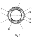
- Figures 2 and 3 show a variant of the object according to Figure 1, wherein the same parts with the same Numbers are provided and are not described again in detail.
- retaining brackets 22, 23 are inserted into the support part 10 and connected to it by spot welding, which are in contact with the support pads 20, 21 with radially inwardly directed webs 24 to 27.
- these holding brackets 22, 23 are reduced in their width perpendicular to the plane of the drawing in FIG. 3 in such a way that they do not hinder the operation of the plate spring 18 resting on the support pads 20, 21.
- the pivot point of the articulation point is as far as possible in the direction placed on the metal bellows.
Landscapes
- Engineering & Computer Science (AREA)
- General Engineering & Computer Science (AREA)
- Mechanical Engineering (AREA)
- Chemical & Material Sciences (AREA)
- Combustion & Propulsion (AREA)
- Exhaust Silencers (AREA)
- Joints Allowing Movement (AREA)
Claims (13)
- Elément de liaison articulé pour des éléments tubulaires (1, 2), notamment des éléments tubulaires de conduites d'échappement des moteurs thermiques de véhicules automobiles, constitué d'au moins un élément de conduite flexible (4), relié en étanchéité au moins indirectement aux éléments tubulaires, ainsi que d'un tube de soutien (7) disposé à l'intérieur ou à l'extérieur de l'élément de conduite et relié au moins indirectement aux éléments tubulaires, tube dont au moins une extrémité se trouve, par l'intermédiaire d'au moins une garniture de soutien (16, 17, 20, 21) présentant des propriétés d'amortissement élastique et d'un élément de soutien (10) entourant cette garniture, en liaison mutuellement porteuse, guidée en mobilité angulaire relative, avec l'élément tubulaire voisin de cette extrémité, la garniture de soutien se trouvant des deux côtés en application, en direction axiale et en direction radiale, contre le tube de soutien et/ou l'élément de soutien, caractérisé en ce que la garniture de soutien (16, 17, 20, 21) est sollicitée en pression par au moins un élément de ressort précontraint (18) agissant sur elle.
- Elément de liaison selon la revendication 1, caractérisé en ce que la garniture de soutien (16, 17, 20, 21) est sollicitée en pression dans la direction axiale et/ou dans la direction radiale de la liaison articulée.
- Elément de liaison selon la revendication 1, caractérisé en ce que l'élément de ressort (18) est disposé sur le côté de la garniture de soutien (20, 21) qui est opposé à l'élément de conduite (4) et se trouve, sur le côté opposé à la garniture de soutien, en application axiale contre le tube de soutien (7) et/ou l'élément de soutien (10).
- Elément de liaison selon la revendication 1, caractérisé en ce qu'en présence de deux garnitures de soutien (16, 17) axialement juxtaposées, l'élément de ressort (18) est placé entre ces dernières.
- Elément de liaison selon une des revendications précédentes, caractérisé en ce que l'élément de ressort est formé par au moins un disque-ressort ou rondelle-ressort (18).
- Elément de liaison selon une des revendications 1 à 4, caractérisé en ce que l'élément de ressort est formé par au moins une couronne ondulée radialement ou en direction circonférentielle.
- Elément de liaison selon une des revendications précédentes, caractérisé en ce que l'élément de ressort (18) se trouve, au moins sur le côté tourné vers la garniture de soutien (16, 17), en application contre une rondelle plate intercalée (19).
- Elément de liaison selon une des revendications 1 à 6, caractérisé en ce que la face de la garniture de soutien (20, 21) qui est tournée vers l'élément de ressort (18) est adaptée au contour voisin de l'élément de ressort ou encore correspond à ce dernier.
- Elément de liaison selon une des revendications précédentes, caractérisé en ce que chacune des extrémités du tube de soutien se trouve, par l'intermédiaire d'au moins une garniture de soutien présentant des propriétés d'amortissement élastique et d'un élément de soutien entourant cette garniture, en liaison mutuellement porteuse, guidée en mobilité angulaire relative, avec l'élément tubulaire voisin de cette extrémité.
- Elément de liaison selon une des revendications précédentes, caractérisé en ce que la garniture de soutien est formée par deux garnitures de soutien (20, 21) diamétralement opposées par rapport à l'axe d'articulation.
- Elément de liaison selon la revendication 10, caractérisé en ce que les garnitures de soutien (20, 21) sont réalisées sous la forme de segments annulaires.
- Elément de liaison selon la revendication 10 ou 11, caractérisé en ce que les garnitures de soutien (20, 21) sont supportées dans la direction circonférentielle de l'élément de liaison.
- Elément de liaison selon la revendication 12, caractérisé en ce que le support est assuré par des étriers de retenue (22, 23) fixés sur l'élément de soutien (10), qui se trouvent en application contre les garnitures de soutien (20, 21) par des branches (24 à 27) orientées radialement.
Applications Claiming Priority (2)
| Application Number | Priority Date | Filing Date | Title |
|---|---|---|---|
| DE4415991 | 1994-05-06 | ||
| DE4415991A DE4415991A1 (de) | 1994-05-06 | 1994-05-06 | Gelenkiges Verbindungselement für Rohrteile |
Publications (2)
| Publication Number | Publication Date |
|---|---|
| EP0681097A1 EP0681097A1 (fr) | 1995-11-08 |
| EP0681097B1 true EP0681097B1 (fr) | 1996-12-27 |
Family
ID=6517448
Family Applications (1)
| Application Number | Title | Priority Date | Filing Date |
|---|---|---|---|
| EP95101543A Expired - Lifetime EP0681097B1 (fr) | 1994-05-06 | 1995-02-06 | Elément de connexion flexible pour éléments tubulaires |
Country Status (2)
| Country | Link |
|---|---|
| EP (1) | EP0681097B1 (fr) |
| DE (2) | DE4415991A1 (fr) |
Families Citing this family (15)
| Publication number | Priority date | Publication date | Assignee | Title |
|---|---|---|---|---|
| DE19500264C1 (de) * | 1995-01-06 | 1996-07-11 | Iwk Regler Kompensatoren | Vorrichtung zur beweglichen Verbindung von Leitungsenden |
| US5639127A (en) * | 1995-12-08 | 1997-06-17 | Senior Engineering Investments Ag | Flexible coupler apparatus |
| US5992896A (en) * | 1995-12-08 | 1999-11-30 | Senior Engineering Investments Ag | Flexible coupler apparatus |
| EP0953124A1 (fr) * | 1997-01-17 | 1999-11-03 | Senior Engineering Investments AG | Raccord flexible |
| US6086110A (en) * | 1997-04-10 | 2000-07-11 | Senior Engineering Investments Ag | Vibration decoupling connector for exhaust systems |
| US5957504A (en) | 1997-04-10 | 1999-09-28 | Senior Engineering Investments Ag | Exhaust manifold attachment apparatus |
| US6464257B1 (en) | 1997-04-10 | 2002-10-15 | Senior Investments Ag | Vibration decoupler apparatus |
| US5984372A (en) * | 1997-04-10 | 1999-11-16 | Senior Engineering Investments Ag | Integrated flange-mesh ring assembly for decoupler apparatus |
| KR100281630B1 (ko) * | 1998-01-20 | 2001-02-15 | 김용호 | 자동차 배기관용 디커플러 |
| DE19905649A1 (de) * | 1999-02-11 | 2000-08-17 | Kloeckner Humboldt Wedag | Kompensator zum Ausgleich von Wärmedehnungen |
| US6209927B1 (en) * | 1999-09-10 | 2001-04-03 | Carrier Corporation | Isolation device and fluid connection |
| US6568715B2 (en) | 2001-05-17 | 2003-05-27 | Senior Investments Ag | Vibration decoupling exhaust connector |
| US6921112B2 (en) | 2002-11-26 | 2005-07-26 | Josif Atansoski | Exhaust vibration decoupling connector |
| WO2021021211A1 (fr) | 2019-08-01 | 2021-02-04 | Halliburton Energy Services, Inc. | Barrière de piston obturateur |
| CN115182381B (zh) * | 2022-07-25 | 2023-07-04 | 中铁二局集团建筑有限公司 | 一种地下管线安装结构 |
Family Cites Families (7)
| Publication number | Priority date | Publication date | Assignee | Title |
|---|---|---|---|---|
| DE2701022A1 (de) * | 1977-01-12 | 1978-07-13 | Volkswagenwerk Ag | Gasdichte rohrverbindung, insbesondere fuer eine abgasleitung |
| US4570440A (en) * | 1985-07-02 | 1986-02-18 | Chrysler Corporation | Articulated connector |
| EP0208128B1 (fr) * | 1985-07-12 | 1990-02-07 | Witzenmann GmbH Metallschlauch-Fabrik Pforzheim | Connexion articulée d'éléments de tube, notamment dans des conduits d'échappement de véhicules automobiles |
| DE3727915A1 (de) * | 1987-08-21 | 1989-03-02 | Opel Adam Ag | Gelenkverbindung |
| FR2645939B1 (fr) * | 1989-04-18 | 1991-06-21 | Tubest Sa | Moyens de raccordement articule pour tuyaux |
| DE4220789A1 (de) * | 1992-06-25 | 1994-01-05 | Witzenmann Metallschlauchfab | Rohrgelenk |
| DE4233644C2 (de) * | 1992-10-06 | 1994-08-18 | Burgmann Dichtungswerk Feodor | Flexible Verbindungsanordnung für zwei Rohrteile, insbesondere bei Abgasanlagen von Kraftfahrzeugen |
-
1994
- 1994-05-06 DE DE4415991A patent/DE4415991A1/de not_active Withdrawn
-
1995
- 1995-02-06 EP EP95101543A patent/EP0681097B1/fr not_active Expired - Lifetime
- 1995-02-06 DE DE59500076T patent/DE59500076D1/de not_active Expired - Lifetime
Also Published As
| Publication number | Publication date |
|---|---|
| DE59500076D1 (de) | 1997-02-06 |
| DE4415991A1 (de) | 1995-11-23 |
| EP0681097A1 (fr) | 1995-11-08 |
Similar Documents
| Publication | Publication Date | Title |
|---|---|---|
| EP0681097B1 (fr) | Elément de connexion flexible pour éléments tubulaires | |
| EP0580963B1 (fr) | Conduite articulée | |
| DE69216282T4 (de) | Flexible Kupplungseinrichtung | |
| EP0212331B1 (fr) | Raccordement de deux tuyaux d'une conduite pour milieux chauds | |
| EP0208128B1 (fr) | Connexion articulée d'éléments de tube, notamment dans des conduits d'échappement de véhicules automobiles | |
| DE3617787C2 (fr) | ||
| EP0508145B1 (fr) | Conduit d'échappement isolé par une couche d'air | |
| DE29907590U1 (de) | Abkoppelelement zur Abkopplung von Schwingungen | |
| DE2746676C2 (fr) | ||
| DE3610684A1 (de) | Gelenkige verbindung von rohrteilen, insbesondere bei abgasleitungen von kraftfahrzeugen | |
| EP1887194A1 (fr) | Dispositif de purification de gas d'échappement | |
| EP1270987A2 (fr) | Support pour un agrégat en forme de manchon | |
| DE4034055A1 (de) | Flexibles leitungselement fuer abgasleitungen von verbrennungsmotoren bei kraftfahrzeugen | |
| EP0398086B1 (fr) | Raccordement pour deux tuyaux d'un conduit pour médium chaud | |
| EP1048881B1 (fr) | Conduite de produit réfrigérant pour conditionneurs d'air | |
| EP0573764B1 (fr) | Joint articulé d'éléments de tube, notamment dans des conduits d'échappement de véhicules automobiles | |
| EP0747582A2 (fr) | Elément de découplage pour les vibrations dans les conduits | |
| EP0816738B1 (fr) | Dispositif de découplement pour vibrations dans conduits | |
| EP0295444B1 (fr) | Connexion de deux tuyaux d'une conduite pour fluides chauds | |
| EP0250901A2 (fr) | Dispositif pour désaccoupler les mouvements de torsion entre des éléments de tuyau | |
| DE19530011B4 (de) | Vorrichtung zum flexiblen, gasdichten Verbinden von Rohren | |
| EP0791731A1 (fr) | Elément de conduite flexible pour éléments tubulaires | |
| DE19642010A1 (de) | Flexible Verbindungsanordnung zum Anschluß eines Rohres einer Abgasanlage, insbesondere eines Kraftfahrzeuges, an einen Motor | |
| DE3618485A1 (de) | Gelenkverbindung zweier ein- oder mehrflutiger rohre | |
| EP0328138A2 (fr) | Arrangement de tuyau en matière métallique en particulier arrangement de tuyau ondulé ou enroule pour tuyauterie d'échappement automobiles |
Legal Events
| Date | Code | Title | Description |
|---|---|---|---|
| PUAI | Public reference made under article 153(3) epc to a published international application that has entered the european phase |
Free format text: ORIGINAL CODE: 0009012 |
|
| 17P | Request for examination filed |
Effective date: 19950206 |
|
| AK | Designated contracting states |
Kind code of ref document: A1 Designated state(s): DE FR GB |
|
| GRAG | Despatch of communication of intention to grant |
Free format text: ORIGINAL CODE: EPIDOS AGRA |
|
| 17Q | First examination report despatched |
Effective date: 19960326 |
|
| GRAH | Despatch of communication of intention to grant a patent |
Free format text: ORIGINAL CODE: EPIDOS IGRA |
|
| GRAH | Despatch of communication of intention to grant a patent |
Free format text: ORIGINAL CODE: EPIDOS IGRA |
|
| GRAA | (expected) grant |
Free format text: ORIGINAL CODE: 0009210 |
|
| AK | Designated contracting states |
Kind code of ref document: B1 Designated state(s): DE FR GB |
|
| ET | Fr: translation filed | ||
| PGFP | Annual fee paid to national office [announced via postgrant information from national office to epo] |
Ref country code: FR Payment date: 19970122 Year of fee payment: 3 |
|
| GBT | Gb: translation of ep patent filed (gb section 77(6)(a)/1977) |
Effective date: 19970102 |
|
| REF | Corresponds to: |
Ref document number: 59500076 Country of ref document: DE Date of ref document: 19970206 |
|
| PGFP | Annual fee paid to national office [announced via postgrant information from national office to epo] |
Ref country code: DE Payment date: 19970221 Year of fee payment: 3 |
|
| PLBE | No opposition filed within time limit |
Free format text: ORIGINAL CODE: 0009261 |
|
| STAA | Information on the status of an ep patent application or granted ep patent |
Free format text: STATUS: NO OPPOSITION FILED WITHIN TIME LIMIT |
|
| 26N | No opposition filed | ||
| PG25 | Lapsed in a contracting state [announced via postgrant information from national office to epo] |
Ref country code: DE Free format text: LAPSE BECAUSE OF THE APPLICANT RENOUNCES Effective date: 19980116 |
|
| PG25 | Lapsed in a contracting state [announced via postgrant information from national office to epo] |
Ref country code: FR Free format text: THE PATENT HAS BEEN ANNULLED BY A DECISION OF A NATIONAL AUTHORITY Effective date: 19980228 |
|
| REG | Reference to a national code |
Ref country code: FR Ref legal event code: ST |
|
| PG25 | Lapsed in a contracting state [announced via postgrant information from national office to epo] |
Ref country code: GB Free format text: LAPSE BECAUSE OF NON-PAYMENT OF DUE FEES Effective date: 19990206 |
|
| GBPC | Gb: european patent ceased through non-payment of renewal fee |
Effective date: 19990206 |