EP0507206B1 - Ironing machine with differential pressure control device - Google Patents
Ironing machine with differential pressure control device Download PDFInfo
- Publication number
- EP0507206B1 EP0507206B1 EP92105168A EP92105168A EP0507206B1 EP 0507206 B1 EP0507206 B1 EP 0507206B1 EP 92105168 A EP92105168 A EP 92105168A EP 92105168 A EP92105168 A EP 92105168A EP 0507206 B1 EP0507206 B1 EP 0507206B1
- Authority
- EP
- European Patent Office
- Prior art keywords
- pressure
- ironing
- board
- valves
- ironing machine
- Prior art date
- Legal status (The legal status is an assumption and is not a legal conclusion. Google has not performed a legal analysis and makes no representation as to the accuracy of the status listed.)
- Expired - Lifetime
Links
- 238000010409 ironing Methods 0.000 title claims abstract description 36
- 238000007493 shaping process Methods 0.000 claims abstract 9
- 230000001105 regulatory effect Effects 0.000 claims abstract 3
- 239000004753 textile Substances 0.000 abstract description 3
- 239000000463 material Substances 0.000 description 6
- 238000009423 ventilation Methods 0.000 description 4
- 230000006978 adaptation Effects 0.000 description 1
- 239000000654 additive Substances 0.000 description 1
- 230000000712 assembly Effects 0.000 description 1
- 238000000429 assembly Methods 0.000 description 1
- 230000000694 effects Effects 0.000 description 1
- 230000003287 optical effect Effects 0.000 description 1
- 239000000126 substance Substances 0.000 description 1
Images
Classifications
-
- D—TEXTILES; PAPER
- D06—TREATMENT OF TEXTILES OR THE LIKE; LAUNDERING; FLEXIBLE MATERIALS NOT OTHERWISE PROVIDED FOR
- D06F—LAUNDERING, DRYING, IRONING, PRESSING OR FOLDING TEXTILE ARTICLES
- D06F71/00—Apparatus for hot-pressing clothes, linen or other textile articles, i.e. wherein there is substantially no relative movement between pressing element and article while pressure is being applied to the article; Similar machines for cold-pressing clothes, linen or other textile articles
- D06F71/04—Apparatus for hot-pressing clothes, linen or other textile articles, i.e. wherein there is substantially no relative movement between pressing element and article while pressure is being applied to the article; Similar machines for cold-pressing clothes, linen or other textile articles power-actuated
- D06F71/06—Apparatus for hot-pressing clothes, linen or other textile articles, i.e. wherein there is substantially no relative movement between pressing element and article while pressure is being applied to the article; Similar machines for cold-pressing clothes, linen or other textile articles power-actuated fluid-actuated
- D06F71/062—Apparatus for hot-pressing clothes, linen or other textile articles, i.e. wherein there is substantially no relative movement between pressing element and article while pressure is being applied to the article; Similar machines for cold-pressing clothes, linen or other textile articles power-actuated fluid-actuated with an upper movable pressing member and a lower fixed pressing member
Definitions
- the invention relates to an ironing machine with a computer-assisted control device and an upper and a lower mold plate. which each have an ironing surface on their mutually facing sides and can be moved horizontally relative to one another and in which at least the upper mold plate can be moved vertically via a pressure cylinder. (see US-A-4,862,608).
- DE 39 39 024 C1 describes an ironing machine of the type mentioned which is equipped with a measuring device in order to determine the shortest distance between the upper mold plate and the goods to be ironed placed on the lower mold plate.
- the determined distance value is further processed in a computer, which determines the optimum ironing pressure and the corresponding ironing time for the items to be ironed and outputs them to a pneumatic or hydraulic control device.
- the measuring device is preferably equipped with non-contact rangefinders with optical sensors or ultrasonic sensors, and the pressure and time values can be specified on the computer in adaptation to the different types of substance.
- the invention has for its object to improve ironing machines of the type mentioned in such a way that no errors occur when setting the ironing pressure with reference to the respective ironing material, in particular due to the pressure of the weight of different upper mold plates each adapted to the ironing material.
- the solution according to the invention to the problem shown is characterized by a differential pressure control device which takes into account the weight of the respective upper mold plate, if appropriate including accessories, such as piston rod and fittings, in relation to the ironing surface when computer-controlled pressurization of the ironing goods.
- the invention prevents the weight of the upper mold plate from being transferred to the goods (textile material) in an uncontrolled manner when the upper mold plate is fed against the lower mold plate, i. H. if, with increasing pressure on the upper cylinder chamber of a pressure cylinder displacing the upper mold plate, the associated lower cylinder chamber is strongly vented.
- the weight of the upper mold plate can be, for example, 20 to 120 kg, depending on the size of the ironing surface and the desired preforming.
- the differential pressure control device for ironing machines in combination with the controlling arithmetic unit provides, in particular, in the computer to keep the pressure value required in relation to the respective piston surface of the press cylinder of the upper mold plate in balance with the weight of the respective mold plate or the pressure value to be programmed and loaded in to bring a balance in everyone Driving position of the printing cylinder is maintained in a controlled manner.
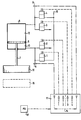
- the single figure shows a schematic representation of an ironing machine in which the differential pressure control device according to the invention is provided in connection with the upper mold plate.
- the drawing shows an upper mold plate 10 and a lower mold plate 16.
- the upper mold plate 10 is connected via one (or more) piston rod (s) 7 to the piston (s) 9 of a pressure / lifting cylinder 8 (several pressure / lifting cylinders) .
- the vertical position of the piston 9 is determined in a known manner by different pressure conditions in an upper pressure chamber 12 and a lower pressure chamber 13. These pressure conditions or pressure differences are determined and controlled by a computer 11.
- a first pressure sensor 5 is connected to the lower pressure chamber 13 and a second pressure sensor 6 is connected to the upper pressure chamber 12.
- the pressure values determined by the pressure sensors 5, 6 are sent as two input signals to the computer 11, which determines the pressure values for the upper pressure chamber 12 and the lower pressure chamber 13, taking into account the respective dead weight of the upper mold plate (including the associated piston rod 7 and piston 9) , in such a way that an optimal ironing pressure or the correct ironing time are automatically set taking into account the respective ironing material.
- the pressure chambers mentioned are each connected to a pair of a ventilation valve 1, 2 or 3, 4.
- the ventilation valves 1 and 4 are connected to a pneumatic or hydraulic pressure source 15 (not shown), while the ventilation valves 2 and 4 with a pneumatic pressure source, if necessary, via appropriate filters. Ventilate pressure reducing lines and silencers to atmospheric pressure, while in the case of a hydraulic system, ventilation valves 2 and 3 are connected to a corresponding vacuum tank.
- the valves 1 to 4 are electromagnetically actuated Valves whose control signals, as shown in dashed lines, are supplied by the computer 11.
- the counterpressure values required in relation to the piston area to compensate for the weight of the upper mold plate 10 are entered in the computer 11 via an adjusting unit 17.
- the schematically indicated pressure value P9 thus corresponds to the mold plate weight, divided by the piston area of the lower pressure chamber 13.
- the "programming pressure" in N / cm 2 (p / cm 2 ) [of the mold plate surface] is implemented on a corresponding digital display during programming.
- a very precisely controlled pressurization in the upper or lower pressure chamber of the cylinder 8 can thus be achieved via the electromagnetic valves 1 to 4. This applies to every vertical position of the piston 9, except when the piston 9 lies directly on the cylinder base.
- the invention is not limited to ironing machines in which only the upper mold plate can be moved vertically, although this embodiment will be by far the most common. It is apparent to the person skilled in the art that the invention can also be used on ironing machines in which either only the lower mold plate or in which both mold plates can be moved towards one another in the vertical direction. In the case of an ironing machine in which only the lower mold plate can be moved vertically, the considerations shown above for taking into account the weight of the respective mold plate with the opposite sign are of course to be taken into account.
Landscapes
- Engineering & Computer Science (AREA)
- Textile Engineering (AREA)
- Shaping Metal By Deep-Drawing, Or The Like (AREA)
- Irons (AREA)
Abstract
Description
Die Erfindung betrifft eine Bügelmaschine mit einer rechnergestützten Steuereinrichtung und einer oberen und einer unteren Formplatte. die an ihren einander zugekehrten Seiten jeweils eine Bügelfläche aufweisen und relativ zueinander horizontal verfahrbar sind und bei der mindestens die obere Formplatte über einen Druckzylinder vertikal verfahrbar ist. (siehe US-A-4 862 608).The invention relates to an ironing machine with a computer-assisted control device and an upper and a lower mold plate. which each have an ironing surface on their mutually facing sides and can be moved horizontally relative to one another and in which at least the upper mold plate can be moved vertically via a pressure cylinder. (see US-A-4,862,608).
In der DE-Patentschrift 39 21 024 C1 ist eine Bügelmaschine der genannten Art beschrieben, die mit einer Meßeinrichtung ausgestattet ist, um die kürzeste Entfernung zwischen der oberen Formplatte und der auf die untere Formplatte aufgelegten, zu bügelnden Ware zu ermitteln. Der ermittelte Entfernungswert wird in einem Rechner weiterverarbeitet, der daraus den für das Bügelgut optimalen Bügeldruck und die entsprechende Bügelzeit ermittelt und an eine pneumatische oder hydraulische Steuereinrichtung abgibt. wie sie beispielsweise in der DD-PS 53 040 beschrieben ist. Die Meßeinrichtung ist vorzugsweise mit berührungslos arbeitenden Entfernungsmessern mit optischen Sensoren oder Ultraschallsensoren ausgestattet, und über den Rechner lassen sich Bügeldruck- und Zeitwerte in Anpassung an die unterschiedlichen Stoffarten vorgeben.DE 39 39 024 C1 describes an ironing machine of the type mentioned which is equipped with a measuring device in order to determine the shortest distance between the upper mold plate and the goods to be ironed placed on the lower mold plate. The determined distance value is further processed in a computer, which determines the optimum ironing pressure and the corresponding ironing time for the items to be ironed and outputs them to a pneumatic or hydraulic control device. as described for example in DD-PS 53 040. The measuring device is preferably equipped with non-contact rangefinders with optical sensors or ultrasonic sensors, and the pressure and time values can be specified on the computer in adaptation to the different types of substance.
Bei der Einstellung der Vorgabewerte für die Steuereinrichtung über den Rechner arbeitet man mit Werten, die empirisch ermittelt werden. Wie sich in der Praxis gezeigt hat. wird hierbei aber entweder spezielle Fachkenntnis verlangt oder eine exakte Druckbeaufschlagung des Bügelguts ist nicht möglich, da insbesondere das Eigengewicht der oberen Formplatte samt technischen Zusätzen (Kolben, Kolbenführungsstange und dergleichen) unberücksichtigt bleiben, so daß sich das Eigengewicht der oberen Formplatte zur Druckwirkung des Preßzylinders, der die beiden Formplatten gegeneinander zustellt, summiert. Dies führt zumindest bei einigen empfindlichen Textilien zu nicht akzeptablen Bügelergebnissen.When setting the default values for the control device via the computer, one works with values that are determined empirically. As in the Practice has shown. However, if either special expertise is required or an exact pressurization of the ironing material is not possible, since in particular the dead weight of the upper mold plate including technical additives (piston, piston guide rod and the like) are not taken into account, so that the dead weight of the upper mold plate affects the pressure effect of the press cylinder, who delivers the two mold plates against each other, adds up. This leads to unacceptable ironing results, at least for some delicate textiles.
Der Erfindung liegt die Aufgabe zugrunde, Bügelmaschinen der eingangs genannten Gattung so zu verbessern, daß bei der Einstellung des Bügeldrucks mit Bezug auf das jeweilige Bügelgut keine Fehler entstehen, insbesondere aufgrund des Drucks des Eigengewichts unterschiedlicher, jeweils auf das Bügelgut angepaßter oberer Formplatten.The invention has for its object to improve ironing machines of the type mentioned in such a way that no errors occur when setting the ironing pressure with reference to the respective ironing material, in particular due to the pressure of the weight of different upper mold plates each adapted to the ironing material.
Die erfindungsgemäße Lösung des aufgezeigten Problems ist gekennzeichnet durch eine Differenzdruckregeleinrichtung, die bei der rechnergesteuerten Druckbeaufschlagung des Bügelguts das Eigengewicht der jeweiligen oberen Formplatte, gegebenenfalls samt Zubehör, wie Kolbenstange und Beschläge, in Relation zur Bügelfläche berücksichtigt.The solution according to the invention to the problem shown is characterized by a differential pressure control device which takes into account the weight of the respective upper mold plate, if appropriate including accessories, such as piston rod and fittings, in relation to the ironing surface when computer-controlled pressurization of the ironing goods.
Mit der Erfindung wird vor allem verhindert, daß das Gewicht der oberen Formplatte unkontrolliert auf die Ware (Textilmaterial) mit übertragen wird, wenn die obere Formplatte gegen die untere Formplatte zugestellt wird, d. h. wenn bei zunehmendem Druck auf die obere Zylinderkammer eines die obere Formplatte verschiebenden Druckzylinders die zugeordnete untere Zylinderkammer stark entlüftet wird.Above all, the invention prevents the weight of the upper mold plate from being transferred to the goods (textile material) in an uncontrolled manner when the upper mold plate is fed against the lower mold plate, i. H. if, with increasing pressure on the upper cylinder chamber of a pressure cylinder displacing the upper mold plate, the associated lower cylinder chamber is strongly vented.
Aufgrund der Erfindung ist es möglich, das Bügelgut mit sehr geringen Druckabstufungen zu beaufschlagen. Außerdem läßt sich mit sehr geringen, genau reproduzierbaren und vorprogrammierbaren Drücken arbeiten, beispielsweise im niedrigen Druckbereich von 9,8 · 10-2 ![]()
![]()
Die erfindungsgemäße Differenzdruckregeleinrichtung für Bügelmaschinen in Kombination mit der steuernden Recheneinheit sieht insbesondere vor, im Rechner den im Verhältnis zur jeweiligen Kolbenfläche des Preßzylinders der oberen Formplatte notwendigen Druckwert mit dem Gewicht der jeweiligen Formplatte im Gleichgewicht zu halten bzw. den zu programmierenden und zu beaufschlagenden Druckwert in ein Gleichgewicht zu bringen, das in jeder Fahrposition des Druckzylinders kontrolliert aufrechterhalten wird.The differential pressure control device according to the invention for ironing machines in combination with the controlling arithmetic unit provides, in particular, in the computer to keep the pressure value required in relation to the respective piston surface of the press cylinder of the upper mold plate in balance with the weight of the respective mold plate or the pressure value to be programmed and loaded in to bring a balance in everyone Driving position of the printing cylinder is maintained in a controlled manner.
Ein Ausführungsbeispiel der Erfindung wird nachfolgend unter Bezug auf die beigefügte Zeichnung zusammen mit weiteren vorteilhaften Einzelheiten erläutert.An embodiment of the invention is explained below with reference to the accompanying drawing together with further advantageous details.
Die einzige Figur zeigt in schematischer Darstellung eine Bügelmaschine, bei der die erfindungsgemäße Differenzdruckregeleinrichtung in Verbindung mit der oberen Formplatte vorgesehen ist.The single figure shows a schematic representation of an ironing machine in which the differential pressure control device according to the invention is provided in connection with the upper mold plate.
Alle im Zusammenhang mit der Erfindung nicht wesentlichen Teile und Baugruppen sind nicht oder nur in schematischen Umrissen dargestellt.All parts and assemblies that are not essential in connection with the invention are not shown or are only shown in schematic outlines.
Die Zeichnung zeigt eine obere Formplatte 10 und eine untere Formplatte 16. Die obere Formplatte 10 ist über eine (oder mehrere) Kolbenstange(n) 7 mit dem (den) Kolben 9 eines Druck-/Hubzylinders 8 (mehrerer Druck-/Hubzylinder) verbunden. Die Vertikalposition des Kolbens 9 ist in bekannter Weise durch unterschiedliche Druckverhältnisse in einer oberen Druckkammer 12 bzw. einer unteren Druckkammer 13 bestimmt. Diese Druckverhältnisse oder Druckunterschiede werden durch einen Rechner 11 ermittelt und gesteuert.The drawing shows an
Erfindungsgemäß ist an die untere Druckkammer 13 ein erster Drucksensor 5 und an die obere Druckkammer 12 ein zweiter Drucksensor 6 angeschlossen. Die von den Drucksensoren 5, 6 festgestellten Druckwerte gehen als zwei Eingangssignale auf den Rechner 11, welcher daraus unter Berücksichtigung des jeweiligen Eigengewichts der oberen Formplatte (einschließlich zugehöriger Kolbenstange 7 und Kolben 9) Druckwerte für die obere Druckkammer 12 bzw. die untere Druckkammer 13 ermittelt, derart, daß unter Berücksichtigung des jeweiligen Bügelguts ein optimaler Bügeldruck bzw. die richtige Bügelzeit automatisch eingestellt werden.According to the invention, a first pressure sensor 5 is connected to the lower pressure chamber 13 and a second pressure sensor 6 is connected to the
Um die errechneten Druckwerte für die obere Druckkammer 12 bzw. die untere Druckkammer 13 einzustellen, sind die genannten Druckkammern mit jeweils einem Paar eines Be- bzw. Entlüftungsventils 1, 2 bzw. 3, 4 verbunden. Die Belüftungsventile 1 bzw. 4 sind an eine pneumatische oder hydraulische Druckquelle 15 (nicht dargestellt) angeschlossen, während die Entlüftungsventile 2 bzw. 4 bei pneumatischer Druckquelle gegebenenfalls über entsprechende Filter. Druckreduzierleitungen und Schalldämpfer auf Atmosphärendruck belüften, während im Falle einer Hydraulikanlage die Belüftungsventile 2 und 3 an einen entsprechenden Unterdruckbehälter angeschlossen sind. Im dargestellten Beispiel handelt es sich bei den Ventilen 1 bis 4 um elektromagnetisch betätigbare Ventile, deren Steuersignale, wie gestrichelt dargestellt, vom Rechner 11 geliefert werden.In order to set the calculated pressure values for the
Im Rechner 11 werden außer den bereits aus der Druckschrift DE 39 21 024 C1 bekannten Werten für den bügelgutspezifischen Druck bzw. die Bügelzeit über eine Einstelleinheit 17 die im Verhältnis zur Kolbenfläche notwendigen Gegendruckwerte zum Ausgleich des Gewichts der oberen Formplatte 10 eingegeben. Der schematisch angegebene Druckwert P9 entspricht damit dem Formplattengewicht, dividiert durch die Kolbenfläche der unteren Druckkammer 13. Der zu beaufschlagende Druckwert für die obere Druckkammer 12 wird - für die gängigen Typen von oberen Formplatten 10 als Standardwert- eingegeben und durch den Rechner nach der Formel
Für den Preßdruck, der über ein digitales elektronisches Programmiersystem einzugeben ist, gilt dann entsprechend:![]()
![]()
Auf einer entsprechenden digitalen Anzeige wird bei der Programmierung der "Programmierdruck" in N/cm2 (p/cm2) [der Formplattenfläche] umgesetzt.The "programming pressure" in N / cm 2 (p / cm 2 ) [of the mold plate surface] is implemented on a corresponding digital display during programming.
Über die elektromagnetischen Ventile 1 bis 4 läßt sich damit eine sehr genau kontrollierte Druckbeaufschlagung in der oberen bzw. unteren Druckkammer des Zylinders 8 erreichen. Dies gilt für jede Vertikalposition des Kolbens 9, ausgenommen, wenn der Kolben 9 unmittelbar auf dem Zylinderboden anliegt.A very precisely controlled pressurization in the upper or lower pressure chamber of the cylinder 8 can thus be achieved via the electromagnetic valves 1 to 4. This applies to every vertical position of the
Die Erfindung ist nicht auf Bügelmaschinen beschränkt, bei denen lediglich die obere Formplatte vertikal verfahrbar ist, obwohl diese Ausführungsform bei weitem die häufigste sein wird. Für den Fachmann ist ersichtlich, daß die Erfindung auch auf Bügelmaschinen Anwendung finden kann, bei denen entweder nur die untere Formplatte oder bei welcher beide Formplatten in Vertikalrichtung aufeinander zustellbar sind. Für den Fall einer Bügelmaschine, bei der lediglich die untere Formplatte vertikal verfahrbar ist, sind selbstverständlich die oben dargestellten Überlegungen zur Berücksichtigung des Gewichts der jeweiligen Formplatte mit umgekehrten Vorzeichen zu berücksichtigen.The invention is not limited to ironing machines in which only the upper mold plate can be moved vertically, although this embodiment will be by far the most common. It is apparent to the person skilled in the art that the invention can also be used on ironing machines in which either only the lower mold plate or in which both mold plates can be moved towards one another in the vertical direction. In the case of an ironing machine in which only the lower mold plate can be moved vertically, the considerations shown above for taking into account the weight of the respective mold plate with the opposite sign are of course to be taken into account.
Claims (5)
- An ironing machine with a computer-assisted control device and an upper (10) and a lower (16) shaping board which each have an ironing surface on their mutually confronting sides, at least one of the shaping boards being vertically movable by means of a lifting/pressure cylinder (8), defined by a differential-pressure regulating device (1 to 6, 11, 17) which, during the application of pressure to the article to be ironed, takes into account by computer control the dead weight of the shaping board, if appropriate including accessories.
- The ironing machine as claimed in claim 1, wherein only the upper shaping board (10) is vertically movable.
- The ironing machine as claimed in claim 1 or 2, wherein the differential-pressure regulating device - has two pressure sensors (5, 6) which measure the pressure in the lifting/pressure cylinder (8) on the one hand above and on the other hand below a piston (9) displaceable in the cylinder,- comprises two pairs of electromagnetic aerating and deaerating valves (1, 2 and 3, 4), of which one pair of valves (1, 2) is connected jointly to the lower pressure chamber (13) and the other pair of valves (3, 4) is connected jointly to the upper pressure chamber (12), the two aerating valves (1, 4) being connected on the inlet side to a pneumatic or hydraulic high-pressure source (15) and the outlets of the deaerating valves (2, 3) being connected to a pressure sink.
- The ironing machine as claimed in one of the preceding claims, wherein the pressure values of the lower (13) and of the upper (12) pressure chamber of the cylinder (8) which are determined by the pressure sensors (5, 6) are fed into the computer (11), and in that control values for the pairs of aerating and deaerating valves (1 to 4) are so calculated in the computer, with the shaping-board weight being taken into account, that the programed effective pressure for the advancing shaping board is maintained, during the advance, at least from an advancing value corresponding to the thickness of the article to be ironed which is positioned on the other shaping board.
- The ironing machine as claimed in claim 4, wherein the values for the board weight relative to the board pressing surface which are to be taken into account in the adjustment of the ironing pressure can be preset on a setting unit (17).
Applications Claiming Priority (2)
| Application Number | Priority Date | Filing Date | Title |
|---|---|---|---|
| DE4110761 | 1991-04-03 | ||
| DE4110761A DE4110761C1 (en) | 1991-04-03 | 1991-04-03 |
Publications (2)
| Publication Number | Publication Date |
|---|---|
| EP0507206A1 EP0507206A1 (en) | 1992-10-07 |
| EP0507206B1 true EP0507206B1 (en) | 1996-07-24 |
Family
ID=6428727
Family Applications (1)
| Application Number | Title | Priority Date | Filing Date |
|---|---|---|---|
| EP92105168A Expired - Lifetime EP0507206B1 (en) | 1991-04-03 | 1992-03-25 | Ironing machine with differential pressure control device |
Country Status (5)
| Country | Link |
|---|---|
| US (1) | US5307572A (en) |
| EP (1) | EP0507206B1 (en) |
| JP (1) | JP2525991B2 (en) |
| AT (1) | ATE140736T1 (en) |
| DE (1) | DE4110761C1 (en) |
Families Citing this family (10)
| Publication number | Priority date | Publication date | Assignee | Title |
|---|---|---|---|---|
| DE59405909D1 (en) * | 1994-07-07 | 1998-06-10 | Harald Engel | Ironing machine with differential pressure control device |
| DE4428749C2 (en) * | 1994-08-13 | 1996-07-11 | Normbau Gmbh | Device and method for steaming or smoothing clothing and circuitry for use in such a device |
| IT1292062B1 (en) * | 1997-06-03 | 1999-01-25 | Rotondi Group S R L | INDUSTRIAL IRONING MACHINE EQUIPPED WITH AN IMPROVED VERTICAL MOVEMENT SYSTEM OF THE UPPER PRESS AND WITH A DEVICE |
| WO2000009793A1 (en) * | 1998-08-12 | 2000-02-24 | Warmkraft, Inc. | Centralized apparel press controller |
| DE10023164B4 (en) * | 1999-05-12 | 2006-11-30 | Hornung Gmbh Indupress & Co. Kg | ironer |
| ITMI20071571A1 (en) * | 2007-07-31 | 2009-02-01 | Maria Francesca Marchesi | MACHINERY AND COMPACTING METHOD OF RIBBONS |
| US8714081B2 (en) * | 2008-07-08 | 2014-05-06 | Sonics & Materials Inc | Press for ultrasonic welding device |
| WO2014116965A1 (en) * | 2013-01-24 | 2014-07-31 | Parker-Hannifin Corporation | Hydraulic circuit |
| CN110371746A (en) * | 2019-07-18 | 2019-10-25 | 上海航星机械(集团)有限公司 | A kind of Tensioning structure of ironing machine |
| US11234522B1 (en) | 2020-09-22 | 2022-02-01 | Joel Marvin | Support mountable seat assembly |
Family Cites Families (29)
| Publication number | Priority date | Publication date | Assignee | Title |
|---|---|---|---|---|
| DE53040C (en) * | E. H. GAZE in Walterton Road, Middlesex, England | Gas engine with gas inlets that can be triggered by the cruise control | ||
| CA472166A (en) * | 1951-03-13 | Pantex Manufacturing Corporation | Pressing machines and linkage mechanism for transmitting and transforming force for use therein | |
| US1979962A (en) * | 1929-08-14 | 1934-11-06 | Prosperity Co Inc | Garment or ironing press |
| US2080915A (en) * | 1933-08-05 | 1937-05-18 | American Laundry Mach Co | Apparatus for evacuating pressing elements |
| US2026508A (en) * | 1935-04-05 | 1935-12-31 | American Laundry Mach Co | Pressing machine control |
| US2116143A (en) * | 1935-07-12 | 1938-05-03 | American Laundry Mach Co | Press operating mechanism |
| US2332830A (en) * | 1940-09-16 | 1943-10-26 | L N Strike | Control mechanism for pressing machines |
| US2398325A (en) * | 1941-10-24 | 1946-04-09 | American Laundry Mach Co | Fabric pressing apparatus |
| US2382224A (en) * | 1943-12-06 | 1945-08-14 | A L Belle Isle | Fluid pressure control unit for laundry machines and the like |
| GB659440A (en) * | 1949-03-02 | 1951-10-24 | R G Whitaker Ltd | Improvements in garment-pressing machines |
| DE1256616B (en) * | 1962-05-15 | 1967-12-21 | Hoffman Rheem Maschinen Ges Mi | Ironing press with top plate hinged to a double-armed lever |
| US3279106A (en) * | 1964-03-20 | 1966-10-18 | Ametek Inc | Pressing machine and control |
| US3333355A (en) * | 1965-04-09 | 1967-08-01 | Ametek Inc | Combined safety and exhaust hood for pressing machine |
| US3500567A (en) * | 1969-03-26 | 1970-03-17 | Ametek Inc | Clear buck pressing machine |
| DE2049726A1 (en) * | 1970-10-09 | 1972-04-13 | Bussmann KG, 8000 München; Mannesmann Pulvermetall GmbH, 4050 Mönchengladbach | Hydraulic metal powder press |
| US3974764A (en) * | 1974-04-12 | 1976-08-17 | Horton Jr Edward L | Exhaust valve |
| US3942432A (en) * | 1974-10-15 | 1976-03-09 | Cantine Jr Thomas G | Control system for a vehicle press |
| US4030962A (en) * | 1976-02-26 | 1977-06-21 | Fitzwater Engineering Company | Heat transfer press |
| DE2808091A1 (en) * | 1978-02-24 | 1979-08-30 | Moog Gmbh | DEVICE FOR DAMPING THE CUTTING EFFECT IN HYDRAULIC PRESSES |
| US4283929A (en) * | 1979-07-16 | 1981-08-18 | Danly Machine Corporation | Coded automatic counterbalance control |
| DE2939351A1 (en) * | 1979-09-28 | 1981-04-16 | Stiebel Eltron Gmbh & Co Kg, 3450 Holzminden | Motor driven domestic ironing machine - has strain gauge strip attached to roller carrying arm to stop motor at excessive pressure |
| DE3367556D1 (en) * | 1983-01-22 | 1987-01-02 | Schuler Gmbh L | Overload protection device in presses |
| US4524582A (en) * | 1983-03-31 | 1985-06-25 | Cincinnati Incorporated | Control system for hydraulic presses |
| JPS6130599A (en) * | 1984-07-23 | 1986-02-12 | Osaka Chem Lab | Adrenocortial hormone product |
| AU607756B2 (en) * | 1987-04-24 | 1991-03-14 | American Laundry Machinery, Inc. | Garment press |
| JPH062200B2 (en) * | 1987-07-29 | 1994-01-12 | 幸男 宮田 | Iron finishing device |
| DE8710876U1 (en) * | 1987-08-08 | 1987-09-24 | Kasper, Karl-Heinz, 2805 Stuhr | Control device for an ironing device |
| DE3921024C1 (en) * | 1989-06-27 | 1991-01-10 | Harald Perchtoldsdorf At Engel | Ironing machine with computer based control device - has measuring device with transmitter and receiver spatially separated and connected to computer |
| JPH0790400B2 (en) * | 1989-10-18 | 1995-10-04 | アイダエンジニアリング株式会社 | Press die cushion equipment |
-
1991
- 1991-04-03 DE DE4110761A patent/DE4110761C1/de not_active Expired - Lifetime
-
1992
- 1992-03-25 EP EP92105168A patent/EP0507206B1/en not_active Expired - Lifetime
- 1992-03-25 AT AT92105168T patent/ATE140736T1/en not_active IP Right Cessation
- 1992-04-02 US US07/862,484 patent/US5307572A/en not_active Expired - Fee Related
- 1992-04-03 JP JP4082341A patent/JP2525991B2/en not_active Expired - Lifetime
Also Published As
| Publication number | Publication date |
|---|---|
| ATE140736T1 (en) | 1996-08-15 |
| JPH07163799A (en) | 1995-06-27 |
| JP2525991B2 (en) | 1996-08-21 |
| DE4110761C1 (en) | 1992-04-02 |
| EP0507206A1 (en) | 1992-10-07 |
| US5307572A (en) | 1994-05-03 |
Similar Documents
| Publication | Publication Date | Title |
|---|---|---|
| DE69313585T2 (en) | Die cushion and method for optimizing its cylinder pin pressure | |
| EP0507206B1 (en) | Ironing machine with differential pressure control device | |
| DE3843593C2 (en) | ||
| DE69833396T2 (en) | Hydraulic press for the production of metal plates | |
| DE69203679T2 (en) | Hydraulic cushion arrangement for a press with adjustable hydraulic energy supply for setting the initial pressure of the cylinders of the pressure bolts. | |
| EP0173755B1 (en) | Drawing device in a press | |
| DE10043557B4 (en) | Slide inclination correcting device in a pressing machine | |
| DE69105804T2 (en) | Procedure for controlling the parallel guidance of two press beams. | |
| EP0275875A2 (en) | Adjustment device for universal roll stand | |
| DE3111925A1 (en) | Process and device for saving compressed air, in particular in thermoforming machines | |
| DE69011077T2 (en) | RULE ARRANGEMENT FOR PRESS BRAKE. | |
| EP0308762A1 (en) | Position control device for a hydraulic advance drive, in particular a hydraulic press or stamping machine | |
| DE4031645A1 (en) | Hydroelastic deep-drawing die-cushion control for press - provides unequal distances for accelerations of workpiece holder and die attaining identical speeds at synchronism point | |
| DE102017114596A1 (en) | Method and device for regulating the deep-drawing process during the press stroke | |
| EP0673695A1 (en) | Method and control arrangement for interrupting and continuing of the drawing process in double acting presses, in particular hydraulic presses | |
| DE19718841A1 (en) | Material flow control for bending sheet metal workpiece | |
| DE3842030C2 (en) | ||
| DE69405426T2 (en) | Process and hydraulic press for pressing sheet metal | |
| EP0691431B1 (en) | Ironing machine with differential pressure control device | |
| DE4337825A1 (en) | Process for simulating the load-dependent ram tilting of mechanical presses on a hydraulic incorporation press | |
| DE10249809B4 (en) | Press | |
| DE3835010C2 (en) | ||
| DE1164965B (en) | Hydraulic sheet metal drawing press | |
| DE19641160B4 (en) | Loading system for the top rollers of the pull-off and pull-off roller pairs on combing machines | |
| EP0639435B1 (en) | Press for moulding under pressure ceramic articles |
Legal Events
| Date | Code | Title | Description |
|---|---|---|---|
| PUAI | Public reference made under article 153(3) epc to a published international application that has entered the european phase |
Free format text: ORIGINAL CODE: 0009012 |
|
| AK | Designated contracting states |
Kind code of ref document: A1 Designated state(s): AT FR GB IT NL |
|
| 17P | Request for examination filed |
Effective date: 19930402 |
|
| 17Q | First examination report despatched |
Effective date: 19940712 |
|
| GRAH | Despatch of communication of intention to grant a patent |
Free format text: ORIGINAL CODE: EPIDOS IGRA |
|
| GRAH | Despatch of communication of intention to grant a patent |
Free format text: ORIGINAL CODE: EPIDOS IGRA |
|
| GRAA | (expected) grant |
Free format text: ORIGINAL CODE: 0009210 |
|
| AK | Designated contracting states |
Kind code of ref document: B1 Designated state(s): AT FR GB IT NL |
|
| REF | Corresponds to: |
Ref document number: 140736 Country of ref document: AT Date of ref document: 19960815 Kind code of ref document: T |
|
| ITF | It: translation for a ep patent filed | ||
| ET | Fr: translation filed | ||
| GBT | Gb: translation of ep patent filed (gb section 77(6)(a)/1977) |
Effective date: 19960927 |
|
| ET | Fr: translation filed | ||
| PLBE | No opposition filed within time limit |
Free format text: ORIGINAL CODE: 0009261 |
|
| STAA | Information on the status of an ep patent application or granted ep patent |
Free format text: STATUS: NO OPPOSITION FILED WITHIN TIME LIMIT |
|
| 26N | No opposition filed | ||
| REG | Reference to a national code |
Ref country code: GB Ref legal event code: IF02 |
|
| PGFP | Annual fee paid to national office [announced via postgrant information from national office to epo] |
Ref country code: AT Payment date: 20020322 Year of fee payment: 11 |
|
| PGFP | Annual fee paid to national office [announced via postgrant information from national office to epo] |
Ref country code: GB Payment date: 20020701 Year of fee payment: 11 |
|
| PGFP | Annual fee paid to national office [announced via postgrant information from national office to epo] |
Ref country code: NL Payment date: 20020717 Year of fee payment: 11 Ref country code: FR Payment date: 20020717 Year of fee payment: 11 |
|
| PG25 | Lapsed in a contracting state [announced via postgrant information from national office to epo] |
Ref country code: GB Free format text: LAPSE BECAUSE OF NON-PAYMENT OF DUE FEES Effective date: 20030325 Ref country code: AT Free format text: LAPSE BECAUSE OF NON-PAYMENT OF DUE FEES Effective date: 20030325 |
|
| PG25 | Lapsed in a contracting state [announced via postgrant information from national office to epo] |
Ref country code: NL Free format text: LAPSE BECAUSE OF NON-PAYMENT OF DUE FEES Effective date: 20031001 |
|
| GBPC | Gb: european patent ceased through non-payment of renewal fee |
Effective date: 20030325 |
|
| PG25 | Lapsed in a contracting state [announced via postgrant information from national office to epo] |
Ref country code: FR Free format text: LAPSE BECAUSE OF NON-PAYMENT OF DUE FEES Effective date: 20031127 |
|
| NLV4 | Nl: lapsed or anulled due to non-payment of the annual fee |
Effective date: 20031001 |
|
| REG | Reference to a national code |
Ref country code: FR Ref legal event code: ST |
|
| PG25 | Lapsed in a contracting state [announced via postgrant information from national office to epo] |
Ref country code: IT Free format text: LAPSE BECAUSE OF NON-PAYMENT OF DUE FEES;WARNING: LAPSES OF ITALIAN PATENTS WITH EFFECTIVE DATE BEFORE 2007 MAY HAVE OCCURRED AT ANY TIME BEFORE 2007. THE CORRECT EFFECTIVE DATE MAY BE DIFFERENT FROM THE ONE RECORDED. Effective date: 20050325 |