EP0507131B1 - Tropfenschlagerosionsgeschützte Turbinenschaufel und Verfahren zu ihrer Herstellung - Google Patents
Tropfenschlagerosionsgeschützte Turbinenschaufel und Verfahren zu ihrer Herstellung Download PDFInfo
- Publication number
- EP0507131B1 EP0507131B1 EP92104368A EP92104368A EP0507131B1 EP 0507131 B1 EP0507131 B1 EP 0507131B1 EP 92104368 A EP92104368 A EP 92104368A EP 92104368 A EP92104368 A EP 92104368A EP 0507131 B1 EP0507131 B1 EP 0507131B1
- Authority
- EP
- European Patent Office
- Prior art keywords
- blade
- hardening
- hardness
- leading edge
- erosion
- Prior art date
- Legal status (The legal status is an assumption and is not a legal conclusion. Google has not performed a legal analysis and makes no representation as to the accuracy of the status listed.)
- Expired - Lifetime
Links
Images
Classifications
-
- F—MECHANICAL ENGINEERING; LIGHTING; HEATING; WEAPONS; BLASTING
- F01—MACHINES OR ENGINES IN GENERAL; ENGINE PLANTS IN GENERAL; STEAM ENGINES
- F01D—NON-POSITIVE DISPLACEMENT MACHINES OR ENGINES, e.g. STEAM TURBINES
- F01D5/00—Blades; Blade-carrying members; Heating, heat-insulating, cooling or antivibration means on the blades or the members
- F01D5/12—Blades
- F01D5/28—Selecting particular materials; Particular measures relating thereto; Measures against erosion or corrosion
- F01D5/286—Particular treatment of blades, e.g. to increase durability or resistance against corrosion or erosion
-
- C—CHEMISTRY; METALLURGY
- C21—METALLURGY OF IRON
- C21D—MODIFYING THE PHYSICAL STRUCTURE OF FERROUS METALS; GENERAL DEVICES FOR HEAT TREATMENT OF FERROUS OR NON-FERROUS METALS OR ALLOYS; MAKING METAL MALLEABLE, e.g. BY DECARBURISATION OR TEMPERING
- C21D1/00—General methods or devices for heat treatment, e.g. annealing, hardening, quenching or tempering
- C21D1/06—Surface hardening
- C21D1/09—Surface hardening by direct application of electrical or wave energy; by particle radiation
-
- C—CHEMISTRY; METALLURGY
- C21—METALLURGY OF IRON
- C21D—MODIFYING THE PHYSICAL STRUCTURE OF FERROUS METALS; GENERAL DEVICES FOR HEAT TREATMENT OF FERROUS OR NON-FERROUS METALS OR ALLOYS; MAKING METAL MALLEABLE, e.g. BY DECARBURISATION OR TEMPERING
- C21D9/00—Heat treatment, e.g. annealing, hardening, quenching or tempering, adapted for particular articles; Furnaces therefor
- C21D9/0068—Heat treatment, e.g. annealing, hardening, quenching or tempering, adapted for particular articles; Furnaces therefor for particular articles not mentioned below
Definitions
- the invention relates to the surface hardening of machine components.
- Objects for which their application is possible and expedient are all machine components made of martensitic chrome steels which are subject to dripping or cavitation and which are used at operating temperatures below 250 ° C.
- the invention can be used particularly advantageously to protect end-stage rotor blades of steam turbines which are heavily erosively loaded by tropical impact.
- the blades of steam turbines are subject to a constant impact of water droplets during their operation, which leads to premature wear and thus destruction of the blades by drop impact erosion.
- the flame hardening process is usually carried out at austenitizing temperatures of approx. 1000 to 1100 ° C. These austenitization temperatures only lead to a relatively low release of carbon from the (Fe, Cr) mixed carbides during the austenitization times that can be achieved in terms of process engineering. The lack of the method is consequently insufficient hardening on the surface.
- the inductor can only be designed optimally for one contour of the zones near the leading edge, but the contour changes greatly over the length of the airfoil.
- the hardness has already dropped to 500-530 HV0.1 or 480-560 HV1 at a depth of, for example, 0.2 mm.
- the disadvantageous effect of the hardness drop results from the fact that on the one hand Drop impact load with the drop sizes and drop impact velocities occurring in the low-pressure part of steam turbines, the maximum of the reference stress lies at a fairly large depth of 0.05 mm to 0.2 mm and, on the other hand, the wear with intensive drop impact load only after the formation of a typical surface roughness with roughness depths of a few 10 ⁇ m to a few 100 ⁇ m reaches a steady state.
- a realistically large hardness gradient that is too steep and also begins on the surface therefore prevents a steady state of wear even with sufficient surface hardness.
- the cause of the drop in hardness is that too little carbon is released from the (Fe, Cr) mixed carbides in the depths in question.
- the deficiency of the process is therefore that sufficient carbon is only released from the (Fe, Cr) mixed carbides in the immediate vicinity of the surface, which is necessary to achieve high hardnesses.
- the reason for this results from the fact that the temperature gradient of the indicated short-term curing is so steep that the peak temperature of the local temperature-time cycle is already too low at the depths in question.
- the aim of the invention is to provide a turbine blade which is better protected against drop impact erosion and to propose a method for its production.
- the invention has for its object to provide a hardening zone formation for the leading edges of turbine blades, in which there is a sufficiently high surface hardness for the typical conditions of the drop impact load in final stages of steam turbines and in which, even after the surface roughening typical of the load has been formed, the maximum of the reference stress is still in one sufficiently hard area.
- this object is achieved with a turbine blade made of martensitic chromium steel which is protected against drip erosion and has a short-term hardened leading edge whose erosion-protected zone has a constant surface hardness over the entire area of the blade back side which is at risk of erosion, as shown in claims 1 to 4.
- the advantageous embodiment of the invention described in claim 2 makes advantageous use of the fact that usually the strength and area of the drop impact load increases sharply towards the tip of the blade, while the cyclical load decreases, so that the wear resistance is sufficient due to the decrease
- the hardening zone width improves the residual stress state at the leading edge and the toughness reserves of the blade can be increased.
- the task is solved by a short-term hardening process for martensitic chromium-alloyed turbine blade steels, in which a peak temperature of the local temperature-time cycle is reached even at the required depth of 0.1 mm to approximately 0.9 mm, with which a complete temperature is achieved Carbide dissolution takes place without a property-deteriorating austenite grain coarsening already taking place on the surface.
- the fact is advantageously taken into account that if the airfoil thickness falls below about 3 mm, the cooling rate already decreases in the temperature range in which austenite grain coarsening can take place due to poorer heat dissipation options.
- the final stage blade of a 100 MW turbine which is subject to dripping impact, is to be provided with a wear-resistant leading edge.
- the expected erosion zone width is 18 mm at the tip of the blade and decreases too little towards the blade root.
- the hardening system used consists of a CO2 cross-current laser with a nominal power of 5 kW, a motion machine that serves to realize the relative movement between the laser beam and the leading edge and whose control allows simultaneous movement in at least 4 coordinates.
- the area to be hardened is covered with an approximately 80 ⁇ m thick layer of black board paint or similar. provided that serves as an absorbent for the laser radiation.
- a suitable set of irradiation parameters (laser power, beam defocusing, oscillation amplitude, feed rate) is determined based on nomograms, which leads to the formation of the hardening zone according to the invention at every point of the leading edge.
- the contour control program is then created by scanning the blade leading edge.
- the inclination of the area to be hardened relative to the laser beam is chosen so that, in cooperation with the set power density distribution of the laser beam transversely to the feed direction, a constant temperature is established in the most wear-stressed zone (the later very hard layer 2).
- the power density distribution in the laser beam can be varied to a sufficient degree by the choice of the ratio of the oscillation amplitude of the beam A to the radius of the steel r.
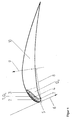
- the turbine blade hardened with these parameters has a hardening zone at the leading edge 5 of the following geometrical dimensions, hardness and hardness distribution: Width of the entire hardening zone 1 on the blade back (for the position of the hardening zones see FIG. 1) at the blade tip: 20.2 mm; Width of hardening zone 1 at a distance of 150 mm from the tip of the blade: 18.7 mm; Total hardening depth 4: 1.17 mm to 2.9 mm depending on the distance to the leading edge, width of the entire hardening zone 1 on the blade belly side 7: 2.8 mm near the blade tip; Surface hardness in the very hard layer 2: 700 HV0.05 ⁇ 35 HV0.05; Depth of the very hard layer 2: 0.1 mm to 0.45 mm, decreasing with increasing distance from the leading edge, tapering at the leading edge approximately at the location of the greatest curvature of the airfoil profile.
- the hardness gradient in the very hard layer 2 is ⁇ 30 HV / mm.
- the width of the very hard layer 2 near the blade tip is about 19 mm.
- the length of the entire hardening zone 1 is 185 mm. It leaves the blade at an exit angle of 45 °.
- the reproducibility of the desired hardness-depth curve according to the invention is very good.
- both the depth of the very hard layer 2 and the total hardening depth 4 increase with increasing distance Leading edge from.
- the position of the reference stress maximum is less than a third of the depth of the very hard layer 2. A property-worsening coarsening of the austenite grain size does not occur.
Landscapes
- Chemical & Material Sciences (AREA)
- Engineering & Computer Science (AREA)
- Mechanical Engineering (AREA)
- Materials Engineering (AREA)
- Physics & Mathematics (AREA)
- Thermal Sciences (AREA)
- Crystallography & Structural Chemistry (AREA)
- Metallurgy (AREA)
- Organic Chemistry (AREA)
- General Engineering & Computer Science (AREA)
- Heat Treatment Of Articles (AREA)
- Turbine Rotor Nozzle Sealing (AREA)
Applications Claiming Priority (2)
| Application Number | Priority Date | Filing Date | Title |
|---|---|---|---|
| DE4110941 | 1991-03-30 | ||
| DE4110941A DE4110941A1 (de) | 1991-03-30 | 1991-03-30 | Tropfenschlagerosionsgeschuetzte turbinenschaufel und verfahren zu ihrer herstellung |
Publications (2)
| Publication Number | Publication Date |
|---|---|
| EP0507131A1 EP0507131A1 (de) | 1992-10-07 |
| EP0507131B1 true EP0507131B1 (de) | 1995-10-11 |
Family
ID=6428829
Family Applications (1)
| Application Number | Title | Priority Date | Filing Date |
|---|---|---|---|
| EP92104368A Expired - Lifetime EP0507131B1 (de) | 1991-03-30 | 1992-03-13 | Tropfenschlagerosionsgeschützte Turbinenschaufel und Verfahren zu ihrer Herstellung |
Country Status (2)
| Country | Link |
|---|---|
| EP (1) | EP0507131B1 (enExample) |
| DE (2) | DE4110941A1 (enExample) |
Families Citing this family (10)
| Publication number | Priority date | Publication date | Assignee | Title |
|---|---|---|---|---|
| JPH11182204A (ja) * | 1997-12-15 | 1999-07-06 | Toshiba Corp | タービン動翼 |
| DE10056241B4 (de) * | 2000-11-14 | 2010-12-09 | Alstom Technology Ltd. | Niederdruckdampfturbine |
| EP2096263A1 (de) * | 2008-02-29 | 2009-09-02 | Siemens Aktiengesellschaft | Tropfenschlagschutzschicht für eine Schaufel |
| JP2011007093A (ja) * | 2009-06-25 | 2011-01-13 | Hitachi Ltd | タービン動翼 |
| WO2011057661A1 (de) * | 2009-11-11 | 2011-05-19 | Siemens Aktiengesellschaft | Bauteil mit bereichen unterschiedlicher duktilität und verfahren zur herstellung eines bauteils |
| DE102010036042B3 (de) * | 2010-08-31 | 2012-02-16 | Lufthansa Technik Ag | Verfahren zum Rekonturieren einer Kompressor- oder Turbinenschaufel für eine Gasturbine |
| US9291062B2 (en) | 2012-09-07 | 2016-03-22 | General Electric Company | Methods of forming blades and method for rendering a blade resistant to erosion |
| US20170240985A1 (en) * | 2016-02-24 | 2017-08-24 | General Electric Company | Method of treatment, turbine component, and turbine system |
| CN108930664A (zh) * | 2017-05-24 | 2018-12-04 | 中国航发商用航空发动机有限责任公司 | 混合结构航空发动机风扇叶片 |
| CN109083798B (zh) * | 2017-06-13 | 2024-02-06 | 国网江苏省电力公司常州供电公司 | 流体发电装置 |
Family Cites Families (2)
| Publication number | Priority date | Publication date | Assignee | Title |
|---|---|---|---|---|
| CH483558A (de) * | 1968-11-08 | 1969-12-31 | Deutsche Edelstahlwerke Ag | Laufschaufel für Kondensationsturbinen |
| CH564089A5 (enExample) * | 1972-03-13 | 1975-07-15 | Bbc Brown Boveri & Cie |
-
1991
- 1991-03-30 DE DE4110941A patent/DE4110941A1/de active Granted
-
1992
- 1992-03-13 DE DE59203939T patent/DE59203939D1/de not_active Expired - Lifetime
- 1992-03-13 EP EP92104368A patent/EP0507131B1/de not_active Expired - Lifetime
Also Published As
| Publication number | Publication date |
|---|---|
| DE4110941C2 (enExample) | 1993-07-08 |
| DE59203939D1 (de) | 1995-11-16 |
| DE4110941A1 (de) | 1992-10-01 |
| EP0507131A1 (de) | 1992-10-07 |
Similar Documents
| Publication | Publication Date | Title |
|---|---|---|
| EP0507131B1 (de) | Tropfenschlagerosionsgeschützte Turbinenschaufel und Verfahren zu ihrer Herstellung | |
| EP1066913B9 (de) | Verfahren zur Herstellung einer Klinge eines Schneidwerkzeuges und damit hergestelltes Erzeugnis | |
| EP0697503B1 (de) | Verfahren zur Herstellung einer Turbinenschaufel aus einer (alpha-Beta)-Titan-Basislegierung | |
| DE69805946T2 (de) | Metallisches Bauteil und ein Verfahren zum Laserschockbestrahlen eines metallischen Bauteils | |
| DE102004033342A1 (de) | Verfahren zur Herstellung von verschleißbeständigen und ermüdungsresistenten Randschichten in Titan-Legierungen und damit hergestellte Bauteile | |
| EP1213363B1 (de) | Verfahren zur Erzeugung verschleissbeständiger Randschichten an Bauteilen aus ausscheidungshärtbaren metallischem Werkstoff | |
| DE69218767T2 (de) | Messerklingen | |
| Riabkina-Fishman et al. | Laser alloying and cladding for improving surface properties | |
| WO2011036045A1 (de) | Laufschaufel zur verwendung in zweiphasenströmungen sowie verfahren zum herstellen einer solchen laufschaufel | |
| EP0751234B1 (de) | Stammblatt einer Säge, wie einer Kreis- oder Gattersäge, einer Trennscheibe, einer Schneide- oder einer Schabvorrichtung | |
| EP1008659A1 (de) | Verfahren zur Herstellung eines Bleches aus martensitaushärtendem Stahl | |
| EP0640693A1 (de) | Papiermesser und Verfahren zu dessen Herstellung | |
| DE3142270C2 (de) | Verfahren zum Verbessern der Festigkeit von Werkstückoberflächen | |
| WO1991001386A1 (de) | Verfahren zum härten der schneidkanten von sägen, messern und stanzwerkzeugen | |
| DE10059802B4 (de) | Verfahren zur Oberflächenvergütung | |
| EP3962691B1 (de) | Anordnung zur modifizierung von oberflächen metallischer bauteile | |
| DE2232932A1 (de) | Verschleiss- und warmfestes werkstueck aus stahl mit gehaerteter oberflaeche zur verwendung als maschinenteil | |
| DE102014222526A1 (de) | Verfahren und Vorrichtung zum generativen Herstellen zumindest eines Bauteilbereichs eines Bauteils | |
| DE19902818C2 (de) | Metallmesser mit speziell angepaßter Materialhärtenverteilung für Zerkleinerungs- und Schneidmaschinen | |
| EP3635150B1 (de) | Verfahren zum behandeln der oberflaechen von aus einem stahlwerkstoff bestehenden formteilen für giessformen | |
| DE4233516A1 (de) | Verfahren zur erzeugung einer verschleissfesten schicht | |
| EP2226151B1 (de) | Fertigungsverfahren für einen Turbinenläufer | |
| JPH06173604A (ja) | 水滴衝撃侵蝕防止タービンブレード及びその製造方法 | |
| EP2161095A1 (de) | Verfahren zur Oberflächenbehandlung eines Turbinenteils | |
| DD270090A1 (de) | Verfahren zur oberflaechenschmelzveredelung mit elektronenstrahlen |
Legal Events
| Date | Code | Title | Description |
|---|---|---|---|
| PUAI | Public reference made under article 153(3) epc to a published international application that has entered the european phase |
Free format text: ORIGINAL CODE: 0009012 |
|
| AK | Designated contracting states |
Kind code of ref document: A1 Designated state(s): CH DE FR GB IT LI |
|
| 17P | Request for examination filed |
Effective date: 19920910 |
|
| 17Q | First examination report despatched |
Effective date: 19940127 |
|
| GRAA | (expected) grant |
Free format text: ORIGINAL CODE: 0009210 |
|
| AK | Designated contracting states |
Kind code of ref document: B1 Designated state(s): CH DE FR GB IT LI |
|
| GBT | Gb: translation of ep patent filed (gb section 77(6)(a)/1977) |
Effective date: 19951010 |
|
| REF | Corresponds to: |
Ref document number: 59203939 Country of ref document: DE Date of ref document: 19951116 |
|
| ET | Fr: translation filed | ||
| ITF | It: translation for a ep patent filed | ||
| PLBE | No opposition filed within time limit |
Free format text: ORIGINAL CODE: 0009261 |
|
| STAA | Information on the status of an ep patent application or granted ep patent |
Free format text: STATUS: NO OPPOSITION FILED WITHIN TIME LIMIT |
|
| 26N | No opposition filed | ||
| REG | Reference to a national code |
Ref country code: GB Ref legal event code: IF02 |
|
| REG | Reference to a national code |
Ref country code: CH Ref legal event code: PFA Owner name: FRAUNHOFER-GESELLSCHAFT ZUR FOERDERUNG DER ANGEWA Free format text: FRAUNHOFER-GESELLSCHAFT ZUR FOERDERUNG DER ANGEWANDTEN FORSCHUNG E.V.#LEONRODSTRASSE 54#D-80636 MUENCHEN 19 (DE) -TRANSFER TO- FRAUNHOFER-GESELLSCHAFT ZUR FOERDERUNG DER ANGEWANDTEN FORSCHUNG E.V.#HANSASTRASSE 27 C#80686 MUENCHEN (DE) |
|
| REG | Reference to a national code |
Ref country code: CH Ref legal event code: PCAR Free format text: ALDO ROEMPLER PATENTANWALT;BRENDENWEG 11 POSTFACH 154;9424 RHEINECK (CH) |
|
| PGFP | Annual fee paid to national office [announced via postgrant information from national office to epo] |
Ref country code: CH Payment date: 20110328 Year of fee payment: 20 Ref country code: FR Payment date: 20110401 Year of fee payment: 20 |
|
| PGFP | Annual fee paid to national office [announced via postgrant information from national office to epo] |
Ref country code: GB Payment date: 20110324 Year of fee payment: 20 |
|
| PGFP | Annual fee paid to national office [announced via postgrant information from national office to epo] |
Ref country code: IT Payment date: 20110330 Year of fee payment: 20 Ref country code: DE Payment date: 20110526 Year of fee payment: 20 |
|
| REG | Reference to a national code |
Ref country code: DE Ref legal event code: R071 Ref document number: 59203939 Country of ref document: DE |
|
| REG | Reference to a national code |
Ref country code: DE Ref legal event code: R071 Ref document number: 59203939 Country of ref document: DE |
|
| REG | Reference to a national code |
Ref country code: CH Ref legal event code: PL |
|
| REG | Reference to a national code |
Ref country code: GB Ref legal event code: PE20 Expiry date: 20120312 |
|
| PG25 | Lapsed in a contracting state [announced via postgrant information from national office to epo] |
Ref country code: DE Free format text: LAPSE BECAUSE OF EXPIRATION OF PROTECTION Effective date: 20120314 |
|
| PG25 | Lapsed in a contracting state [announced via postgrant information from national office to epo] |
Ref country code: GB Free format text: LAPSE BECAUSE OF EXPIRATION OF PROTECTION Effective date: 20120312 |