EP0506520B1 - Gerät zur Ermittlung der Blutströmung - Google Patents
Gerät zur Ermittlung der Blutströmung Download PDFInfo
- Publication number
- EP0506520B1 EP0506520B1 EP92400726A EP92400726A EP0506520B1 EP 0506520 B1 EP0506520 B1 EP 0506520B1 EP 92400726 A EP92400726 A EP 92400726A EP 92400726 A EP92400726 A EP 92400726A EP 0506520 B1 EP0506520 B1 EP 0506520B1
- Authority
- EP
- European Patent Office
- Prior art keywords
- artery
- output signal
- pressure sensor
- blood
- detection
- Prior art date
- Legal status (The legal status is an assumption and is not a legal conclusion. Google has not performed a legal analysis and makes no representation as to the accuracy of the status listed.)
- Expired - Lifetime
Links
Images





Classifications
-
- A—HUMAN NECESSITIES
- A61—MEDICAL OR VETERINARY SCIENCE; HYGIENE
- A61B—DIAGNOSIS; SURGERY; IDENTIFICATION
- A61B5/00—Measuring for diagnostic purposes; Identification of persons
- A61B5/48—Other medical applications
- A61B5/4854—Diagnosis based on concepts of alternative medicine, e.g. homeopathy or non-orthodox
-
- A—HUMAN NECESSITIES
- A61—MEDICAL OR VETERINARY SCIENCE; HYGIENE
- A61B—DIAGNOSIS; SURGERY; IDENTIFICATION
- A61B5/00—Measuring for diagnostic purposes; Identification of persons
- A61B5/02—Detecting, measuring or recording for evaluating the cardiovascular system, e.g. pulse, heart rate, blood pressure or blood flow
- A61B5/021—Measuring pressure in heart or blood vessels
- A61B5/022—Measuring pressure in heart or blood vessels by applying pressure to close blood vessels, e.g. against the skin; Ophthalmodynamometers
- A61B5/02233—Occluders specially adapted therefor
- A61B5/02241—Occluders specially adapted therefor of small dimensions, e.g. adapted to fingers
-
- A—HUMAN NECESSITIES
- A61—MEDICAL OR VETERINARY SCIENCE; HYGIENE
- A61B—DIAGNOSIS; SURGERY; IDENTIFICATION
- A61B5/00—Measuring for diagnostic purposes; Identification of persons
- A61B5/02—Detecting, measuring or recording for evaluating the cardiovascular system, e.g. pulse, heart rate, blood pressure or blood flow
- A61B5/024—Measuring pulse rate or heart rate
- A61B5/02416—Measuring pulse rate or heart rate using photoplethysmograph signals, e.g. generated by infrared radiation
- A61B5/02422—Measuring pulse rate or heart rate using photoplethysmograph signals, e.g. generated by infrared radiation within occluders
Definitions
- the present invention relates to a blood flow detection apparatus, and in particular to an apparatus for detecting the blood circulation function of a patient without contacting the blood, by observing the wave form of the arterial pulses.
- Cardiographic or ultrasonic tomographic diagnosis apparatus has heretofore been used for examination of heart disease.
- the arterial pulses related with the motion of the heart contain important information representative of the condition of the blood circulating function, they are widely used for determining whether or not the blood circulating function is good. Observation of the volumetric pulses representative of the content of blood in the capillary vessels has generally been conducted.
- a method of converting changes in pressure due to the heart beat into electrical signals by using a piezo-electric element or capacitor microphone or a method for optically detecting changes in the amount of blood flow by using optical modulating action of hemoglobin in blood has been adopted for detecting the arterial pulses.
- the conditions of a patient are determined by sphygmic diagnosis solely relying on the sense of touch of the arterial pulses on the "sunko", that is, the difficulties styloideus radii on the inner side of the wrist.
- the pulses on the "sunko” are classified into those on three spots, such as upper, middle and lower spots which are referred to as “shun” "khan” and “shaku”, respectively and two kinds of pulsation condition "myakki” on the pulse route "keimyaku” appearing on respective spots are sensed.
- the term “shun” means the distal end side of the artery of the wrist.
- the pulses on the “shun” represent the health conditions of the patient from the head to the chest.
- the term “khan” means the middle artery of the wrist between the distal end and the heart.
- the pulses on the “khan” represents the health conditions between the chest and the navel.
- the term “shaku” means the heart side of the artery in the wrist and the pulses on the "shaku” represents the health conditions between the navel and the toe.
- a sphygmic diagnosis apparatus in which arterial pulses are detected from the artery of a human being by means of sensors such as infra-red ray sensor or pressure sensor for performing the diagnosis by observation of the sphygmogram has heretofore been known as is disclosed in the specification of the Japanese Examined Patent Publication No. 57-52054.
- the disclosed diagnosis apparatus comprises three pressure sensors 51, 52 and 53 for converting the arterial pulses on the three spots such as “shun”, “khan” and “shaku” of the "sunko” into electrical signal waves and a cuff band 55 which is mounted on the wrist 54 of a patient for biasing the pressure sensors 51, 52 and 53 upon the artery of the wrist as shown in Fig. 1.
- the pressure sensors 51, 52 and 53 are disposed on the wrist 54, that is, on and along the artery in the "sunko" and the cuff 55 is wrapped around the wrist. Compressed air is pumped into an air bag (not shown) provided on the cuff 55 from a pneumatic pump via a conduit 56. The arterial pulses can be measured by adjusting the amount of the pumped air to change the pressure applied upon the artery.
- the pressure sensors 51, 52 and 53 comprise, for example, so-called electrostatic microphones or piezoelectric microphones. Specifically, in the case of the electrostatic microphone, a high d.c. voltage is applied across an electrode of a vibrating plate and a fixed electrode of the vibrating plate is brought into direct contact with a spot on which a pressure is detected, for example the alter of the "sunko". The spacing between the electrode of the vibrating plate and the fixed electrode is changed due to pressure to change the electrostatic capacity therebetween. The voltage generated at this time is detected.
- the pressure sensors 51, 52 and 53 are connected with an electromagnetic oscillograph and the like through connection wires 51a, 52a and 53a respectively so that the measured arterial pulses are recorded on a recording paper and the like for observing the sphygmogram.
- cardiography or ultrasonic tomography has been used for examination of heart disease as mentioned above, it is very hard to quantitatively diagnose the condition of the heart disease by observing the condition of the blood circulating function in no contact with blood. Confirmation of abnormality has been visually carried out by well experienced medical doctors.
- a method of estimating the hardness of the artery by pressing a sensor for investigating the relation between stress and strain upon the radial artery has been known as a method of measuring the hardness of the artery without contact with blood.
- this method is strongly influenced by the tissue between the artery and the upper skin. Accordingly, this method is inaccurate so that the hardness of the artery cannot be quantified.
- EP-A-0 487 726 (applicable as prior art in relation to the present application under Article 54(3) EPC) describes blood flow velocity measuring apparatus comprising a cuff with front and rear detecting bags. Sensors in these detecting bags detect arterial pulses as the pressure biasing the cuff against the artery is decreased. Blood velocity is determined from the relative timing of pulse detection at the detecting bags.
- the present invention was made to overcome the above drawbacks.
- the present invention provides a blood circulating function detection apparatus, comprising: first, second and third pressure sensors for detecting arterial pulses on the heart, intermediate and peripheral sides, respectively, which are spaced from each other by a predetermined distance and which are for positioning at detection positions along an artery and which are for biasing against the artery by biasing means; and biasing pressure controlling means for controlling the biasing force exerted by the biasing means to obtain a restricted condition of blood flow; characterized in that the apparatus further comprises: a first level detecting means for detecting that a detection output having a level not lower than a predetermined level is obtained by said first pressure sensor; a second level detecting means for detecting that a detection output having a level not lower than a predetermined level is obtained by said second pressure sensor; timing means for measuring a first period of time between an output signal from the first level detecting means and an output from said second level detecting means; and outputting means which, based on the output signal from said timing means, outputs blood viscosity measurement data.
- the blood circulating function observing apparatus of the present invention is formed as shown in Fig.2 .
- the blood circulating function observing apparatus of the present invention is applied to a sphygmic diagnosis apparatus which determines the disease of a patient by detecting the arterial pulses at spots such as "shun", “khan”, “shaku” of "sunko” in the oriental medicine.
- the observing apparatus comprises first to third pressure sensors 1, 2 and 3 which detect the arterial pulses of "shun, "khan”, “shaku” of the sunko and convert them into electrical signals.
- Output signals S 1 , S 2 and S 3 from the pressure sensors 1, 2 and 3 are supplied to an output unit 4 for observing the wave forms of the detection output signals S 1 , S 2 and S 3 .
- the output unit 4 may be a display for displaying the wave forms of the signals S 1 , S 2 and S 3 on a screen or a printer for printing the wave forms of the detected output signals S 1 , S 2 and S 3 on a recording paper.
- the first to third pressure sensors 1, 2 and 3 comprise pressure-electric converting elements such as piezoelectric microphones for detecting the arterial pulses of the shun, khan and shaku of the sunko as changes in pressure.
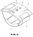
- the first to third pressure sensors 1, 2 and 3 are disposed on the inner wall of a fixing plate 6 having opposite ends which are connected to each other via a cuff band 5 which will be worn around the wrist of a patient as shown in Fig. 3.
- the first to third pressure sensors 1, 2 and 3 are pressed upon the positions of detection corresponding to the shun, khan and shaku of the sunko in the oriental medicine by the admission of air into an air bag 7 provided on the cuff band 5 for pressing a skin tissue S of the wrist of the patient to block an artery A.
- Air is charged into or from the air bag 7 provided in the cuff band 5 from an air pump (not shown) which is controlled by a biasing control unit 8 and the air is discharged via an exhaust valve (not shown) which is controlled by the biasing control unit 8.
- the biasing pressure supplied by the first to third pressure sensors 1, 2 and 3 of the air bag 7 are detected by a fourth pressure sensor 9.
- the first pressure sensor 1 which detects the shun of the sunko, i.e. the artery pulse on the side of the heart supplies the detection output signal S 1 to the output unit 4 and to a first level detecting circuit 10 and a notch detecting circuit 11.
- the first level detecting circuit 10 detects when the detection output signal S 1 from the first pressure sensor 1 assumes a predetermined output level. A detection output signal from the first level detecting circuit 10 is supplied to first and third timer circuits 12 and 15 as a timer start signal.
- the first notch detecting circuit 11 detects a notch (omitted portion of the wave form) contained in the arterial pulses on the side of the heart, i.e in the detection output signal S 1 from the first pressure sensor 1.
- the first notch detecting circuit 11 comprises a low pass filter 11A for extracting a fundamental wave component of the detection output signal S 1 from the first pressure sensor 1 and a subtracter 11B for subtracting the fundamental wave component extracted by the low pass filter 11A from the detection output signals of the first pressure sensor 1.
- a first notch signal which is obtained as the subtraction output signal from the subtracter 11B is supplied to the first timer circuit 12 as a timer stop signal and to an integrating circuit 14 and to a second timer circuit 13 as a timer start signal.
- the first timer circuit 12 measures a period of time since the first level detecting circuit 10 detects that the detection output signal S 1 having a level higher than a predetermined level is obtained until the first notch detecting circuit 11 detects the notch contained in the detection output signal S 1 from the first pressure sensor 1.
- a measurement output signal from the first timer circuit 12 is supplied to the output unit 4.
- the integrating circuit 14 integrates the first notch detection signal from the first notch detecting circuit 11.
- the integration output signal from the integrating circuit 14 is supplied to the output unit 4.
- the second pressure sensor 2 which detects the khan of the sunko, i.e. the artery pulse between the heart and peripheral side supplies the detection output signal S 2 to the output unit 4 and to a second level detecting circuit 16 and a notch detecting circuit 17.
- the second level detecting circuit 16 detects when the detection output signal S 2 from the second pressure sensor 2 reaches a predetermined output level. An output signal from the second level detecting circuit 16 is supplied to the output unit 4 and the biasing control unit 8 and to a third timer circuit 15 as a timer stop signal and to a first latch circuit 18 as a first latch signal.
- the third timer circuit 15 measures a period of time since the first level detecting circuit 10 detects that the detection output signal S 1 having a level higher than a predetermined level is obtained until the second level detecting circuit 16 detects that the detection output signal S 2 higher than a predetermined level is obtained from the second pressure sensor 2.
- a measurement output signal from the third timer circuit 15 is supplied to the output unit 4.
- the second notch detecting circuit 17 detects a notch (omitted portion of the wave form) contained in the detection output signal S 2 from the second pressure sensor 2, i.e. in the arterial pulses between the heart and the peripheral sides.
- the second notch detecting circuit 17 comprises a low pass filter 17A for extracting a fundamental wave component of the detection output signal S 2 from the second pressure sensor 2 and a subtracter 17B for subtracting the fundamental wave component extracted by the low pass filter 17A from the detection output signal S 2 of the second pressure sensor 2.
- a second notch signal which is obtained as the subtraction output signal from the subtracter 17B is supplied to a second timer circuit 13 as a timer stop signal.
- the second timer circuit 13 measures the period of time since the first notch detecting circuit 11 detects a notch contained in the detection output signal S 1 from the first pressure sensor 1 until the second notch detecting circuit 17 detects a notch contained in the detection output signal S 2 from the second pressure sensor 2. A measurement output signal from the second timer circuit 13 is supplied to output unit 4.
- the third pressure sensor 3 which detects the shun of sunko, i.e. the arterial pulse on the peripheral side supplies the detection output signal S 3 to the output unit 4 and to a third level detecting circuit 19.
- the third level detecting circuit 19 detects when the detection output signal S 3 from the third pressure sensor 3 reaches a predetermined output level.
- the detection output signal from the third level detecting circuit 19 is supplied to a second latch circuit 20 as a second latch signal.
- the fourth pressure sensor 9 while detects the biasing forces of the first to third pressure sensors 1, 2 and 3 exerted by the air bag 7 supplies the detection output signal S 4 to the first and second latch circuits 18 and 20.
- the first latch circuit 18 latches the detection output signal S 4 from the fourth pressure sensor 9 in response to the first latch signal, i.e the detection output signal from the second level detecting circuit 16 and supplies the latch output signal to a subtracter 21 and a divider 22.
- the latch output signal from the first latch circuit 18 represents the blood flow full passage pressure P 1 at which the detection output signal S 2 not less than a predetermined level is obtained from the second pressure sensor 2.
- the second latch circuit 20 latches the detection output signal S 4 from the fourth pressure sensor 9 in response to the second latch signal, i.e. the detection output signal from the third level detecting circuit 19 and supplies the latch output signal to a subtracter 21.
- the latch output signal from the second latch circuit 20 represents the blood flow full passage pressure P 2 at which the detection output signal S 3 not less than a predetermined level is obtained from the third pressure sensor 3.
- the subtracter 21 subtracts the latch output signal from the second latch circuit 20 from the latch output signal from the first latch circuit 18 and supplies the subtraction output signal to the divider 22.
- the subtraction output signal from the subtracter 21 represent a pressure difference P 1 - P 2 which is a difference between the blood flow full passage pressure P 1 at which the blood fully passes through the first pressure sensor 1 represented by the latch output signal from the first latch circuit 18 and the blood flow full passage pressure P 2 at which the blood fully passes through the second pressure sensor 2 which is represented by the latch output signal from the second latch circuit 20.
- the divider 22 normalizes the pressure difference P 1 - P 2 which is represented by the subtraction output signal by dividing the subtraction output signal of the subtracter 21 by the latch output signal from the first latch circuit 18.
- the detection output signal from the division output signal from the divider 22, i.e. the normalized pressure difference (P 1 - P 2 )/P 1 from the divider 22 is supplied to the output unit 4.
- the sphygmic diagnosis apparatus which is formed in such a manner is used in a selected one of first to third operative modes.
- the biasing force of the first to third pressure sensors 1, 2 and 3 by the air bag 7 is gradually released to change from the blood flow blocked condition to the full passage condition by controlling a pneumatic pump and an exhaust valve (not shown) by the biasing pressure control unit 8.
- the wave shape of each of the detection output signals S 1 , S 2 and S 3 of the first to third pressure sensors 1, 2 and 3 is observed. Accordingly, the disease of the patient can be diagnosed by observing the arterial pulses of the shun, khan and shaku of the sunko in oriental medicine.
- the level of the detection output signal S 1 of the first pressure 1 which is located on the side of the heart is firstly elevated and then the level of the detection output signal S 2 of the second pressure sensor 2 which is located in the intermediate position is elevated and finally the level of the detection output signal S 3 of the third pressure sensor 3 which is located in the terminal position is elevated as shown in Fig.5. If the biasing force is lowered, the levels of the detection output signals S 1 , S 2 and S 3 of the first to third pressure sensors 1, 2 and 3 are simultaneously lowered.
- the biasing force of the first to third pressure sensors 1, 2 and 3 exerted by the air bag 7 is gradually lowered from the blood flow blocked condition and the pneumatic pump and the exhaust valve (not shown) are controlled by the biasing force control unit 8 in response to the detection output signal from the second level detecting circuit 16 so that the biasing pressure P 1 is maintained constant on a blood flow passage restricted condition on which the detection output signal can be obtained from the second level detecting circuit 16.
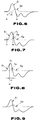
- each of the detection output signals S 1 and S 2 obtained by the first and second pressure sensors 1 and 2 have a smooth continuous sinusoidal wave form from the time t 1 when the ventricle of the heart begins to contract to the time t 2 when the aorta valve closes as shown in Fig. 6 in which the wave forms of the detection output signals S 1 and S 2 of the first and second pressure sensors 1 are depicted by the solid dotted lines, respectively if the blood circulating function of the patient is normal.
- a notch occurs during an interval from the time t 1 when the ventricle of the heart begins to contract to the time t 2 when the aorta valve closes. If there is an abnormality of the fast pressure propagation due to valve abnormality, notches n 1 and n 2 appear at the substantially same time t n as shown in Fig. 7 in which the wave forms of the detection output signals S 1 and S 2 are depicted by the solid and dotted lines, respectively. If there is an abnormality of the slow propagation flow due to abnormality in the heart muscle, notches n 1 and n 2 appear at times having a time difference ⁇ t therebetween as shown in Fig. 8 in which the wave forms of the detection output signals S 1 and S 2 of the first and second pressure sensors 1 and 2 are depicted by solid and dotted lines, respectively
- first timer circuit 12 measures the period of time t n from the time t 1 when the ventricle of the heart begins to contract until the notch n 1 appears in the detection output signal S 1 of the first pressure sensor 1 and the second timer circuit 13 measures the period of time since the notch n appears in the detection output signal of the first pressure sensor 1 until the notch n 2 appears in the detection output signal S 2 of the second pressure sensor 2, i.e. the time difference ⁇ t of the notches n 1 and n 2 and the output unit 4 outputs the time information t n and ⁇ t of the notches n 1 and n 2 .
- the measurement data t n , ⁇ t of the first and second timer circuits 12 and 13 are outputted from the output unit 4 as blood flow circulating function observing data in such a manner. Therefore, the blood circulating function condition of the patient can be properly diagnosed in non-contact with blood without any experience.
- the disease condition can be quantified by determining the size (area) of the notch n by integrating in the integrating circuit 14 the first notch detection signal from the first notch detecting circuit 11 which detects the notch n 1 appearing in the detection output signal S 1 of the first pressure sensor 1. Diagnosis of the disease can be more properly performed by displaying or printing the integration output signal from the integrating circuit 14 as blood circulating function observing data.
- the third timer circuit 15 measures the period of time ⁇ since the first level detector 10 detects that the detection output signal S 1 not less than a predetermined level is obtained by the first pressure sensor 1 until the second level detecting circuit 16 detects that the detection output signal S 2 not less than a predetermined level is obtained from the second pressure sensor 2, i.e. the time which is taken for the blood to move by a distance L between the first and second pressure sensors 1 and 2.
- the velocity v at which the blood moves through the first pressure sensor 1 on the blood flow passage restricted condition is represented by equation 1.
- v ⁇ 1 ⁇ wherein ⁇ represents the viscosity of blood.
- the viscosity can be estimated by measuring the time ⁇ which is taken for the blood to move by a distance L between the first and second pressure sensors 1 and 2.
- the output unit 4 to which the detection output signal is supplied from the third timer circuit 15 outputs the measurement ⁇ of the time which is taken for the blood to move by a distance L between the first and second pressure sensors 1 and 2 as a measurement data of the blood viscosity ⁇ . Accordingly, information on the blood viscosity which is obtained by normalizing the arterial blood viscosity ⁇ can be obtained in a manner that does not require contact,
- the wave forms of a comparison output signal between a reference wave form signal based upon the detection output signal S 1 from the first pressure sensor 1 and the detection output signal S 2 from the second pressure sensor 2 is displayed or printed out by the output unit 4 as observation information on the condition of the inner wall of the blood vessel.
- the blood which moves through the first pressure sensor 1 on the blood flow passage restricted condition as a thin film flow exhibits a wave surface (representing the elevation and lowering of pressure ) depending upon the roughness of the inner wall of the artery.
- the detection output signal S 2 from the second pressure sensor 2 has a wave form depending upon the roughness of the inner wall of the artery as shown in Fig. 9. Accordingly, information on the roughness of the inner wall of the artery can be obtained in no contact manner with the blood.
- the wave form of each of the detection output signals S 1 and S 2 from the first pressure sensor 1 on the heart side and the intermediate second pressure sensor 2 is observed. Since there is provided the third pressure sensor 3 on the peripheral side, accurate wave form observation can be made by removing the influences of the blood on the peripheral side.
- the pneumatic pump and exhaust valve (not shown) are controlled by the biasing control unit 8 so that the biasing force of the first to third pressure sensors 1, 2 and 3 exerted by the air bag 7 is gradually lowered from the blood flow blocked condition.
- Information on the normalized pressure difference (P 1 - P 2 )/P 1 represented by the division output signal from the divider 22 is outputted from the output unit as obtained information on the hardness of the artery.
- the pressure difference P 1 - P 2 between the blood flow full passage pressure P 1 at which the blood fully passes through the first pressure sensor 1 on the heart side and the blood full passage pressure P 2 at which the blood fully passes through the intermediate second pressure sensor 2 can be used as information representative of the hardness of the artery of the wrist of the patient. Since the blood flow full passage pressure point is a point where the load is balanced with the maximum blood pressure via the skin tissue, the pressure difference P 1 - P 2 is hardly influenced by the differences of blood pressure or skin tissues among persons.
- the pressure difference P 1 - P 2 is displayed or printed out by the output unit 4 as observation information on the hardness of the artery having differences among persons due to blood pressure, etc. by normalizing the pressure difference by the divider 22. Accordingly, observation information on the hardness of the artery can be obtained in no contact manner with blood.
- observation of the blood circulating function, the viscosity of the blood, and the hardness of the artery of a patient can be performed in the output unit by observing the wave form of the arterial pulses.
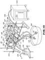
- a simulated blood circulating apparatus comprises a simulated blood circulating passage 101 in which the blood circulating system of a human body is simulated, an atrium portion reservoir 102 for reserving the simulated blood which flows through the simulated blood circulating passage 101, an artificial heart unit 103 for supplying the simulated blood reserved in the atrium portion reservoir 102 to the simulated blood circulating passage 101 and an artificial heart driving unit 104 for driving the artificial heart unit 103 as shown in Fig. 10.
- the simulated blood circulating passage 101 is formed of tubing having circular section of a rubber resin (silicon and natural rubbers) in which the wall thickness of the tube, Young Modulus, tensile strength, dimension and compliance are preset to adapt to simulation of a human body and comprises the arch of the aorta portion 111, the brachiocephalic artery portion 112, the right common carotid artery portion 113, the right subclavian artery portion 114, the left common carotid artery portion 115, the left subclavian artery portion 116, the right ulnar artery portion 117, the right radial artery portion 118, the left ulnar artery portion 119, the left radial artery portion 120, the right hand artery portion 121, and left hand artery portion 122, corresponding to the arch of the aorta, the left brachiocephalic, artery, the right common carotid artery, the right subclavian artery, the left common caroti
- the arch of the aorta portion 111 which is connected with the artificial heart unit 103 comprises a connection portion 111A having an inner diameter D 1 of 27.5 mm, a curved portion 111B extending from the connection portion 111A having a curvature radius R 1 and a downward depending portion 111C extending from the curved portion 111B and at a curvature radius R 2 and having an inner diameter D 2 of 17.5 mm.
- the arch of the aorta 111 are 1.5 mm, 2.0 mm, and 2.5 mm in wall thickness.
- the length L 1 between the top of the curved portion 111B and the lower end of the downward depending portion 111C is 200 mm.
- the arch of the aorta portion 111 is branched at the curved portion 111B into the brachiocephalic portion 112, the left common carotid artery portion 115 and the left subclavian artery portion 116 and the brachiocephalic portion 112 is branched at the top thereof into the right common carotid artery portion 113 and the right subclavian artery portion 114.
- the inner diameters D 3 and D 4 of the right and left common carotid artery portions 113 and 114 are 11 mm.
- the inner diameter D 5 and D 6 of the right and left subclavian artery portions 114 and 116 are 8 mm.
- the right subclavian portion 114 is formed so that it has a length L 2 of 550 mm and is branched at the tip end thereof into the right ulnar artery portion 117 and right radial artery portion 118 which have lengths L 3 and L 4 of 350 mm, respectively and is connected at the tip ends thereof with the right hand artery portion 121.
- the length L 5 of the right hand artery 121 is 700 mm.
- the left subclavian portion 116 is formed so that it has a length L 6 of 420 mm and is branched at the tip end thereof into the left ulnar artery portion 119 and left radial artery portion 120 which have lengths L 7 and L 8 of 350 mm, respectively and is connected at the tip ends thereof with the left hand artery portion 122.
- the length L 9 of left hand artery 121 is 700 mm.
- the right subclavian artery portion 114 simulates the right subclavian artery and the axillary artery and the brachial artery similarly the left subclavian artery portion 116 simulates the left subclavian artery, the axillary artery and the brachial artery.
- the right ulnar artery portion 117 and right radial artery portion 118 simulate, at the connection portion with the right hand artery portion 121, the superficial palmer venous arch and the deep palmer arch.
- the left ulnar artery portion 119 and left radial artery portion 120 simulate, at the connection portion with the left hand artery portion 122, the superficial palmer venous arch and the deep palmer arch.
- the simulated blood circulating passage 101 having such a structure is supported on a stand 105 in a substantially horizontal manner as shown in Fig. 10.
- the downward depending portion 111C of the arch of the aorta 111, the right common carotid artery portion 113 and the left common carotid artery portion 115 have respective outlet portions at the tip ends thereof which are introduced into the vein reservoir 106.
- the right and left hand artery portions 121 and 122 have respective outlet portions at the tip ends thereof, which are introduced into the vein portion reservoir 107.
- Clips 131, 132, 133, 134 and 135, the gripping forces of which are adjustable by screwing are mounted on the downward depending portion 111C of the arch of the aorta portion 111, the right and left common carotid artery portions 113 and 115, the right and left hand artery portions 121 and 122 in the vicinity of the respective outlets at the tip ends thereof so that the resistances of the respective passages can be variably preset by the clips 131, 132, 133, 134 and 135, respectively.
- Clips 141, 142 and 143, 144, the gripping forces preset by spring members are mounted on the right and left subclavian artery portions 114 and 116 so that the resistances of the respective passages are preset by the clips 141, 142 and 143, 144, respectively.
- the pipe 123 of the simulated blood circulating passage 101 is connected with the artificial heart unit 103 to form a passage for supplying simulated blood reserved in the atrium reservoir 102 to the artificial heart unit 103.
- the atrium reservoir 102 is replenished with simulated blood via a replenishing pipe 108.
- the artificial heart unit 103 is driven by supplying driving compressed air from the artificial heart driving unit 104, the artificial heart unit 103 pumps out simulated blood which is supplied from the atrium reservoir 102 through the pipe 123 into the arch of the aorta portion 111 of the simulated blood circulating passage 101.
- the simulated blood is supplied to the simulated blood circulating passage 101 from the artificial heart unit 103 by driving the artificial heart unit 103.
- the simulated blood which is supplied to the simulated blood circulating passage 101 is discharged to the vein reservoir 106 from respective outlets at the tip end of the downward depending portion 111C of the arch of the aorta portion 111, the right and left common carotid artery portions 113 and 115 and from the right and left hand artery portions 121 and 122.
- the passages of the arch of the aorta portion 111, the right brachiocephalic portion 112, the right subclavian artery portion 114 and the right ulnar artery portion 117, the right radial artery portion 118 and the right hand artery portion 121 of the simulated blood circulating passage 101 simulate the artery portion in the right hand of the blood circulating system of the human body.
- Sphygmic diagnosis simulation can be performed by measuring the arterial pulses in three points a, b and c of the right radial artery portion 118 corresponding to three positions of the shun, khan and shaku of the sunko in the oriental medicine.
- the passages of the arch of the aorta portion 111, the left subclavian artery portion 116 and the left ulnar artery portion 119, the left radial artery portion 120 and the left hand artery portion 122 of the simulated blood circulating passage 101 simulated the artery portion in the left hand of the blood circulating system of the human body.
- Sphygmic diagnosis simulation can be performed by measuring the arterial pulses in three points a, b and c of the left radial artery portion 119 corresponding to three positions of the shun, khan and shaku of the sunko in the oriental medicine.
- a notch contained in the detection output signal from the first pressure sensor which detects the arterial pulses on the heart side is detected by the first notch detecting circuit and a notch contained in the detection output signal from the second pressure sensor which detects the arterial pulses on the peripheral side on the blood flow passage limit condition in which a detection output signal having a predetermined level can be obtained by the second pressure sensor which detects the arterial pulses on the peripheral side.
- the blood circulating function observation data are obtained as notch occurrence time information and are outputted from the output means. Accordingly, the condition of the blood circulating function of the patient can be properly diagnosed in a noncontact manner with blood without any calling on any particular experience.
- the blood viscosity observing data which are quantified as the time difference between the time when the detection output signal is obtained by the first pressure sensor which detects the arterial pulses on the heart side and the time detection output signal is obtained by the second pressure sensor which detects the arterial pulses on the peripheral side are obtained and outputted from the output means on the blood flow passing limit condition in which the detection output signal having a predetermined level is obtained by the second pressure sensor which detects the arterial pulses on the peripheral side.
- the blood flow passage limitation is conducted at the same pressure in three positions which are closely positioned along the artery in the artery hardness observing apparatus of the present invention.
- the arterial pulses in the intermediate and peripheral positions of the three biasing positions which are closely disposed along the artery are detected by the first and second pressure sensors, respectively.
- the biasing force exerted by biasing means to restrict the blood flow is detected by the third pressure sensor.
- the detection signal representative of the difference in level between the detection output signals which are obtained by the third pressure sensor on the blood flow passage restricted conditions in which the first and second pressure sensors obtain detection output signals having predetermined levels can be obtained as observation information on the quantified hardness of the artery.
- the hardness of artery of the patient can be properly diagnosed in a non-contact manner with blood without any experience. Accordingly, the information on the hardness of the artery can be used for the diagnosis of the heart disease.
Landscapes
- Health & Medical Sciences (AREA)
- Life Sciences & Earth Sciences (AREA)
- Medical Informatics (AREA)
- Cardiology (AREA)
- Engineering & Computer Science (AREA)
- Biomedical Technology (AREA)
- Surgery (AREA)
- Biophysics (AREA)
- Pathology (AREA)
- Veterinary Medicine (AREA)
- Vascular Medicine (AREA)
- Heart & Thoracic Surgery (AREA)
- Public Health (AREA)
- Molecular Biology (AREA)
- Physics & Mathematics (AREA)
- Animal Behavior & Ethology (AREA)
- General Health & Medical Sciences (AREA)
- Dentistry (AREA)
- Physiology (AREA)
- Alternative & Traditional Medicine (AREA)
- Ophthalmology & Optometry (AREA)
- Measuring Pulse, Heart Rate, Blood Pressure Or Blood Flow (AREA)
Claims (10)
- Blutzirkulationsfunktions-Erfassungsvorrichtung, aufweisendeinen ersten, einen zweiten und einen dritten Drucksensor (1, 2, 3) zur Erfassung von arteriellen Pulsen auf der Herzseite, mittleren Seite, bzw. äußeren Seite, die voneinander einen festgelegten Abstand (L) aufweisen und die zur Positionierung an Erfassungspositionen entlang einer Arterie und zum Andrücken gegen die Arterie mittels einer Andrückvorrichtung (7) ausgebildet sind; undeine Andrück-Drucksteuereinrichtung (8) zur Steuerung der durch die Andrückvorrichtung (7) ausgeübten Andrückkraft, um einen Zustand beschränkten Blutflusses zu erhalten;
dadurch gekennzeichnet, daß die Vorrichtung ferner aufweist:eine erste Pegelerfassungseinrichtung (10, 11) zur Erfassung, daß ein Erfassungs-Ausgangssignal mit einem Pegel, der nicht kleiner als ein festgelegter Pegel ist, durch den ersten Drucksensor (1) erhalten wird;eine zweite Pegelerfassungseinrichtung (16, 17) zur Erfassung, daß ein Erfassungs-Ausgangssignal mit einem Pegel, der nicht kleiner als ein festgelegter Pegel ist, durch den zweiten Drucksensor (2) erhalten wird;eine Zeiterfassungseinrichtung (12, 13, 15) zur Messung einer ersten Zeitperiode zwischen einem Ausgangssignal von der ersten Pegelerfassungseinrichtung (10, 11) und einem Ausgangssignal von der zweiten Pegelerfassungseinrichtung (16, 17); undeine Ausgabeeinrichtung (4), die basierend auf dem Ausgabesignal von der Zeiterfassungseinrichtung die Blutviskositätsmeßdaten ausgibt. - Blutzirkulationsfunktions-Erfassungsvorrichtung gemäß Anspruch 1,
bei der die Zeiterfassungseinrichtung (12, 13, 15) ein erstes Zeiterfassungselement (15) aufweist, das die Zeitperiode (τ) mißt zwischen:a) der Erfassung durch die erste Pegelerfassungseinrichtung (10), daß das Ausgangssignal vom ersten Drucksensor (1) nicht geringer als der entsprechende festgelegte Pegel ist, undb) der Erfassung durch die zweite Pegelerfassungseinrichtung (16), daß das Ausgangssignal des zweiten Drucksensors (2) nicht geringer als der entsprechende festgelegte Wert ist; undwobei die Ausgabeeinrichtung (4) die Blutviskositätmeßdaten, die aus der gemessenen Zeitperiode und aus dem Abstand zwischen erstem und zweitem Sensor (1, 2) erhalten werden, ausgibt. - Blutzirkulationsfunktions-Erfassungsvorrichtung gemäß Anspruch 1 oder 2, wobei;die erste Pegelerfassungseinrichtung ferner eine erste Signallücken-Erfassungseinrichtung (11) zur Erfassung einer Signallücke in dem Erfassungs-Ausgabesignal von dem ersten Drucksensor (1) aufweist;die zweite Pegelerfassungseinrichtung ferner eine zweite Signallücken-Erfassungseinrichtung (17) zur Erfassung einer Signallücke in dem Erfassungs-Ausgangssignal von dem zweiten Drucksensor (2) aufweist;die Zeiterfassungseinrichtung aufweist;(i) ein zweites Zeiterfassungselement (13), das die Zeit zwischen einer in dem Ausgangssignal von dem ersten Drucksensor (1) auftretenden Signallücke und einer in dem Ausgangssignal von dem zweiten Drucksensor (2) auftretenden Signallücke mißt, und(ii) ein drittes Zeiterfassungselement (12), das die Zeit zwischen der Erfassung durch die erste Pegelerfassungseinrichtung (10), daß das Ausgangssignal vom ersten Drucksensor (1) nicht geringer ist als der entsprechende festgelegte Pegel und dem Auftreten einer Signallücke in dem Erfassungs-Ausgabesignal vom ersten Drucksensor (1) mißt; undeine Ausgabeeinrichtung (4) Klappen- oder Muskelabnormalitätsdaten ausgibt, die aus den gemessenen Zeitperioden erhalten werden.
- Blutzirkulationsfunktions-Erfassungsvorrichtung gemäß einem der Ansprüche 1 bis 3,
wobei erster bis dritter Drucksensor (1-3) an Erfassungspunkten entlang der Arterie nahe beieinander angeordnet sind; wobei ferner ein Andrück-Drucksensor (9) zur Erfassung der durch die Andrückeinrichtung (7) ausgeübten Andruckkraft und eine Berechnungseinrichtung (21) zur Berechnung der Differenz (B) zwischen einem durch den Andrück-Drucksensor (9) gemessenen Ausgabesignal (A), das infolge eines Signals von der zweiten Pegelerfassungseinrichtung (16) des zweiten Drucksensors (2) festgehalten ist und einen Zustand beschränkten Blutflusses angibt und einem weiteren durch den Andrück-Drucksensor (9) gemessenen Ausgabesignal, das infolge eines Signals von einer dritten Pegelerfassungseinrichtung (19) des dritten Drucksensors festgehalten ist und einen Zustand beschränkten Blutflusses angibt; und wobei die Ausgabeeinrichtung (4) Arterienhärtedaten ausgibt, die aus der Differenz (B) der festgehaltenen Drucksignale vom Andrück-Drucksensor (9) erhalten werden. - Blutzirkulationsfunktions-Erfassungsvorrichtung gemäß Anspruch 4,
bei der die Berechnungseinrichtung aufweist:eine erste Halteeinrichtung (18) zum Festhalten des Erfassungs-Ausgangssignals (A) von dem Andrück-Drucksensor (9) infolge des Erfassungs-Ausgangssignals von der zweiten Pegelerfassungseinrichtung (16);eine zweite Halteeinrichtung (20) zum Festhalten des Erfassungs-Ausgangssignals von dem Andrück-Drucksensor (9) infolge der Erfassung eines Ausgangssignals von der dritten Pegelerfassungseinrichtung (19); undeine Differenzerfassungseinrichtung (21) zur Erfassung einer Differenz (B) zwischen den Halteausgabesignalen von erster und zweiter Halteeinrichtung (18, 20). - Blutzirkulationsfunktions-Erfassungsvorrichtung gemäß Anspruch 4,
bei der die Berechnungseinrichtung eine Differenz (B) zwischen einem ersten Halteausgabesignal, das erhalten wird durch Festhalten des Erfassungs-Ausgabesignals von dem Andrück-Drucksensor (9) infolge des Erfassungs-Ausgabesignals von der zweiten Pegelerfassungseinrichtung (16) und einem zweiten Halteausgabesignal, das erhalten wird durch Festhalten des Erfassungs-Ausgabesignals von dem Andrück-Drucksensor (9) infolge des Erfassungs-Ausgabesignals von der dritten Pegelerfassungseinrichtung (19) durch ein erstes Halteausgabesignal (A) dividiert. - Blutzirkulationsfunktions-Erfassungsvorrichtung gemäß einem der Ansprüche 1 bis 6, wobei die Ausgabeeinrichtung (4) ferner eine Referenzwellenform basierend auf dem Erfassungs-Ausgabesignal von dem ersten Drucksensor (1) und eine Wellenform basierend auf dem Erfassungs-Ausgabesignal von dem zweiten Drucksensor (2) ausgibt und dabei Information betreffend den Zustand der Innenwand des Blutgefäßes liefert.
- Vorrichtung zur Simulation einer Blutzirkulationsdiagnose für einen Patienten mit einem künstlichen Herzen, aufweisend:eine Zirkulationsvorrichtung für eine Blut repräsentierende Flüssigkeit, aufweisend ein Reservoir (102) zur Aufbewahrung der Flüssigkeit, eine künstliche Herzeinheit (103), der die Flüssigkeit von dem Reservoir (102) zugeführt wird, eine Ansteuereinheit (104) des künstlichen Herzens zur Ansteuerung der künstlichen Herzeinheit und eine Zirkülationspassage (101), der die Flüssigkeit von der künstlichen Herzeinheit (103) zugeführt wird, wobei die Zirkülationspassage (101) ein Blutzirkülationssystem des zu diagnostizierenden Patienten repräsentiert, undeine Blutzirkülationsfünktions-Erfassungsvorrichtung gemäß einem der Ansprüche 1 bis 7, die verbunden ist, um die Blutzirkülationsfünktionen an einem Abschnitt der Zirkülationspassage (101) zu messen.
- Vorrichtung zur Simulation einer Blutzirkülationsdiagnose für einen Patienten mit einem künstlichen Herzen gemäß Anspruch 8,
wobei die Zirkülationspassage (101) aus einer Röhre mit einem runden Querschnitt bestehend aus gummiartigem Kunststoff ausgebildet ist und Röhrenabschnitte aufweist, die den Aortabogen, den brachiozephalen Arterienabschnitt, den rechten gemeinsamen Abschnitt der Halsschlagader, den rechten subclavikularen Arterienabschnitt, den linken gemeinsamen Abschnitt der Halsschlagader, den linken subclavikularen Arterienabschnitt, den rechten ulnaren Arterienabschnitt, den rechten radialen Arterienabschnitt, den linken ulnaren Arterienabschnitt, den linken radialen Arterienabschnitt, den Arterienabschnitt der rechten Hand und den Arterienabschnitt der linken Hand jeweils entsprechend der Aorta, der linken brachiozephalen Arterie, der rechten gemeinsamen Halsschlagader, der rechten subclavikularen Arterie, der linken gemeinsamen Halsschlagader, der linken subclavikularen Arterie, der rechten ulnaren Arterie, der rechten radialen Arterie, der linken ulnaren Arterie, der linken radialen Arterie, der Arterie der rechten Hand, der Arterie der linken Hand und der oben gelegenen und inneren Venen repräsentieren. - Vorrichtung zur Simulation einer Blutzirkülationsdiagnose für einen Patienten mit einem künstlichen Herzen gemäß Anspruch 8 oder 9,
ferner aufweisend Druckeinstelleinrichtungen (131-135, 141-144) zur Änderung des Widerstandes der Zirkülationspassage (101).
Applications Claiming Priority (2)
| Application Number | Priority Date | Filing Date | Title |
|---|---|---|---|
| JP77269/91 | 1991-03-18 | ||
| JP3077269A JP3006123B2 (ja) | 1991-03-18 | 1991-03-18 | 動脈硬さ観測装置 |
Publications (3)
| Publication Number | Publication Date |
|---|---|
| EP0506520A2 EP0506520A2 (de) | 1992-09-30 |
| EP0506520A3 EP0506520A3 (en) | 1993-04-07 |
| EP0506520B1 true EP0506520B1 (de) | 1997-08-20 |
Family
ID=13629132
Family Applications (1)
| Application Number | Title | Priority Date | Filing Date |
|---|---|---|---|
| EP92400726A Expired - Lifetime EP0506520B1 (de) | 1991-03-18 | 1992-03-18 | Gerät zur Ermittlung der Blutströmung |
Country Status (5)
| Country | Link |
|---|---|
| US (2) | US5365930A (de) |
| EP (1) | EP0506520B1 (de) |
| JP (1) | JP3006123B2 (de) |
| KR (1) | KR100190943B1 (de) |
| DE (1) | DE69221654T2 (de) |
Families Citing this family (63)
| Publication number | Priority date | Publication date | Assignee | Title |
|---|---|---|---|---|
| US5730138A (en) * | 1988-03-10 | 1998-03-24 | Wang; Wei-Kung | Method and apparatus for diagnosing and monitoring the circulation of blood |
| WO1994015526A1 (fr) * | 1993-01-07 | 1994-07-21 | Seiko Epson Corporation | Analyseur d'onde d'impulsion, et appareil de diagnostic l'utilisant |
| US5623582A (en) | 1994-07-14 | 1997-04-22 | Immersion Human Interface Corporation | Computer interface or control input device for laparoscopic surgical instrument and other elongated mechanical objects |
| US8280682B2 (en) | 2000-12-15 | 2012-10-02 | Tvipr, Llc | Device for monitoring movement of shipped goods |
| US5617869A (en) * | 1995-06-16 | 1997-04-08 | The United States Of America As Represented By The Secretary Of The Navy | Device and method for locating flow blockage in a three-dimensional object |
| US5727561A (en) * | 1996-04-23 | 1998-03-17 | The United States Of America As Represented By The Department Of The Navy | Method and apparatus for non-invasive detection and analysis of turbulent flow in a patient's blood vessels |
| US6024576A (en) | 1996-09-06 | 2000-02-15 | Immersion Corporation | Hemispherical, high bandwidth mechanical interface for computer systems |
| US5873863A (en) * | 1997-08-29 | 1999-02-23 | United States Surgical Corporation | Vascular surgery demonstration/training kit |
| US6205871B1 (en) * | 1998-12-22 | 2001-03-27 | The Regents Of The University Of California | Vascular phantoms |
| US6398557B1 (en) | 1999-09-17 | 2002-06-04 | The University Of Iowa Research Foundation | Devices, methods and kits for training in surgical techniques |
| US6280390B1 (en) * | 1999-12-29 | 2001-08-28 | Ramot University Authority For Applied Research And Industrial Development Ltd. | System and method for non-invasively monitoring hemodynamic parameters |
| TW524671B (en) * | 2000-06-14 | 2003-03-21 | Koninkl Philips Electronics Nv | Device for monitoring a vital sign |
| JP5110751B2 (ja) * | 2000-08-24 | 2012-12-26 | セイコーインスツル株式会社 | 超音波診断装置 |
| TW529931B (en) * | 2001-04-20 | 2003-05-01 | Combi Co | Blood viscosity measurer and arteriosclerosis measurer |
| US7202851B2 (en) * | 2001-05-04 | 2007-04-10 | Immersion Medical Inc. | Haptic interface for palpation simulation |
| KR100416046B1 (ko) * | 2001-07-03 | 2004-01-24 | 광주과학기술원 | 공압시스템을 이용한 맥파검출장치 |
| US7056123B2 (en) * | 2001-07-16 | 2006-06-06 | Immersion Corporation | Interface apparatus with cable-driven force feedback and grounded actuators |
| TW570769B (en) * | 2002-04-26 | 2004-01-11 | Chin-Yu Lin | Method and device for measuring pulse signals for simultaneously obtaining pulse pressure and blood flow rate |
| US7139613B2 (en) | 2002-09-25 | 2006-11-21 | Medtronic, Inc. | Implantable medical device communication system with pulsed power biasing |
| US7013178B2 (en) | 2002-09-25 | 2006-03-14 | Medtronic, Inc. | Implantable medical device communication system |
| JP2007524437A (ja) * | 2003-04-03 | 2007-08-30 | ユニヴァースティ オブ ヴァージニア パテント ファウンデイション | 血圧および脈拍の受動的なモニタリング用システムおよび方法 |
| ITMI20031683A1 (it) * | 2003-08-29 | 2005-02-28 | Francesca Ghigini | Dispositivo di rilevamento della pressione arteriosa |
| US7320599B2 (en) * | 2003-10-02 | 2008-01-22 | Gary Jay Morris | Blood pressure simulation apparatus with tactile interface |
| US7286884B2 (en) | 2004-01-16 | 2007-10-23 | Medtronic, Inc. | Implantable lead including sensor |
| US7289106B2 (en) | 2004-04-01 | 2007-10-30 | Immersion Medical, Inc. | Methods and apparatus for palpation simulation |
| US20140322688A1 (en) * | 2006-03-03 | 2014-10-30 | EBM Corporation | System for evaluating cardiac surgery training |
| US20080139951A1 (en) * | 2006-12-08 | 2008-06-12 | Cardiac Pacemakers, Inc. | Detection of Stenosis |
| KR100869514B1 (ko) * | 2007-03-14 | 2008-11-19 | 한국 한의학 연구원 | 허맥 및 실맥 진단 시스템 |
| WO2009019720A2 (en) | 2007-08-07 | 2009-02-12 | Council Of Scientific & Industrial Research | A non-invasive device nadi tarangini useful for quantitative detection of arterial nadi pulse waveform |
| FR2930343B1 (fr) * | 2008-04-18 | 2014-09-19 | Commissariat Energie Atomique | Dispositif optique pour l'analyse d'un milieu diffusant maintenu par un support |
| US8396563B2 (en) | 2010-01-29 | 2013-03-12 | Medtronic, Inc. | Clock synchronization in an implantable medical device system |
| US9241635B2 (en) | 2010-09-30 | 2016-01-26 | Fitbit, Inc. | Portable monitoring devices for processing applications and processing analysis of physiological conditions of a user associated with the portable monitoring device |
| US11243093B2 (en) | 2010-09-30 | 2022-02-08 | Fitbit, Inc. | Methods, systems and devices for generating real-time activity data updates to display devices |
| US10004406B2 (en) | 2010-09-30 | 2018-06-26 | Fitbit, Inc. | Portable monitoring devices for processing applications and processing analysis of physiological conditions of a user associated with the portable monitoring device |
| US8954290B2 (en) | 2010-09-30 | 2015-02-10 | Fitbit, Inc. | Motion-activated display of messages on an activity monitoring device |
| US8738321B2 (en) | 2010-09-30 | 2014-05-27 | Fitbit, Inc. | Methods and systems for classification of geographic locations for tracked activity |
| US9390427B2 (en) | 2010-09-30 | 2016-07-12 | Fitbit, Inc. | Methods, systems and devices for automatic linking of activity tracking devices to user devices |
| US10983945B2 (en) | 2010-09-30 | 2021-04-20 | Fitbit, Inc. | Method of data synthesis |
| US8738323B2 (en) | 2010-09-30 | 2014-05-27 | Fitbit, Inc. | Methods and systems for metrics analysis and interactive rendering, including events having combined activity and location information |
| US8615377B1 (en) | 2010-09-30 | 2013-12-24 | Fitbit, Inc. | Methods and systems for processing social interactive data and sharing of tracked activity associated with locations |
| US8762101B2 (en) | 2010-09-30 | 2014-06-24 | Fitbit, Inc. | Methods and systems for identification of event data having combined activity and location information of portable monitoring devices |
| US8954291B2 (en) | 2010-09-30 | 2015-02-10 | Fitbit, Inc. | Alarm setting and interfacing with gesture contact interfacing controls |
| US8744803B2 (en) | 2010-09-30 | 2014-06-03 | Fitbit, Inc. | Methods, systems and devices for activity tracking device data synchronization with computing devices |
| US9253168B2 (en) | 2012-04-26 | 2016-02-02 | Fitbit, Inc. | Secure pairing of devices via pairing facilitator-intermediary device |
| US8620617B2 (en) | 2010-09-30 | 2013-12-31 | Fitbit, Inc. | Methods and systems for interactive goal setting and recommender using events having combined activity and location information |
| US8805646B2 (en) | 2010-09-30 | 2014-08-12 | Fitbit, Inc. | Methods, systems and devices for linking user devices to activity tracking devices |
| US9148483B1 (en) | 2010-09-30 | 2015-09-29 | Fitbit, Inc. | Tracking user physical activity with multiple devices |
| US8762102B2 (en) | 2010-09-30 | 2014-06-24 | Fitbit, Inc. | Methods and systems for generation and rendering interactive events having combined activity and location information |
| US8712724B2 (en) | 2010-09-30 | 2014-04-29 | Fitbit, Inc. | Calendar integration methods and systems for presentation of events having combined activity and location information |
| US8694282B2 (en) | 2010-09-30 | 2014-04-08 | Fitbit, Inc. | Methods and systems for geo-location optimized tracking and updating for events having combined activity and location information |
| US8738925B1 (en) | 2013-01-07 | 2014-05-27 | Fitbit, Inc. | Wireless portable biometric device syncing |
| ITGE20110138A1 (it) * | 2011-11-24 | 2013-05-25 | Cap S P A | Tonometro e metodo per la misurazione della pressione arteriosa |
| US9641239B2 (en) | 2012-06-22 | 2017-05-02 | Fitbit, Inc. | Adaptive data transfer using bluetooth |
| US9039614B2 (en) | 2013-01-15 | 2015-05-26 | Fitbit, Inc. | Methods, systems and devices for measuring fingertip heart rate |
| US9728059B2 (en) | 2013-01-15 | 2017-08-08 | Fitbit, Inc. | Sedentary period detection utilizing a wearable electronic device |
| US20150099988A1 (en) * | 2013-10-07 | 2015-04-09 | Andre Cernasov | Blood viscosity measuring method and system |
| US9031812B2 (en) | 2014-02-27 | 2015-05-12 | Fitbit, Inc. | Notifications on a user device based on activity detected by an activity monitoring device |
| US10080530B2 (en) | 2016-02-19 | 2018-09-25 | Fitbit, Inc. | Periodic inactivity alerts and achievement messages |
| CN106580273A (zh) * | 2016-11-28 | 2017-04-26 | 中国科学院微电子研究所 | 脉搏波采集装置和脉搏波采集标定方法 |
| CN107095655B (zh) * | 2017-05-16 | 2020-05-12 | 中国科学技术大学 | 基于三维数字图像相关的脉诊多维信息数字化系统及方法 |
| CN108742562B (zh) * | 2018-06-20 | 2021-04-20 | 博动医学影像科技(上海)有限公司 | 基于高血脂信息获取血管压力差的方法及装置 |
| US20230098937A1 (en) * | 2020-03-02 | 2023-03-30 | Tallinn University Of Technology | Method for cuff-less beat-to-beat blood pressure estimation using two relative blood volume sensors on different applied pressures |
| CN114864630A (zh) * | 2022-06-08 | 2022-08-05 | 湘潭大学 | 用于中医脉象复现的碳基场效应晶体管压力传感器 |
Citations (4)
| Publication number | Priority date | Publication date | Assignee | Title |
|---|---|---|---|---|
| GB651540A (en) * | 1948-05-14 | 1951-04-04 | Erich Roucka | Apparatus for artificially reproducing the actions of the heart and blood circulation as well as some of the various factors controlling the same |
| GB1108652A (en) * | 1965-07-12 | 1968-04-03 | Westinghouse Electric Corp | Human circulatory system simulator |
| US3704528A (en) * | 1970-08-17 | 1972-12-05 | Raymond J Lewis | Display device for an animal circulation system |
| EP0487726A1 (de) * | 1990-06-19 | 1992-06-03 | Mitsuei Tomita | Messvorrichtung für die blutströmungsgeschwindigkeit und des flussvolumens in der aorta |
Family Cites Families (7)
| Publication number | Priority date | Publication date | Assignee | Title |
|---|---|---|---|---|
| US2556043A (en) * | 1948-04-04 | 1951-06-05 | Roucka Erich | Means for artificially reproducing the actions of the heart and blood circulation and the factors controlling the same |
| US4066066A (en) * | 1975-07-01 | 1978-01-03 | Hee Soo Paek | Electronic pulse feeling device for practice of diagnosis in oriental medicine |
| EP0032159A1 (de) * | 1980-01-10 | 1981-07-22 | Yoo, Dae Joon, Dr. med. | Elektronisches Diagnosegerät für druckabhängige Pulsmessung und -aufzeichnung |
| US4368256A (en) * | 1980-07-22 | 1983-01-11 | Ciba-Geigy Ag | Process for production of masked positive color images by the silver dye bleach process and the silver dye bleach material used in this process |
| US4442845A (en) * | 1981-11-10 | 1984-04-17 | Stephens Frederick R N | Pulse curve analyser |
| US5005581A (en) * | 1988-02-25 | 1991-04-09 | Colin Electronics Co., Ltd. | Motion artifact detection for continuous blood pressure monitor transducer |
| WO2011093190A1 (ja) | 2010-02-01 | 2011-08-04 | 株式会社ステップテクニカ | ディジタル通信装置用受信ユニット、ディジタル通信装置及びディジタル通信システム |
-
1991
- 1991-03-18 JP JP3077269A patent/JP3006123B2/ja not_active Expired - Lifetime
-
1992
- 1992-03-16 US US07/851,662 patent/US5365930A/en not_active Expired - Lifetime
- 1992-03-16 KR KR1019920004291A patent/KR100190943B1/ko not_active Expired - Lifetime
- 1992-03-18 DE DE69221654T patent/DE69221654T2/de not_active Expired - Fee Related
- 1992-03-18 EP EP92400726A patent/EP0506520B1/de not_active Expired - Lifetime
-
1993
- 1993-04-27 US US08/052,605 patent/US5396895A/en not_active Expired - Lifetime
Patent Citations (4)
| Publication number | Priority date | Publication date | Assignee | Title |
|---|---|---|---|---|
| GB651540A (en) * | 1948-05-14 | 1951-04-04 | Erich Roucka | Apparatus for artificially reproducing the actions of the heart and blood circulation as well as some of the various factors controlling the same |
| GB1108652A (en) * | 1965-07-12 | 1968-04-03 | Westinghouse Electric Corp | Human circulatory system simulator |
| US3704528A (en) * | 1970-08-17 | 1972-12-05 | Raymond J Lewis | Display device for an animal circulation system |
| EP0487726A1 (de) * | 1990-06-19 | 1992-06-03 | Mitsuei Tomita | Messvorrichtung für die blutströmungsgeschwindigkeit und des flussvolumens in der aorta |
Also Published As
| Publication number | Publication date |
|---|---|
| EP0506520A2 (de) | 1992-09-30 |
| KR920017623A (ko) | 1992-10-21 |
| EP0506520A3 (en) | 1993-04-07 |
| DE69221654D1 (de) | 1997-09-25 |
| DE69221654T2 (de) | 1998-01-29 |
| US5396895A (en) | 1995-03-14 |
| US5365930A (en) | 1994-11-22 |
| JP3006123B2 (ja) | 2000-02-07 |
| JPH04288131A (ja) | 1992-10-13 |
| KR100190943B1 (ko) | 1999-06-15 |
Similar Documents
| Publication | Publication Date | Title |
|---|---|---|
| EP0506520B1 (de) | Gerät zur Ermittlung der Blutströmung | |
| US5406952A (en) | Blood pressure monitoring system | |
| US8696580B2 (en) | Arteriosclerosis evaluating apparatus | |
| EP0389579B1 (de) | Nichtinvasiver kontinuierlicher monitor für die wellenform des blutdruckes | |
| EP1569550B1 (de) | Verfahren zur bestimmung derendothel-abhängigen vasoaktivität | |
| KR101019239B1 (ko) | 심혈관 분석 장치 | |
| EP2437654B1 (de) | Schätzung von hämodynamischen daten | |
| EP0231260A1 (de) | Gerät zur unblutigen bestimmung des herzschlagvolumens | |
| US20040024324A1 (en) | Methods and apparatus for measuring arterial compliance, improving pressure calibration, and computing flow from pressure data | |
| EP2189111A1 (de) | Vorrichtung und Verfahren zur Bestimmung eines physiologischen Parameters | |
| EP1055394A2 (de) | Herzfunktionsüberwachungsgerät | |
| US20110275909A1 (en) | Cerebrovascular analyzer | |
| EP3897363B1 (de) | Steuereinheit zur ableitung einer messung der arteriellen elastizität | |
| US6983662B2 (en) | Bodily flow measuring system | |
| JP2022504781A (ja) | 認知機能低下を評価及び監視するための装置及び診断方法 | |
| WO2014030174A2 (en) | Automated evaluation of arterial stiffness for a non-invasive screening | |
| US8298143B2 (en) | Ultrasonograph that determines tissue properties utilizing a reference waveform | |
| KR20180059911A (ko) | 심장탄도의 기준점 사이에서 계측된 시간 간격으로부터 대동맥 맥파 전달 시간을 추정하기 위한 방법 및 기구 | |
| JP3057266B2 (ja) | 血液粘度観測装置 | |
| JP3307904B2 (ja) | 指から身体情報を収集する循環器系評価装置 | |
| JP3006122B2 (ja) | 血管内壁状態観測装置 | |
| JP3111633B2 (ja) | 末梢動脈網検査装置 | |
| JP3057265B2 (ja) | 血液循環機能観測装置 | |
| JP3070250B2 (ja) | 末梢圧計測装置 | |
| US20160106357A1 (en) | Cerebrovascular analyzer |
Legal Events
| Date | Code | Title | Description |
|---|---|---|---|
| PUAI | Public reference made under article 153(3) epc to a published international application that has entered the european phase |
Free format text: ORIGINAL CODE: 0009012 |
|
| PUAL | Search report despatched |
Free format text: ORIGINAL CODE: 0009013 |
|
| AK | Designated contracting states |
Kind code of ref document: A2 Designated state(s): DE FR GB |
|
| AK | Designated contracting states |
Kind code of ref document: A3 Designated state(s): DE FR GB |
|
| PUAF | Information related to the publication of a search report (a3 document) modified or deleted |
Free format text: ORIGINAL CODE: 0009199SEPU |
|
| PUAL | Search report despatched |
Free format text: ORIGINAL CODE: 0009013 |
|
| D17D | Deferred search report published (deleted) | ||
| AK | Designated contracting states |
Kind code of ref document: A3 Designated state(s): DE FR GB |
|
| 17P | Request for examination filed |
Effective date: 19930617 |
|
| 17Q | First examination report despatched |
Effective date: 19950420 |
|
| GRAG | Despatch of communication of intention to grant |
Free format text: ORIGINAL CODE: EPIDOS AGRA |
|
| GRAH | Despatch of communication of intention to grant a patent |
Free format text: ORIGINAL CODE: EPIDOS IGRA |
|
| GRAH | Despatch of communication of intention to grant a patent |
Free format text: ORIGINAL CODE: EPIDOS IGRA |
|
| GRAA | (expected) grant |
Free format text: ORIGINAL CODE: 0009210 |
|
| AK | Designated contracting states |
Kind code of ref document: B1 Designated state(s): DE FR GB |
|
| REF | Corresponds to: |
Ref document number: 69221654 Country of ref document: DE Date of ref document: 19970925 |
|
| ET | Fr: translation filed | ||
| PLBE | No opposition filed within time limit |
Free format text: ORIGINAL CODE: 0009261 |
|
| STAA | Information on the status of an ep patent application or granted ep patent |
Free format text: STATUS: NO OPPOSITION FILED WITHIN TIME LIMIT |
|
| 26N | No opposition filed | ||
| REG | Reference to a national code |
Ref country code: GB Ref legal event code: IF02 |
|
| PGFP | Annual fee paid to national office [announced via postgrant information from national office to epo] |
Ref country code: FR Payment date: 20020312 Year of fee payment: 11 |
|
| PGFP | Annual fee paid to national office [announced via postgrant information from national office to epo] |
Ref country code: GB Payment date: 20020320 Year of fee payment: 11 |
|
| PGFP | Annual fee paid to national office [announced via postgrant information from national office to epo] |
Ref country code: DE Payment date: 20020327 Year of fee payment: 11 |
|
| PG25 | Lapsed in a contracting state [announced via postgrant information from national office to epo] |
Ref country code: GB Free format text: LAPSE BECAUSE OF NON-PAYMENT OF DUE FEES Effective date: 20030318 |
|
| PG25 | Lapsed in a contracting state [announced via postgrant information from national office to epo] |
Ref country code: DE Free format text: LAPSE BECAUSE OF NON-PAYMENT OF DUE FEES Effective date: 20031001 |
|
| GBPC | Gb: european patent ceased through non-payment of renewal fee |
Effective date: 20030318 |
|
| PG25 | Lapsed in a contracting state [announced via postgrant information from national office to epo] |
Ref country code: FR Free format text: LAPSE BECAUSE OF NON-PAYMENT OF DUE FEES Effective date: 20031127 |
|
| REG | Reference to a national code |
Ref country code: FR Ref legal event code: ST |