EP0506024A2 - Vorrichtung und Verfahren für automatische chemische Analysen - Google Patents
Vorrichtung und Verfahren für automatische chemische Analysen Download PDFInfo
- Publication number
- EP0506024A2 EP0506024A2 EP92105151A EP92105151A EP0506024A2 EP 0506024 A2 EP0506024 A2 EP 0506024A2 EP 92105151 A EP92105151 A EP 92105151A EP 92105151 A EP92105151 A EP 92105151A EP 0506024 A2 EP0506024 A2 EP 0506024A2
- Authority
- EP
- European Patent Office
- Prior art keywords
- time
- unit
- reagent
- control means
- chemical analysis
- Prior art date
- Legal status (The legal status is an assumption and is not a legal conclusion. Google has not performed a legal analysis and makes no representation as to the accuracy of the status listed.)
- Ceased
Links
Images


Classifications
-
- G—PHYSICS
- G01—MEASURING; TESTING
- G01N—INVESTIGATING OR ANALYSING MATERIALS BY DETERMINING THEIR CHEMICAL OR PHYSICAL PROPERTIES
- G01N35/00—Automatic analysis not limited to methods or materials provided for in any single one of groups G01N1/00 - G01N33/00; Handling materials therefor
- G01N35/00584—Control arrangements for automatic analysers
- G01N35/0092—Scheduling
-
- G—PHYSICS
- G01—MEASURING; TESTING
- G01N—INVESTIGATING OR ANALYSING MATERIALS BY DETERMINING THEIR CHEMICAL OR PHYSICAL PROPERTIES
- G01N35/00—Automatic analysis not limited to methods or materials provided for in any single one of groups G01N1/00 - G01N33/00; Handling materials therefor
- G01N35/02—Automatic analysis not limited to methods or materials provided for in any single one of groups G01N1/00 - G01N33/00; Handling materials therefor using a plurality of sample containers moved by a conveyor system past one or more treatment or analysis stations
- G01N35/025—Automatic analysis not limited to methods or materials provided for in any single one of groups G01N1/00 - G01N33/00; Handling materials therefor using a plurality of sample containers moved by a conveyor system past one or more treatment or analysis stations having a carousel or turntable for reaction cells or cuvettes
-
- G—PHYSICS
- G01—MEASURING; TESTING
- G01N—INVESTIGATING OR ANALYSING MATERIALS BY DETERMINING THEIR CHEMICAL OR PHYSICAL PROPERTIES
- G01N1/00—Sampling; Preparing specimens for investigation
- G01N1/28—Preparing specimens for investigation including physical details of (bio-)chemical methods covered elsewhere, e.g. G01N33/50, C12Q
- G01N1/38—Diluting, dispersing or mixing samples
-
- G—PHYSICS
- G01—MEASURING; TESTING
- G01N—INVESTIGATING OR ANALYSING MATERIALS BY DETERMINING THEIR CHEMICAL OR PHYSICAL PROPERTIES
- G01N35/00—Automatic analysis not limited to methods or materials provided for in any single one of groups G01N1/00 - G01N33/00; Handling materials therefor
- G01N2035/00465—Separating and mixing arrangements
- G01N2035/00534—Mixing by a special element, e.g. stirrer
-
- G—PHYSICS
- G01—MEASURING; TESTING
- G01N—INVESTIGATING OR ANALYSING MATERIALS BY DETERMINING THEIR CHEMICAL OR PHYSICAL PROPERTIES
- G01N35/00—Automatic analysis not limited to methods or materials provided for in any single one of groups G01N1/00 - G01N33/00; Handling materials therefor
- G01N2035/00465—Separating and mixing arrangements
- G01N2035/00564—Handling or washing solid phase elements, e.g. beads
-
- G—PHYSICS
- G01—MEASURING; TESTING
- G01N—INVESTIGATING OR ANALYSING MATERIALS BY DETERMINING THEIR CHEMICAL OR PHYSICAL PROPERTIES
- G01N35/00—Automatic analysis not limited to methods or materials provided for in any single one of groups G01N1/00 - G01N33/00; Handling materials therefor
- G01N35/00584—Control arrangements for automatic analysers
- G01N35/00594—Quality control, including calibration or testing of components of the analyser
- G01N35/00613—Quality control
- G01N35/00663—Quality control of consumables
- G01N2035/00673—Quality control of consumables of reagents
-
- G—PHYSICS
- G01—MEASURING; TESTING
- G01N—INVESTIGATING OR ANALYSING MATERIALS BY DETERMINING THEIR CHEMICAL OR PHYSICAL PROPERTIES
- G01N35/00—Automatic analysis not limited to methods or materials provided for in any single one of groups G01N1/00 - G01N33/00; Handling materials therefor
- G01N35/02—Automatic analysis not limited to methods or materials provided for in any single one of groups G01N1/00 - G01N33/00; Handling materials therefor using a plurality of sample containers moved by a conveyor system past one or more treatment or analysis stations
- G01N35/04—Details of the conveyor system
- G01N2035/0439—Rotary sample carriers, i.e. carousels
- G01N2035/0441—Rotary sample carriers, i.e. carousels for samples
-
- G—PHYSICS
- G01—MEASURING; TESTING
- G01N—INVESTIGATING OR ANALYSING MATERIALS BY DETERMINING THEIR CHEMICAL OR PHYSICAL PROPERTIES
- G01N35/00—Automatic analysis not limited to methods or materials provided for in any single one of groups G01N1/00 - G01N33/00; Handling materials therefor
- G01N35/10—Devices for transferring samples or any liquids to, in, or from, the analysis apparatus, e.g. suction devices, injection devices
- G01N2035/1027—General features of the devices
- G01N2035/1032—Dilution or aliquotting
-
- G—PHYSICS
- G01—MEASURING; TESTING
- G01N—INVESTIGATING OR ANALYSING MATERIALS BY DETERMINING THEIR CHEMICAL OR PHYSICAL PROPERTIES
- G01N35/00—Automatic analysis not limited to methods or materials provided for in any single one of groups G01N1/00 - G01N33/00; Handling materials therefor
- G01N35/10—Devices for transferring samples or any liquids to, in, or from, the analysis apparatus, e.g. suction devices, injection devices
- G01N35/1004—Cleaning sample transfer devices
Definitions
- the present invention relates to an automatic chemical analysis system and method for presetting an initial operation condition for preparation for a measuring operation and performing the initial operation.
- An automatic chemical analysis system generally comprises an analyzing unit and a data processing unit.
- the analyzing unit includes a sample setting unit, so-called a sampler, generally having a circular configuration and being rotatable, in which a plurality of sample vessels containing samples to be analyzed are set, a reagent seting means for supplying a reagent as occasion demands and a measuring or analyzing unit including a constant temperature container and an agitation means, for example.
- a dilution unit may be also disposed as occasion demands.
- these units or means are arranged on a table, for example, of the analyzing unit.
- a cleaning means is also disposed in the vicinity of the sample analyzing unit.
- the data processing unit includes an overall control unit as a central processing unit (CPU) provided with a display means or a printer. The data from or to the respective means are controlled by this data processing unit.
- CPU central processing unit
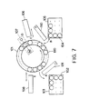
- Fig. 7 shows an example of an arrangement of the analysing unit of the structure described above, wherein a plurality of reaction vessels 100 are disposed, for example, in a circular constant temperature container 101 and intermittently moved in an arrowed direction by a drive source at a predetermined cycle.
- a sample storage unit 103 as a sampler or sample setting unit, in which a plurality of sample vessels 102 each containing a sample to be analyzed, is disposed at a position A around the container 101 and any arbitrary sample can be sucked by a sample supply nozzle 109 and supplied to the reaction vessel 100 positioned in confrontation therewith.
- a reagent storage unit 105 in which a plurality of reagent vessels 104 each containing a reagent to be reacted with a sample for analyzing a specific item thereof, is disposed at a position B and any arbitrary reagent can be sucked by a reagent supply nozzle 110 and supplied to the reaction vessel 100 positioned in confrontation therewith.
- a stirrer 106 for stirring a reacted solution in the reaction vessel 100 is disposed at a position C
- a light measurement unit 107 for measuring a reacted solution in the reaction vessel 100 moved intermittently by a colorimetric method is disposed at a position D
- a cleaning unit 108 for cleaning the reaction vessel 100 to which a measurement has been carried out is disposed at a position E.
- a sample to be analyzed is sucked from the sample vessel 102 by the sample supply nozzle 109 and supplied to the reaction vessel 100 at the position A in the state that the reaction vessel 100 is stopped, and a desired reagent to be reacted with the above sample is sucked from the reagent vessel 104 by the sample supply nozzle 110 and supplied to the reaction vessel 100 at the position B.
- the reaction vessel 100 at the position C is stirred by the stirrer 106 and then the reaction vessel 100 at the position D is measured by the measurement unit 107 to analyze a desired item.
- the reaction vessel 100 to which a measurement has been carried out is cleaned by the cleaning unit 108 at the position E, and thereafter, moved to the position A so that it is repeatedly subjected to a series of the operations as described above.
- this automatic chemical analysis system needs an initial operation for preparation for the above measuring operation, prior to the start of the actual measuring operation.
- the initial operation means such operations as those for moving the operation units such as the above sample supply nozzle 109 and reagent supply nozzle 110 to regulated positions so that a predetermined measuring operation can be carried out and to introduce medium liquids such as reagents and cleaning solution necessary for the measuring operation to the regulated positions, and the like.
- the content of the initial operation is predetermined prior to the initiation of the measurement and the initial operation is carried out on the basis of the predetermined content.
- the operation for introducing the above medium liquids to the regulated position is determined to have a content by which the measuring operation is not obstructed by taking the deteriorating characteristics of the reagents and the level lowering characteristics of the cleaning agent into consideration.
- the conventional automatic chemical analysis system has a problem that although the operation for moving the operation units to the regulated position is essential in the initial operation, the operation for introducing the medium liquids to the regulated position will waste solutions and time, depending upon the conditions of the measuring operation.
- a case, in which the measuring operation is repeated several times at intervals and the intervals have different periods of time, will be considered with respect to a reagent as an example. If the intervals have a short period of time, the reagent can be used several times because it is not deteriorated, whereas when the intervals have a long period of time, the reagent cannot be used several times because it is deteriorated. To cope with this problem, how many times a reagent is to be disposed in the midway of measurement is conventionally determined to cover the intervals having a long period of time by taking the worst conditions into consideration, and thus, there may cause a case where even a reagent which can be intrinsically used is disposed and wasted.
- a solution detection sensor is provided to check whether or not each reagent is effective according to the period of the intervals, this countermeasure is difficult to be performed because a maintenance of the sensor is necessary for preventing the sensor from being contaminated due to the nature of a solution. Further, an increase in cost involved by the provision of the sensor cannot be avoided. Further, although it may be contemplated that an operator determines whether or not each reagent is effective by observing it, this method imposes a burden on the operator and prevents the operator from being entirely devoted in an original measuring job.
- An object of the present invention is to substantially eliminate defects or drawbacks encounted in the prior art and to provide an automatic chemical analysis sytem and method capable of automatically changing the content of a predetermined initial operation in accordance with the elapsing of time for the execution of the measurement operation.
- an automatic chemical analysis sytem in which a sample to be analyzed is reacted with a reagent to measure a concentration of a specific composition in a mixed reaction solution, comprising:
- an automatic chemical analysis system in which a sample to be analyzed is reacted with a reagent to measure a consentration of a specific composition of a mixed reaction solution, comprising:
- the control means controls the executing unit in accordance with a present time (Tn) obtained from the time setting unit, an operation termination time (Te) of each of units constituting the analysis sytem and an operation elapsing time (Ts) preliminarily set to each of the units.
- Tn present time
- Te operation termination time
- Ts operation elapsing time
- the central control means includes a main control means operatively connected to the input unit and the time setting unit, an operation control means opertively connected to the main control means, the sample setting unit, the reagent unit, the reaction unit, and the cleaning unit, a memory means connected to the main control means, and a calculation means operatively connected to the main control means and the output unit.
- the operation control means may be comprised of an interface means.
- an automatic chemical analysis method performed by an automatic chemical analysis system in which a sample to be analyzed is reacted with a reagent to measure a concentration of a specific composition in a mixed reaction solution, comprising the steps of:
- the discrimination is carried out in accordance with a present time (Tn), an operation termination time (Te) of each of units constituting the analysis sytem and an operation elapsing time (Ts) preliminarily set to each of the units.
- Tn present time
- Te operation termination time
- Ts operation elapsing time
- a time elapsed from a preset time to a time at which the measurement operation is scheduled to be initiated is calculated prior to the start of the measurement operation, the content of the initial operation is automatically changed in accordance with the length of the elapsed time and the measurement operation is initiated after the execution of the initial operation.
- Fig. 1 is a schematic plan view of one example of an automatic chemical analysis system to which the present invention is applicable.
- the system generally comprises a sample setting unit as a sampler 24 into which a plurality of sample vessels 8 such as test tubes are accommodated, the sampler 24 having a circular outer contoure and being rotatable in arrowed directions, at least one reaction unit 26, two in the illustration, in which the sample fed from the sampler 24 is reacted, and a control unit 200 such as central processing unit (CPU) operatively connected to these units.
- the system may further includes a dilution line 25 for diluting the sample as occasion dimands.
- the system further includes a reagent setting unit 5 for supplying a reagent into a sample vessel 8a in the reaction unit 26, cleaning units for cleaning a sample suction probe, a reagent supply nozzle and the like at various operation stages, and a measurement unit 27, for example, utilizing light means.
- a reagent setting unit 5 for supplying a reagent into a sample vessel 8a in the reaction unit 26, cleaning units for cleaning a sample suction probe, a reagent supply nozzle and the like at various operation stages, and a measurement unit 27, for example, utilizing light means.
- Solutions or liquids such as treated in the reagent setting unit, the dilution line, the cleaning unit and the like are supplied or discharged by means of pump means which are operatively connected to the CPU 200 including a control unit 2 and an operation control unit 4 as interface means I/F.
- the reaction unit 26 includes a stirrer 30 and a cleaning means 31, and a constant temperature means 38 for maintaining a constant temperature is connected or incorporated to the reaction unit 26.
- the sample is supplied into the sample vessel 8 through a sample supply nozzle 18 and then sucked by a predetermined amount by a sampling arm 38 provided with a sample suction probe. This operation is monitored by a sensor 37.
- reference numeral 32 denotes a sampling pump
- 33 denotes a cleaning pump
- 34 denotes a buffer pump
- 35 denotes a sample supply pump.
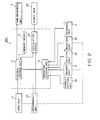
- Fig. 2 is a block diagram showing the automatic chemical analysis system of Fig. 1 as a block.
- the system comprises a CPU 200, an input unit 1 such as keyboard for inputting information or data into the CPU, and an output unit 22 such as display means or printer, and the system further comprises the sampler 24, the reagent setting unit 5, the reaction unit 26, the cleaning unit 6, the measurement unit 27, and a time measuring and setting means 7 connected to the CPU 200.
- the CPU 200 includes a control unit 2 connected to the input unit 2, an operation control unit 4 as interface means, for example, which is operatively connected to other units or means described above, a memory unit 3 and an operating or calculation means 23.
- the input unit 1 is for inputting conditions and data necessaary for performing a measuring operation and initial operation.
- the input information is inputted to the control unit 2 and the necessary information thereof is stored in the memory unit 3.
- the operation control unit 4 controls the reagent unit 5, a cleaning unit 6 and other units in response to commands from the control unit 2.
- Fig. 3 shows an arrangement of the reagent unit 5 by way of example composed of a reagent supply nozzle 19 for supplying a reagent to a reaction vessel 8a containing a sample reacting therewith, a reagent tube 9 connected to the nozzle 19 at one end thereof, a reagent pump 10 connected to other end of the reagent tube 9, an electromagnetic valve 11 incorporated to the reagent tube 9 adapted to supply the reagent, and a reagent bottle 12 stored in a refrigerator 13, for example.
- the reagent pump 10 When the reagent pump 10 is operated to suck the reagent in the state that the electromagnetic valve 11 is opened, the reagent is sucked from the reagent bottle 12, and when the reagent pump 10 is operated to discharge the reagent after the electromagnetic valve 11 has been closed, the sucked reagent is supplied to the reaction vessel 8a from the reagent supply nozzle 19 through the reagent tube 9.
- Fig. 4 shows an arrangement of the cleaning unit 6 by way of example composed of a cleaning bath 14 containing a cleaning liquid such as pure water or the like, a liquid discharge bath 15 in which the cleaning bath 14 is disposed, a probe 16 having one end immersed into the cleaning bath, a cleaning pump 17 for suking the pure water, and electromagnetic valve 21 for the pure water.
- the cleaning pump 17 When the cleaning pump 17 is operated to suck the pure water in the state that the electromagnetic valve 21 is opened, the pure water is sucked as shown by an arrow, and when the cleaning pump 17 is operated to discharge the pure water after the electromagnetic valve 21 has been closed, the sucked pure water is replenished to the cleaning bath 14.
- the time measuring and setting means 7 counts a present time which is inputted to the control unit 2 at all times.
- the control unit 2 manages when, how long and what kind of operation each unit carries out at all times and stores this information to the memory unit 3. Further, when a measuring operation is repeated several times at intervals, the control unit 2 detects the start of the operation of the reagent unit 5 and cleaning unit 6 in each measureing operation through the oepration control unit 4, reads out the time at the start of the operation from the time measuring and setting means 7, and stores the same to the memory unit 3 each time the measuring operation is carried out.
- the next operations of the reagent unit 5 and cleaning unit 6 are started in 3 hours and 10 minutes and 2 hours and 50 minutes from the termination of the previous operations, respectively, and thus there is a possibility that the reagent may be deteriorated because it is left for a time exceeding the allowable time of 3 hours, whereas the cleaning liquid has no problem because it can be used within the alowable time. Therefore, in this case, the initial operation additionally carries out an operation under the control of the control unit 2. Thereafter, a measuring operation is started.
- the next operations of the reagent unit 5 and cleaning unit 6 are started in 5 hours and 10 minutes and 4 hours and 50 minutes from the termination of the previous operations, respectively, and thus both of these periods of time exceed the above allowable times. Therefore, there is a possibility that the reagent may be deteriorated and it is also considered that the level of the cleaning liquid may be lowered below a regulated level. Therefore, in this case, the initial operation additionally carries out an operation for replacing the reagent and several times of preparatory operations for sucking a cleaning liquid for replenishment, and thereafter, a measuring operation is started. The above operations are automatically carried out in the same way as the above case.
- step S1 an operation such as measuring, cleaning or maintenance operation is instructed to be started and in accordance with this instruction, an initial operation is started in step S1, which will be described in detail hereinlatter with reference to Fig. 6.
- step S2 the main process such as for the above operation is performed.
- step S3 present time of every unit or means for executing the respective operations such as cleaning unit, pump means, measuring means or the like is measured by the time measuring and setting means 7 and the measured time is set and stored in the memory unit 3 of the CPU 200.
- step S4 After certain time elapses, it is discriminated whether or not the required operation is completed in step S4. In the case of NO, the process returns to the step S2, and in the case of YES, the operation is ended.
- the present time (Tn) is first obtained from the time measuring means 7 in step S1 a and the final operation termination times (Te) of the respective units and means are then obtained in step S1 b.
- infomations regarding preliminarily set operation elapsing times (Ts) of the respective units and means are taken out.
- step S1 e an instruction is made to carry out a basic operation 1 being the minimumly necessary initial opertion
- step S1f an instruction is made to carry out a basic operation 2 in step S1f, in which, in addition to the basic operation 1, an operation such as for replacing the reagent or making up the liquid such as water is performed for the preparation of performing of the correct operations.
- a time elapsed from the time at which a previous measuring operation is terminated to the time at which a next measuring operation is started is calculated prior to the start of the next measuring operation and the content of an initial operation is automatically changed in accordance with the length of the elapsed time before the measuting operation is started, whereby a time necessary for the initial operation can be shortened and a measurement can be started at once upon receiving a measurement start command. Further, when the above elapsed time is short and medium liquids such as a reagent are less wasted.
Landscapes
- Chemical & Material Sciences (AREA)
- Physics & Mathematics (AREA)
- Health & Medical Sciences (AREA)
- Life Sciences & Earth Sciences (AREA)
- Analytical Chemistry (AREA)
- Biochemistry (AREA)
- General Health & Medical Sciences (AREA)
- General Physics & Mathematics (AREA)
- Immunology (AREA)
- Pathology (AREA)
- Chemical Kinetics & Catalysis (AREA)
- Automatic Analysis And Handling Materials Therefor (AREA)
Applications Claiming Priority (2)
| Application Number | Priority Date | Filing Date | Title |
|---|---|---|---|
| JP3061670A JP2944772B2 (ja) | 1991-03-26 | 1991-03-26 | 自動化学分析装置 |
| JP61670/91 | 1991-03-26 |
Publications (2)
| Publication Number | Publication Date |
|---|---|
| EP0506024A2 true EP0506024A2 (de) | 1992-09-30 |
| EP0506024A3 EP0506024A3 (en) | 1993-01-20 |
Family
ID=13177906
Family Applications (1)
| Application Number | Title | Priority Date | Filing Date |
|---|---|---|---|
| EP19920105151 Ceased EP0506024A3 (en) | 1991-03-26 | 1992-03-25 | Automatic chemical analysis system and automatic chemical analysis method |
Country Status (2)
| Country | Link |
|---|---|
| EP (1) | EP0506024A3 (de) |
| JP (1) | JP2944772B2 (de) |
Cited By (1)
| Publication number | Priority date | Publication date | Assignee | Title |
|---|---|---|---|---|
| CN102667492A (zh) * | 2009-12-21 | 2012-09-12 | 株式会社日立高新技术 | 免疫分析装置 |
Families Citing this family (4)
| Publication number | Priority date | Publication date | Assignee | Title |
|---|---|---|---|---|
| JP4586302B2 (ja) * | 2001-05-28 | 2010-11-24 | 三浦工業株式会社 | 溶存酸素濃度の測定方法 |
| JP5517160B2 (ja) * | 2010-06-25 | 2014-06-11 | 株式会社日立ハイテクノロジーズ | 自動分析装置 |
| JP5805486B2 (ja) * | 2011-09-30 | 2015-11-04 | シスメックス株式会社 | 検体分析装置 |
| JP6121668B2 (ja) * | 2012-08-31 | 2017-04-26 | 東芝メディカルシステムズ株式会社 | 自動分析装置 |
Family Cites Families (1)
| Publication number | Priority date | Publication date | Assignee | Title |
|---|---|---|---|---|
| JP2595063B2 (ja) * | 1988-09-16 | 1997-03-26 | 株式会社日立製作所 | 自動分析装置 |
-
1991
- 1991-03-26 JP JP3061670A patent/JP2944772B2/ja not_active Expired - Fee Related
-
1992
- 1992-03-25 EP EP19920105151 patent/EP0506024A3/en not_active Ceased
Cited By (1)
| Publication number | Priority date | Publication date | Assignee | Title |
|---|---|---|---|---|
| CN102667492A (zh) * | 2009-12-21 | 2012-09-12 | 株式会社日立高新技术 | 免疫分析装置 |
Also Published As
| Publication number | Publication date |
|---|---|
| EP0506024A3 (en) | 1993-01-20 |
| JPH04295763A (ja) | 1992-10-20 |
| JP2944772B2 (ja) | 1999-09-06 |
Similar Documents
| Publication | Publication Date | Title |
|---|---|---|
| JP7193564B2 (ja) | 自動分析装置及び自動分析方法 | |
| JP3990944B2 (ja) | 自動分析装置 | |
| US8940231B2 (en) | Measuring equipment and measuring method using cartridge container, and program recording medium | |
| US5434083A (en) | Method and apparatus for automatically analyzing a plurality of test items | |
| EP1895307A1 (de) | Automatisiertes Analysegerät | |
| JP2927082B2 (ja) | 液体サンプル用分析方法および分析装置 | |
| US6579717B1 (en) | Specific solution handling method for calibration and quality control by automatic analytical apparatus | |
| JP2525063B2 (ja) | 自動分析方法 | |
| EP2835649A1 (de) | Automatische analysevorrichtung | |
| JP3271741B2 (ja) | 自動分析方法及び装置 | |
| EP1649351A2 (de) | Nach funktion in einem automatischen klinischen analysierer segmentiertes bedienerschnittstellenmodul | |
| EP3745140B1 (de) | Automatisierter analysator und verfahren zur steuerung des automatisierten analysators | |
| JP7105530B2 (ja) | 自動分析装置および自動分析装置におけるメンテナンスガイド方法 | |
| JP6928712B2 (ja) | 自動分析装置 | |
| JPH0666813A (ja) | 自動分析装置 | |
| EP0506024A2 (de) | Vorrichtung und Verfahren für automatische chemische Analysen | |
| JP3204737B2 (ja) | 自動化学分析装置 | |
| CN112585473A (zh) | 自动分析装置 | |
| JP2815433B2 (ja) | 自動分析装置 | |
| JP7174066B2 (ja) | 自動分析装置 | |
| JPH0886784A (ja) | 自動分析装置 | |
| JP2557869B2 (ja) | 自動化学分析装置 | |
| US11175302B2 (en) | Apparatus and method for automated analysis | |
| JP2016133475A (ja) | 自動分析装置及び自動分析方法 | |
| WO2024042801A1 (ja) | 自動分析装置とその制御方法 |
Legal Events
| Date | Code | Title | Description |
|---|---|---|---|
| PUAI | Public reference made under article 153(3) epc to a published international application that has entered the european phase |
Free format text: ORIGINAL CODE: 0009012 |
|
| 17P | Request for examination filed |
Effective date: 19920325 |
|
| AK | Designated contracting states |
Kind code of ref document: A2 Designated state(s): DE |
|
| PUAL | Search report despatched |
Free format text: ORIGINAL CODE: 0009013 |
|
| AK | Designated contracting states |
Kind code of ref document: A3 Designated state(s): DE |
|
| 17Q | First examination report despatched |
Effective date: 19950410 |
|
| STAA | Information on the status of an ep patent application or granted ep patent |
Free format text: STATUS: THE APPLICATION HAS BEEN REFUSED |
|
| 18R | Application refused |
Effective date: 19951016 |