EP0505704B1 - Dichteinrichtung für zylindrische Öffnungen, insbesondere zum Verschliessen von Pumpenstutzen im Innenraum von Kernreaktorbehältern - Google Patents
Dichteinrichtung für zylindrische Öffnungen, insbesondere zum Verschliessen von Pumpenstutzen im Innenraum von Kernreaktorbehältern Download PDFInfo
- Publication number
- EP0505704B1 EP0505704B1 EP92102119A EP92102119A EP0505704B1 EP 0505704 B1 EP0505704 B1 EP 0505704B1 EP 92102119 A EP92102119 A EP 92102119A EP 92102119 A EP92102119 A EP 92102119A EP 0505704 B1 EP0505704 B1 EP 0505704B1
- Authority
- EP
- European Patent Office
- Prior art keywords
- sealing
- clamping
- unlocking
- sleeve
- pawls
- Prior art date
- Legal status (The legal status is an assumption and is not a legal conclusion. Google has not performed a legal analysis and makes no representation as to the accuracy of the status listed.)
- Expired - Lifetime
Links
- 238000007789 sealing Methods 0.000 title claims description 84
- 238000006073 displacement reaction Methods 0.000 claims description 5
- 241000209035 Ilex Species 0.000 description 5
- 239000007788 liquid Substances 0.000 description 4
- 230000008878 coupling Effects 0.000 description 3
- 238000010168 coupling process Methods 0.000 description 3
- 238000005859 coupling reaction Methods 0.000 description 3
- 238000000034 method Methods 0.000 description 2
- 125000006850 spacer group Chemical group 0.000 description 2
- 241000196324 Embryophyta Species 0.000 description 1
- 239000006096 absorbing agent Substances 0.000 description 1
- 238000006243 chemical reaction Methods 0.000 description 1
- 239000002826 coolant Substances 0.000 description 1
- 230000000694 effects Effects 0.000 description 1
- 230000005484 gravity Effects 0.000 description 1
- 230000002706 hydrostatic effect Effects 0.000 description 1
- 230000003993 interaction Effects 0.000 description 1
- 238000012423 maintenance Methods 0.000 description 1
- 238000000926 separation method Methods 0.000 description 1
- 230000035939 shock Effects 0.000 description 1
Images




Classifications
-
- G—PHYSICS
- G21—NUCLEAR PHYSICS; NUCLEAR ENGINEERING
- G21C—NUCLEAR REACTORS
- G21C13/00—Pressure vessels; Containment vessels; Containment in general
- G21C13/02—Details
- G21C13/06—Sealing-plugs
- G21C13/067—Sealing-plugs for tubes, e.g. standpipes; Locking devices for plugs
-
- F—MECHANICAL ENGINEERING; LIGHTING; HEATING; WEAPONS; BLASTING
- F16—ENGINEERING ELEMENTS AND UNITS; GENERAL MEASURES FOR PRODUCING AND MAINTAINING EFFECTIVE FUNCTIONING OF MACHINES OR INSTALLATIONS; THERMAL INSULATION IN GENERAL
- F16L—PIPES; JOINTS OR FITTINGS FOR PIPES; SUPPORTS FOR PIPES, CABLES OR PROTECTIVE TUBING; MEANS FOR THERMAL INSULATION IN GENERAL
- F16L55/00—Devices or appurtenances for use in, or in connection with, pipes or pipe systems
- F16L55/10—Means for stopping flow in pipes or hoses
- F16L55/12—Means for stopping flow in pipes or hoses by introducing into the pipe a member expandable in situ
- F16L55/128—Means for stopping flow in pipes or hoses by introducing into the pipe a member expandable in situ introduced axially into the pipe or hose
- F16L55/132—Means for stopping flow in pipes or hoses by introducing into the pipe a member expandable in situ introduced axially into the pipe or hose the closure device being a plug fixed by radially deforming the packing
-
- Y—GENERAL TAGGING OF NEW TECHNOLOGICAL DEVELOPMENTS; GENERAL TAGGING OF CROSS-SECTIONAL TECHNOLOGIES SPANNING OVER SEVERAL SECTIONS OF THE IPC; TECHNICAL SUBJECTS COVERED BY FORMER USPC CROSS-REFERENCE ART COLLECTIONS [XRACs] AND DIGESTS
- Y02—TECHNOLOGIES OR APPLICATIONS FOR MITIGATION OR ADAPTATION AGAINST CLIMATE CHANGE
- Y02E—REDUCTION OF GREENHOUSE GAS [GHG] EMISSIONS, RELATED TO ENERGY GENERATION, TRANSMISSION OR DISTRIBUTION
- Y02E30/00—Energy generation of nuclear origin
- Y02E30/30—Nuclear fission reactors
Definitions
- the invention relates to a sealing device for cylindrical openings, in particular for closing pump connections in the interior of nuclear reactor vessels, according to the preamble of claim 1.
- Such sealing devices are preferably used in nuclear plants in connection with control and maintenance work, in particular for sealing or separating liquid circuits in reactor vessels.
- the particular suitability for this results from their remote control, which excludes hazards for the operating personnel, from a reliable sealing of the opening in question even when the setting tool is separate from the sealing insert and from the possibility of also being able to remove the sealing inserts with the setting tool.
- a removable and remountable sealing device for pipes in particular for sealing the main coolant nozzle of a reactor pressure vessel, which consists of a cylindrical sealing insert with at least one sealing ring and an operating device for transporting, inserting and removing the sealing insert.
- an operating device for transporting, inserting and removing the sealing insert.
- To receive the sealing insert from the operating device it is inserted on roller arms into the interior of the two coaxially arranged, axially displaceable, annular sealing body parts.
- the connection between the sealing insert and the operating device is made by moving locking bolts radially outward on a link plate of the operating device and engaging in openings in the sealing insert.
- a disadvantage of the known solution is that only pipelines of larger diameter can be sealed due to the space requirement of the operating device which can be inserted into the interior of the sealing insert.
- connection of the sealing insert and the operating device via bolts engaging in openings requires an exact positioning of the components in their rotational position, which makes coupling of the sealing insert considerably more difficult, particularly in the case of remote control and in the underwater area.
- the invention has for its object to design a sealing device of the type mentioned so that even cylindrical openings of smaller diameters can be reliably sealed and the seating of the sealing insert by the setting tool is possible regardless of the rotational position.
- the advantages achieved by the invention are that the sealing device enables reliable sealing of cylindrical openings, even of smaller diameters, and that the sealing insert and setting tool can be connected in any randomly occurring rotational position of the components.
- An embodiment of the invention according to the features of claims 2 and 3 is provided for transmitting large clamping forces which allow a high degree of tightness to be achieved, but which require an undivided clamping anchor.
- the embodiment of the invention is based on the features of the claim 5 provided.
- a transport of the sealing insert on the sleeve supported on the bearing blocks is always carried out in the unlocked state and thus in a relaxed sealing ring which is not loaded by the inherent weight of the outer sealing body part, which enables the sealing insert to be inserted into the opening to be sealed without problems .
- the sealing insert A has a plug core 1 and a plug jacket 2 arranged coaxially to the latter, between whose opposing shoulder surfaces there is a sealing ring 3.
- the plug core 1 is connected to a tension anchor 4 by screws arranged on the circumference of the tension anchor flange 4a.
- the plug casing 2 is connected to an annular disk 5 which has a seal 6 on the sealing ring side, the position of which is fixed by a retaining ring 7 which engages in recesses in the seal 6 and the annular disk 5.
- bearing blocks 8 are screwed to the same.
- a sleeve 12 is arranged coaxially to the tension anchor 4 and displaceable thereon.
- the sleeve 12 consists of three sliding pieces 12a which are screwed into a rigid body via an upper and a lower flange 12b, 12c.
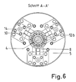
- the flanges 12b and 12c are designed radially in two parts so that the assembly of all parts of the sleeve 12 on the tension anchor 4 is possible (Fig. 3, 4, 6).
- the sleeve 12 has axially arranged elongated holes 12d, through which the projections 4b of the tension anchor 4 extend radially outward.
- the displacement path of the sleeve 12 is limited by the positioning of the bearing blocks 8, the spacer ring 13 and the stops 8a located on the bearing blocks 8.
- the sealing insert A can expediently be transported without any force being exerted on the sealing ring 3 by making this even closer Setting tool B to be described engages the upper flange 12b of the sleeve 12 and is supported on the bearing blocks 8.
- the setting tool B used for handling the sealing insert A is shown in FIGS. 8 and 9.
- housing-forming components it comprises a centering ring 20, an unlocking cylinder 21, an intermediate ring 22, a tensioning cylinder 23 and a bell 24, all of which are connected to one another by screwing.
- the clamping cylinder 23 has a clamping piston 23a designed as a hollow cylinder, into which a hollow cylindrical piston rod 23b with collar 23c is screwed. Two bolts 23d are attached to the piston rod 23b and carry radially pivotable pawls 23e.
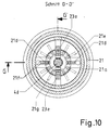
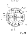
- the unlocking piston 21a of the unlocking cylinder 21 is provided with a support body 21b on which unlocking hooks 21d are radially pivotably mounted on two bolts 21c. Furthermore, an annular profile body 21e is flanged to the unlocking piston 21a, the outer circumference of which has guideways 21f for the tensioning pawls 23e and the unlocking hooks 21d and on the inwardly directed guide ribs 21g for centering reception of the tension anchor 4 of the sealing insert A (FIG. 10).
- the unlocking hooks 21d each carry a pivotable flap 21h which bears against the circumference of the flange 12b of the sleeve 12 when the unlocking hooks 21d are pivoted inward. If the flange 12b is completely gripped behind by the release hooks 21d, the flap 21h engages over the flange 12b.
- control cylinder 25 which axially displaces a control slide 25b provided with cams 25a in the interior of the piston rod 23b, the tensioning pawls 23e and the unlocking hooks 21d on their lever ends 23f, 21i and control cams 23g, 21k on the control slide 25b sliding, radially pivoted.
- An anti-rotation device for the pawls 23e opposite the control slide 25b is provided by screw bolts 23h located in the piston rod 23b, which engage in axial slots 25c of the control slide 25b.
- the bell 24 also has a lifting eye 26 and hydraulic couplings, not shown, which connect hydraulic hoses emanating from an operating panel for actuating the tensioning cylinder 23, the unlocking cylinder 21 and the control cylinder 25 to hydraulic lines arranged on the setting tool B.
- the hydraulic lines are located in grooves on the surface of the setting tool B, which protects them from damage and a smooth tool surface.
- sealing insert A and setting tool B for the case of sealing a pump nozzle 15 arranged vertically in a liquid-filled container is to be explained in more detail below.
- the setting tool B hanging from the load eye 26 is lowered onto the relaxed sealing insert A located in a storage rack with the tension anchor 4 pointing upwards.
- the unlocking hooks 21d and the pawls 23e of the setting tool B, actuated by the control slide 25b, are pivoted outwards.
- the head 4d of the tensioning anchor 4 which dips into the guide ribs 21g of the profile body 21e causes the setting tool B to be pre-centered.
- the final centering is achieved by the centering ring 22 being seated on the bearing blocks 8 and the radial contact with the diameter of the centering bolts 14 (FIG. 8) .
- the unlocking piston 21a In preparation for the sealing process, the unlocking piston 21a is moved downward.
- the sleeve 12 follows this movement under the effect of gravity or by the pressure exerted by the spring-loaded flaps 21h arranged on the unlocking hooks 21d on the upper flange 12b of the sleeve 12. This enables a radially inward pivoting of the pawls 10 when the tension anchor 4 is displaced in the tensioning direction s.
- the tensioning armature 4 is moved in the tensioning direction s by the upward stroke of the tensioning piston 23a, the centering ring 20 of the setting tool B being supported on the bearing blocks 8.
- the clamping force transmitted to the sealing ring 3 leads to a sealing surface pressure of the outer circumference of the sealing ring 3 on the inner wall of the connecting piece.
- a reaction force which is opposite to the tensioning direction s of the tensioning armature 4 is transmitted from the sealing ring 3 to the axially acting seal 6, whereby a higher degree of tightness of the seal 6 can be achieved than is the case with exclusively hydrostatic force.
- the tensioning piston 23a can now be moved downward, since the tensioning state of the sealing insert A is maintained by locking by means of the pawls 10.
- the unlocking hooks 21d and pawls 23e are pivoted outwards.
- the setting tool B can then be raised and thus separated from the sealing insert A.
- the clamping piston 23a For removal of the sealing insert A from the pump connection 15, after the lowering and centering of the setting tool B already described and the pivoting in of the release hooks 21d and clamping pawls 23e, the clamping piston 23a has to be moved so far in the clamping direction s that the pawls 10 are relieved. As a result of the upward movement of the unlocking piston 21a, the pawls 10 on the sleeve 12 are pivoted outwards. The sealing insert A thus unlocked is relaxed when the tensioning piston 23a moves downward and is removed from the pump connector 15 on the sleeve 12. The separation of the sealing insert A from the setting tool B is possible after the downward displacement of the sleeve 12 and the pivoting out of the unlocking hooks 21d and the clamping pawls 23e.
- the use of the sealing device is not limited to liquids.
- the sealing device is also suitable for sealing or separating gaseous media.
Landscapes
- Engineering & Computer Science (AREA)
- General Engineering & Computer Science (AREA)
- Physics & Mathematics (AREA)
- Mechanical Engineering (AREA)
- Plasma & Fusion (AREA)
- High Energy & Nuclear Physics (AREA)
- Pressure Vessels And Lids Thereof (AREA)
- Structures Of Non-Positive Displacement Pumps (AREA)
Applications Claiming Priority (2)
| Application Number | Priority Date | Filing Date | Title |
|---|---|---|---|
| DE4108055A DE4108055C1 (OSRAM) | 1991-03-13 | 1991-03-13 | |
| DE4108055 | 1991-03-13 |
Publications (2)
| Publication Number | Publication Date |
|---|---|
| EP0505704A1 EP0505704A1 (de) | 1992-09-30 |
| EP0505704B1 true EP0505704B1 (de) | 1995-07-12 |
Family
ID=6427149
Family Applications (1)
| Application Number | Title | Priority Date | Filing Date |
|---|---|---|---|
| EP92102119A Expired - Lifetime EP0505704B1 (de) | 1991-03-13 | 1992-02-08 | Dichteinrichtung für zylindrische Öffnungen, insbesondere zum Verschliessen von Pumpenstutzen im Innenraum von Kernreaktorbehältern |
Country Status (3)
| Country | Link |
|---|---|
| US (1) | US5255294A (OSRAM) |
| EP (1) | EP0505704B1 (OSRAM) |
| DE (2) | DE4108055C1 (OSRAM) |
Cited By (1)
| Publication number | Priority date | Publication date | Assignee | Title |
|---|---|---|---|---|
| CN105402404A (zh) * | 2015-12-22 | 2016-03-16 | 中车戚墅堰机车车辆工艺研究所有限公司 | 一种涨紧式内孔密封机构及应用 |
Families Citing this family (13)
| Publication number | Priority date | Publication date | Assignee | Title |
|---|---|---|---|---|
| US5640999A (en) * | 1995-06-07 | 1997-06-24 | Dover Corporation | Venting cap for fill pipe |
| US5752814A (en) * | 1995-09-26 | 1998-05-19 | Starks; Jimmy A. | Plunger and seal for well pump |
| DE10000196B4 (de) * | 2000-01-05 | 2013-10-10 | Sartorius Stedim Biotech Gmbh | Verbesserte Crossflow-Filtrationseinheit |
| US6732762B2 (en) * | 2001-01-12 | 2004-05-11 | Larry R. Russell | Pressure-containing plug for a tubular passageway |
| IES20020089A2 (en) * | 2002-02-08 | 2003-08-20 | Carsphairn Ltd | An improved pipeline isolation tool |
| RU2252462C2 (ru) * | 2003-06-27 | 2005-05-20 | Федеральное государственное унитарное предприятие "Научно-исследовательский и конструкторский институт энерготехники им. Н.А. Доллежаля" | Верхнее защитное перекрытие ядерного реактора с жидкометаллическим теплоносителем |
| NO320256B1 (no) * | 2003-12-05 | 2005-11-14 | Plugging Specialists Int | Plugg med hydraulisk sylinder og hydraulisk sylinder |
| US7134454B2 (en) * | 2004-12-27 | 2006-11-14 | Alain Montminy | Cap for blocking a pipe |
| RU2281570C1 (ru) * | 2005-01-11 | 2006-08-10 | Федеральное государственное унитарное предприятие "Научно-исследовательский и конструкторский институт энерготехники им. Н.А. Доллежаля" | Верхнее защитное перекрытие ядерного реактора с жидкометаллическим теплоносителем |
| RU2359347C2 (ru) * | 2007-08-02 | 2009-06-20 | Открытое акционерное общество "Центральное конструкторское бюро машиностроения" (ОАО "ЦКМБ") | Кольцо опорное многофункциональное |
| CN105090673A (zh) * | 2014-05-12 | 2015-11-25 | 中国北车集团大同电力机车有限责任公司 | 对钢管的深孔中部进行截断密封的装置和方法 |
| CN108302251B (zh) * | 2018-01-24 | 2020-06-02 | 湖州市政工程有限公司 | 一种基于杠杆传动的市政施工用的管线支架 |
| CN109458515B (zh) * | 2018-12-07 | 2024-05-03 | 中车西安车辆有限公司 | 一种取样管路气密封堵装置及方法 |
Family Cites Families (4)
| Publication number | Priority date | Publication date | Assignee | Title |
|---|---|---|---|---|
| GB911758A (en) * | 1958-12-10 | 1962-11-28 | Rolls Royce | Improvements in or relating to remote control handling apparatus for sealing pipes with plug and seal devices |
| FR91120E (fr) * | 1962-09-03 | 1968-04-19 | Commissariat Energie Atomique | Perfectionnements apportés aux dispositifs du genre de ceux pour le verrouillage mécanique des bouchons de canaux de réacteurs atomiques |
| US4262702A (en) * | 1979-12-20 | 1981-04-21 | Halliburton Company | Conductor pipe plug |
| DE3228802C2 (de) * | 1982-08-02 | 1986-08-28 | Kraftwerk Union AG, 4330 Mülheim | De- und remontable Abdichteinrichtung und ein Verfahren zur Vorbereitung der Abdichtung von Rohrleitungen, insbesondere der Hauptkühlmittelstutzen eines Reaktordruckbehälters |
-
1991
- 1991-03-13 DE DE4108055A patent/DE4108055C1/de not_active Expired - Lifetime
-
1992
- 1992-02-08 DE DE59202837T patent/DE59202837D1/de not_active Expired - Fee Related
- 1992-02-08 EP EP92102119A patent/EP0505704B1/de not_active Expired - Lifetime
- 1992-03-12 US US07/850,437 patent/US5255294A/en not_active Expired - Fee Related
Cited By (1)
| Publication number | Priority date | Publication date | Assignee | Title |
|---|---|---|---|---|
| CN105402404A (zh) * | 2015-12-22 | 2016-03-16 | 中车戚墅堰机车车辆工艺研究所有限公司 | 一种涨紧式内孔密封机构及应用 |
Also Published As
| Publication number | Publication date |
|---|---|
| EP0505704A1 (de) | 1992-09-30 |
| US5255294A (en) | 1993-10-19 |
| DE4108055C1 (OSRAM) | 1992-07-30 |
| DE59202837D1 (de) | 1995-08-17 |
Similar Documents
| Publication | Publication Date | Title |
|---|---|---|
| DE4108055C1 (OSRAM) | ||
| DE69506249T2 (de) | Verbesserte schnell montierbare mutter | |
| DE2540722C2 (de) | Doppeldeckel zum Verschließen von zwei aneinander anschließbare Öffnungen | |
| EP0859185B1 (de) | Anordnung zum Verbinden zweier rohrförmiger Elemente | |
| DE2059443B2 (de) | Zerbrechbare leitungskupplung | |
| EP0855243A2 (de) | Haltevorrichtung insbesondere für ein Werkstück | |
| DE3808644C1 (OSRAM) | ||
| DE2616189C2 (de) | Steigleitung für einen gelenkigen Aufbau für die Tiefwassererdölgewinnung | |
| DE2753667C2 (de) | Schnellkupplung, insbesondere für eine Betankungsleitung | |
| DE3524477A1 (de) | Umschaltbare mechanische kupplung | |
| DE4013228C1 (OSRAM) | ||
| DE1650005B1 (de) | Abreisskupplung fuer unter Druck stehende Behaelter mit je einem mit einem Behaelter verbundenen Kupplungsteil | |
| DE3208687C2 (de) | Hilfsvorrichtung zum Verspannen von Abfangkeilen in einem Bohrlochkopf und entsprechend ausgebildeter Bohrlochkopf-Aufbau | |
| EP2256395B1 (de) | Flanschelement | |
| DE2263195B2 (de) | Fangkeilanordnung für Bohrlochwerkzeuge | |
| DE2428847B2 (de) | Schraubenspannvorrichtung zum oeffnen und schliessen des deckels eines reaktorkessels | |
| DE2359163A1 (de) | Greifvorrichtung fuer langgestreckte koerper, die in aufnahmeoeffnungen eingesetzt und aus diesen herausgezogen werden sollen, insbesondere fuer brennelemente und regelstaebe in einem kernreaktor | |
| EP0154934A1 (de) | Schnellverschlusskupplung | |
| EP4244491B1 (de) | Verbindungsanordnung | |
| EP3492422A1 (de) | Hebevorrichtung und verfahren zum heben einer schweren komponente einer windenergieanlage | |
| DE873473C (de) | Verschluss | |
| DE19913171B4 (de) | Einrichtung zur stoßfreien Kopplung von Konstruktionselementen | |
| DE3146829C2 (de) | Innenbefahrvorrichtung für Großbehälter | |
| DE10158711A1 (de) | Vorrichtung zur lösbaren Verriegelung der Walzenzapfen mit einer, auf diese auf- und abschiebbaren Antriebskupplungsmuffe | |
| DE2337778C3 (de) | Rohrhängevorrichtung, Setz- und Ziehwerkzeug |
Legal Events
| Date | Code | Title | Description |
|---|---|---|---|
| PUAI | Public reference made under article 153(3) epc to a published international application that has entered the european phase |
Free format text: ORIGINAL CODE: 0009012 |
|
| AK | Designated contracting states |
Kind code of ref document: A1 Designated state(s): BE CH DE FR GB LI SE |
|
| 17P | Request for examination filed |
Effective date: 19921026 |
|
| 17Q | First examination report despatched |
Effective date: 19940429 |
|
| GRAA | (expected) grant |
Free format text: ORIGINAL CODE: 0009210 |
|
| AK | Designated contracting states |
Kind code of ref document: B1 Designated state(s): BE CH DE FR GB LI SE |
|
| PG25 | Lapsed in a contracting state [announced via postgrant information from national office to epo] |
Ref country code: GB Effective date: 19950712 Ref country code: FR Effective date: 19950712 |
|
| REF | Corresponds to: |
Ref document number: 59202837 Country of ref document: DE Date of ref document: 19950817 |
|
| PG25 | Lapsed in a contracting state [announced via postgrant information from national office to epo] |
Ref country code: SE Effective date: 19951012 |
|
| EN | Fr: translation not filed | ||
| PGFP | Annual fee paid to national office [announced via postgrant information from national office to epo] |
Ref country code: BE Payment date: 19960116 Year of fee payment: 5 |
|
| GBV | Gb: ep patent (uk) treated as always having been void in accordance with gb section 77(7)/1977 [no translation filed] |
Effective date: 19950712 |
|
| PGFP | Annual fee paid to national office [announced via postgrant information from national office to epo] |
Ref country code: CH Payment date: 19960126 Year of fee payment: 5 |
|
| PLBE | No opposition filed within time limit |
Free format text: ORIGINAL CODE: 0009261 |
|
| STAA | Information on the status of an ep patent application or granted ep patent |
Free format text: STATUS: NO OPPOSITION FILED WITHIN TIME LIMIT |
|
| 26N | No opposition filed | ||
| PG25 | Lapsed in a contracting state [announced via postgrant information from national office to epo] |
Ref country code: LI Effective date: 19970228 Ref country code: CH Effective date: 19970228 Ref country code: BE Effective date: 19970228 |
|
| BERE | Be: lapsed |
Owner name: THYSSEN INDUSTRIE A.G. Effective date: 19970228 |
|
| REG | Reference to a national code |
Ref country code: CH Ref legal event code: PL |
|
| PGFP | Annual fee paid to national office [announced via postgrant information from national office to epo] |
Ref country code: DE Payment date: 19980123 Year of fee payment: 7 |
|
| PG25 | Lapsed in a contracting state [announced via postgrant information from national office to epo] |
Ref country code: DE Free format text: LAPSE BECAUSE OF NON-PAYMENT OF DUE FEES Effective date: 19991201 |