EP0505643B1 - Mehrzweckübersetzungsgetriebe für ein Fahrrad - Google Patents
Mehrzweckübersetzungsgetriebe für ein Fahrrad Download PDFInfo
- Publication number
- EP0505643B1 EP0505643B1 EP91310086A EP91310086A EP0505643B1 EP 0505643 B1 EP0505643 B1 EP 0505643B1 EP 91310086 A EP91310086 A EP 91310086A EP 91310086 A EP91310086 A EP 91310086A EP 0505643 B1 EP0505643 B1 EP 0505643B1
- Authority
- EP
- European Patent Office
- Prior art keywords
- wheel
- wheels
- reciprocating
- bottom bracket
- cranks
- Prior art date
- Legal status (The legal status is an assumption and is not a legal conclusion. Google has not performed a legal analysis and makes no representation as to the accuracy of the status listed.)
- Expired - Lifetime
Links
Images

Classifications
-
- B—PERFORMING OPERATIONS; TRANSPORTING
- B62—LAND VEHICLES FOR TRAVELLING OTHERWISE THAN ON RAILS
- B62M—RIDER PROPULSION OF WHEELED VEHICLES OR SLEDGES; POWERED PROPULSION OF SLEDGES OR SINGLE-TRACK CYCLES; TRANSMISSIONS SPECIALLY ADAPTED FOR SUCH VEHICLES
- B62M11/00—Transmissions characterised by the use of interengaging toothed wheels or frictionally-engaging wheels
-
- B—PERFORMING OPERATIONS; TRANSPORTING
- B62—LAND VEHICLES FOR TRAVELLING OTHERWISE THAN ON RAILS
- B62M—RIDER PROPULSION OF WHEELED VEHICLES OR SLEDGES; POWERED PROPULSION OF SLEDGES OR SINGLE-TRACK CYCLES; TRANSMISSIONS SPECIALLY ADAPTED FOR SUCH VEHICLES
- B62M1/00—Rider propulsion of wheeled vehicles
- B62M1/24—Rider propulsion of wheeled vehicles with reciprocating levers, e.g. foot levers
- B62M1/28—Rider propulsion of wheeled vehicles with reciprocating levers, e.g. foot levers characterised by the use of flexible drive members, e.g. chains
-
- B—PERFORMING OPERATIONS; TRANSPORTING
- B62—LAND VEHICLES FOR TRAVELLING OTHERWISE THAN ON RAILS
- B62M—RIDER PROPULSION OF WHEELED VEHICLES OR SLEDGES; POWERED PROPULSION OF SLEDGES OR SINGLE-TRACK CYCLES; TRANSMISSIONS SPECIALLY ADAPTED FOR SUCH VEHICLES
- B62M1/00—Rider propulsion of wheeled vehicles
- B62M1/24—Rider propulsion of wheeled vehicles with reciprocating levers, e.g. foot levers
-
- B—PERFORMING OPERATIONS; TRANSPORTING
- B62—LAND VEHICLES FOR TRAVELLING OTHERWISE THAN ON RAILS
- B62M—RIDER PROPULSION OF WHEELED VEHICLES OR SLEDGES; POWERED PROPULSION OF SLEDGES OR SINGLE-TRACK CYCLES; TRANSMISSIONS SPECIALLY ADAPTED FOR SUCH VEHICLES
- B62M3/00—Construction of cranks operated by hand or foot
- B62M3/003—Combination of crank axles and bearings housed in the bottom bracket
-
- Y—GENERAL TAGGING OF NEW TECHNOLOGICAL DEVELOPMENTS; GENERAL TAGGING OF CROSS-SECTIONAL TECHNOLOGIES SPANNING OVER SEVERAL SECTIONS OF THE IPC; TECHNICAL SUBJECTS COVERED BY FORMER USPC CROSS-REFERENCE ART COLLECTIONS [XRACs] AND DIGESTS
- Y10—TECHNICAL SUBJECTS COVERED BY FORMER USPC
- Y10T—TECHNICAL SUBJECTS COVERED BY FORMER US CLASSIFICATION
- Y10T74/00—Machine element or mechanism
- Y10T74/15—Intermittent grip type mechanical movement
- Y10T74/1526—Oscillation or reciprocation to intermittent unidirectional motion
- Y10T74/1553—Lever actuator
- Y10T74/1555—Rotary driven element
- Y10T74/1556—Multiple acting
-
- Y—GENERAL TAGGING OF NEW TECHNOLOGICAL DEVELOPMENTS; GENERAL TAGGING OF CROSS-SECTIONAL TECHNOLOGIES SPANNING OVER SEVERAL SECTIONS OF THE IPC; TECHNICAL SUBJECTS COVERED BY FORMER USPC CROSS-REFERENCE ART COLLECTIONS [XRACs] AND DIGESTS
- Y10—TECHNICAL SUBJECTS COVERED BY FORMER USPC
- Y10T—TECHNICAL SUBJECTS COVERED BY FORMER US CLASSIFICATION
- Y10T74/00—Machine element or mechanism
- Y10T74/21—Elements
- Y10T74/2164—Cranks and pedals
- Y10T74/2165—Cranks and pedals with attached gear
Definitions
- the present invention relates to transmission mechanisms for bicycles and relates more particularly to a multipurpose transmission mechanism for a bicycle which can be controlled to propel a bicycle or the like by foot pedals through crank or lever transmission or, alternatively through crank and lever transmission.
- crank-driven type of power transmission mechanism In regular bicycles, tricycles or stationary bicycles, power transmission is generally made through rotary type of crank motion or reciprocating type of lever motion (as disclosed in U.S. Pat. No. 4,574,649).
- crank-driven type of power transmission mechanism it requires much labour to drive the crank to pass through the dead angle (when the pedal of the crank is to be rotated from an upper limit position toward a lower limit position).
- driving foot pedals to carry cranks to alternatively perform circular motion is quite monotonous and uninteresting.
- lever motion type of power transmission mechanism there is no dead angle within the cycle of lever motion and, the stroke of the pedals can be freely adjusted. Although it is adjustable, loss of inertia force at the upper as well as the lower changing point is inevitable.
- US-A-4 019 230 describes a reciprocating pedal powered bicycle which has pivoted legs attached to pedals to enable reciprocating as opposed to rotary motion of the pedals.
- the drive mechanism comprises a sprocket suitable to drive a chain.
- a first torque imparting device is attached to one side of the sprocket having the characteristics of imparting torque to the sprocket when rotated in one direction and being free spinning and imparting no torque to the sprocket when in reverse direction.
- a second torque imparting device is attached to the other side of the sprocket and has the same characteristics of the first torque imparting device means so as to impart torque to the sprocket in a like manner and in the same direction.
- the present invention seeks to provide an improved transmission mechanism for a bicycle.
- the present invention provides a power transmission mechanism for bicycles of the type having a bottom bracket-bearing axle fastened in a bottom bracket and driven by two cranks to drive a chain wheel to cause a free-wheel to rotate via a bushed chain, the mechanism comprising: a chain wheel holder incorporated in said chain wheel and mounted on said bottom bracket-bearing axle at one end thereof; a fixed lock wheel mounted on said bottom bracket-bearing axle at an opposite end thereof to said chain wheel holder; a respective clutch bearing mounted on said bottom bracket-bearing axle at each end thereof and carrying a respective one of said two cranks; a respective reciprocating wheel and movable lock wheel mounted on each said crank, said reciprocating wheels being freely rotatable on said cranks; steel balls set between said movable lock wheels and said cranks to prohibit rotation of said movable lock wheels on said cranks and to allow movement of said movable lock wheels on said cranks axially of said bottom bracket-bearing axle to enable said movable lock wheels to couple with said
- power transmission can be made through either of the following three ways:
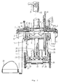
- a clutch bearing 2 is inserted in each crank 1 such that the bottom bracket bearing axle 3 can only be driven by the crank 1 to drive the chain wheel 4 to carry the free-wheel hub (not shown) to rotate in one direction via the bushed chain 5.
- the bottom bracket bearing axle 3 is transversely disposed to freely rotate in the bottom bracket bearing 7 which is fastened in the bottom bracket 6 of a bicycle.
- the chain wheel 4 is attached to a chain wheel holder 9 and mounted on the bottom bracket bearing axle 3 at one end and driven by the bushed chain 5 to cause the free wheel of said bicycle to rotate (same as in regular bicycles).
- a fixed lock wheel 10 is mounted on the bottom bracket bearing axle 3 at an opposite end.
- the chain wheel holder 9 and the fixed lock wheel 10 have each a plurality of stub rods 11 at an outer side and respectively firmly secured to the bottom bracket bearing axle 3 at the two opposite sides of the bottom bracket 6 by means of a square hole 12 which is made on the fixed lock wheel 10 at the centre and a lock nut 13.
- a clutch bearing 2 each is mounted between the bottom bracket bearing axle 3 and each crank 1 (either the one at the left side or the other at the right side), the bottom bracket bearing axle 3 are driven to rotate only when the two cranks 1 of the bicycle are simultaneously rotated in a specific direction.
- a bushing 16 is mounted on each crank 1 to secure a reciprocating wheel 15 each thereto permitting said reciprocating wheel 15 to freely rotate on the corresponding crank 1.
- the reciprocating wheel 15 Similar to the fixed lock wheel 10 and the chain wheel holder 9, the reciprocating wheel 15 also has a plurality of stub rods 11 on the face thereof.
- Each crank 1 has a plurality of semi-circular grooves 17A longitudinally made on the outer wall surface thereon at one end.
- a movable lock wheel 18 each is respectively mounted on each crank 1.
- the movable lock wheel 18 has a plurality of semi-circular grooves 17B on the inner wall of the wheel hub thereof respectively disposed to match with the semi-circular grooves 17A on each crank 1 for holding a pluralit
- the movable lock wheel 18 is prohibited from rotary motion but can only be moved to slide horizontally.
- the movable lock wheel 18 has a plurality of locking holes 32 respectively made at locations corresponding to the stub rods 11 of the reciprocating wheel 15, the chain wheel holder 9 and the fixed lock wheel 10.
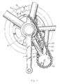
- an auxiliary bracket 22 made at the bottom of the bottom bracket 6 for holding an auxiliary axle 23 which has two auxiliary chain wheels 24 respectively mounted thereon at the two opposite ends thereof.
- Two chain lines 25 in well measured length are respectively connected between the two chain wheels 24 and the reciprocating wheels 15.
- the two chain lines 25 have each two opposite ends respectively fixedly connected to the auxiliary chain wheel and the reciprocating wheel at either side and, are respectively crossed over each other. Therefore, when the reciprocating wheel 15 at one side is driven by one auxiliary chain wheel and the connected chain line to rotate in clockwise direction, the reciprocating wheel 15 at the other side is driven by the other auxiliary chain wheel and chain line to rotate in counter-clockwise direction, and vice versa.
- control crank brackets 27 at the top of the auxiliary bracket 22 below the bottom bracket 6 for mounting two control cranks 26 at two opposite side by a pivot 28 each, which two control cranks 26 have each an upper end respectively attached to the movable lock wheels 18.
- Two double-helical springs 29 are respectively mounted on the two control cranks 26, having each two opposite ends respectively stopped against the control cranks 26 and the control crank brackets 27. Because of the double-helical springs 29, the upper end of the control cranks 26 are constantly respectively forced to incline inwards (toward each other). Therefore, the two control cranks 26 can be controlled to drive the movable lock wheels 18 to displace horizontally.
- the control cranks 26 have each a terminal end connected to a control lever 31 through a steel wire 30 respectively, which control lever 31 is mounted the handlebar of the bicycle at either end to control the position of the corresponding movable lock wheel 18. Only one control lever 30 and steel wire 31 are shown in the drawings.
- the top end of the corresponding control crank 26 can be pulled by the corresponding steel wire 30 to extend outwards.
- the corresponding double-helical spring 29 immediately forces the corresponding control crank 26 to incline inwards again. Therefore, through the aforesaid operation, the movable lock wheels 18 are displaced to the left or right as seen in Figure 2.
- the two control cranks 26 are respectively forced by the two helical springs 29 to incline inwards, causing the two movable lock wheels 18 to move toward the fixed lock wheel 10 and the chain wheel holder 9 respectively (the movable lock wheels are respectively disengaged from the reciprocating wheels) so that the locking holes 32 engage with the stub rods 11 of the fixed lock wheel 10 or the chain wheel holder 9.
- the two cranks 1 are respectively coupled to the bottom bracket 6 in 180x angle relative to each other and driven by foot pedals to rotate in the same direction (in function as the two cranks of a conventional bicycle or stationary bicycle).
Landscapes
- Engineering & Computer Science (AREA)
- Chemical & Material Sciences (AREA)
- Combustion & Propulsion (AREA)
- Transportation (AREA)
- Mechanical Engineering (AREA)
- Transmission Devices (AREA)
Claims (1)
- Kraftübertragungsmechanismus für Fahrräder der Art mit einer unteren halterungstragenden Achse (3), die in einer unteren Halterung (6) befestigt ist und von zwei Kurbeln (1) angetrieben wird, um ein Kettenrad (4) anzutreiben, um ein Freilaufrad zur Rotation über eine Hülsenkette (5) zu veranlassen, wobei der Mechanismus folgendes umfaßt:
einen Kettenradhalter (9), der in das genannte Ketten-rad (4) eingebaut und an einem Ende der genannten unteren halterungstragenden Achse (3) montiert ist;
ein feststehendes Sperrad (10), das am gegenüberlie-genden Ende der genannten unteren halterungstragenden Achse (3) an dem genannten Kettenradhalter (9) montiert ist;
Kupplungslager (2), von denen an beiden Enden der genannten unteren halterungstragenden Achse (3) jeweils eines montiert ist und jeweils eine der genannten beiden Kurbeln (1) trägt;
jeweils ein auf den genannten Kurbein (1) montiertes hin- und herbewegliches Rad (15) und ein bewegliches Sperr-rad (18), wobei die genannten hin- und herbeweglichen Räder (15) auf den genannten Kurbeln (1) frei beweglich sind;
Stahlkugeln (19), die sich zwischen den genannten be-weglichen Sperrädern (18) und den genannten Kurbeln (1) be-finden, um eine Rotation der genannten beweglichen Sperr-räder (18) auf den genannten Kurbeln (1) zu verhindern und um eine Bewegung der genannten beweglichen Sperräder (18) auf den genannten Kurbeln axial zu der genannten unteren halterungstragenden Achse (3) zuzulassen, um eine Verkupp-lung der genannten beweglichen Sperräder (18) mit den ge-nannten hin- und herbeweglichen Rädern (15), dem genannten feststehenden Sperrad (10) oder dem genannten Kettenradhal-ter (9) zu ermöglichen;
einen hin- und herbeweglichen Hebelbewegungsmechanis-mus, umfassend eine Zusatzhalterung (22), die unten mit der genannten unteren Halterung (6) verbunden ist, eine Zusatz-achse (23), die drehbar in der genannten Zusatzhalterung (22) montiert ist, zwei Zusatzkettenräder (24), die jeweils an gegenüberliegenden Enden der genannten Zusatzachse (23) montiert sind, zwei Kettenstränge (25), die jeweils zwi-schen den genannten Zusatzkettenrädern (24) und den genann-ten hin- und herbeweglichen Rädern (15) montiert und von-einander beabstandet sind und einander überkreuzen. so daß die genannten hin- und herbeweglichen Räder (15) so ange-trieben werden können, daß sie sich in einander entgegen-gesetzten Richtungen drehen;
einen Steuermechanismus, umfassend zwei Steuerkurbel-halterungen (27) oberhalb der genannten Zusatzhalterung (22), zwei Steuerkurbelarme (26), bei denen jeweils ein Ende an den genannten Steuerkurbelhalterungen und das ge-genüberliegende Ende an den genannten beweglichen Sperr-rädern (18) befestigt ist, zwei Doppelspiralfedern (29), bei denen jeweils zwei gegenüberliegende Enden gegen die genannten Steuerkurbelarme (26) und die genannten Steuer-kurbelhalterungen (27) stoßen, zwei Steuerhebel (31), die jeweils durch einen Stahldraht (30), der jeweils die ge-nannten beweglichen Sperräder (18) axial zu der genannten unteren halterungstragenden Achse (3) verschiebt, mit den genannten Steuerkurbelarmen verbunden sind;
und wobei die genannten Steuerhebel (31) jeweils so eingestellt werden können, daß sie die genannten bewegli-chen Sperräder (18) so bewegen, daß sie sich mit dem ge-nannten hin- und herbeweglichen Rad (15) oder mit dem ge-nannten feststehenden Sperrad (10) an einem Ende der unte-ren halterungstragenden Achse (3) und mit dem anderen ge-nannten hin- und herbeweglichen Rad (15) oder dem genannten Kettenradhalter (9) am anderen Ende der genannten unteren haltetungstragenden Achse (3) verkuppeln, so daß die ge-nannten beiden Kurbein (1) so angetrieben werden können, daß sie abwechselnd oder synchron eine hin- und hergehende Hebelbewegung oder eine runde Kurbeibewegung ausführen.
Applications Claiming Priority (2)
| Application Number | Priority Date | Filing Date | Title |
|---|---|---|---|
| US07/675,812 US5088340A (en) | 1991-03-27 | 1991-03-27 | Multipurpose transmission mechanism for bicycles |
| US675812 | 1991-03-27 |
Publications (2)
| Publication Number | Publication Date |
|---|---|
| EP0505643A1 EP0505643A1 (de) | 1992-09-30 |
| EP0505643B1 true EP0505643B1 (de) | 1996-04-10 |
Family
ID=24712071
Family Applications (1)
| Application Number | Title | Priority Date | Filing Date |
|---|---|---|---|
| EP91310086A Expired - Lifetime EP0505643B1 (de) | 1991-03-27 | 1991-10-31 | Mehrzweckübersetzungsgetriebe für ein Fahrrad |
Country Status (7)
| Country | Link |
|---|---|
| US (1) | US5088340A (de) |
| EP (1) | EP0505643B1 (de) |
| KR (1) | KR940005540Y1 (de) |
| CN (1) | CN2103504U (de) |
| AU (1) | AU632979B2 (de) |
| CA (1) | CA2052997A1 (de) |
| DE (1) | DE69118678D1 (de) |
Cited By (1)
| Publication number | Priority date | Publication date | Assignee | Title |
|---|---|---|---|---|
| EP4534154A1 (de) * | 2023-10-02 | 2025-04-09 | Sportstech Brands Holding GmbH | Fahrrad-heimtrainer mit anpassbarem kurbelsystem |
Families Citing this family (23)
| Publication number | Priority date | Publication date | Assignee | Title |
|---|---|---|---|---|
| US5351575A (en) * | 1993-02-24 | 1994-10-04 | Nathan Overby | Pumping propulsion system |
| US5765847A (en) * | 1994-02-04 | 1998-06-16 | Novator, L.L.C. | Pedal mechanism for cycle and exercise equipment |
| US5860329A (en) * | 1997-03-17 | 1999-01-19 | Day; Franklin J. | Pedaling mechanism for bicycles and the like |
| USD401538S (en) | 1997-03-25 | 1998-11-24 | Chen-Ching Chang | Chainless transmission unit of a bicycle |
| FR2777529A1 (fr) * | 1998-04-21 | 1999-10-22 | Chanradi Chhim | Dispositif de propulsion de la bicyclette par pedalage a mode variable |
| FR2792904A1 (fr) * | 1999-04-28 | 2000-11-03 | Mohamed El Yazid Seraoui | Systeme de pedales a cliquets pour bicyclette |
| US20050116438A1 (en) * | 2003-12-01 | 2005-06-02 | Wang Chien K. | Bicycle with two pedaling modes |
| US7727125B2 (en) * | 2004-11-01 | 2010-06-01 | Day Franklin J | Exercise machine and method for use in training selected muscle groups |
| US7530932B2 (en) * | 2004-11-29 | 2009-05-12 | A.A.R.M.-1 Llc | Upper-body exercise cycle |
| CN2871369Y (zh) | 2005-02-02 | 2007-02-21 | 郑玉女 | 多功能自行车传动机构改良 |
| US7544139B2 (en) * | 2005-02-02 | 2009-06-09 | Ok Yeo Chong | Multifunctional pedaling motion bicycle |
| US20100064845A1 (en) * | 2005-07-19 | 2010-03-18 | Bear Corporation | Bicycle Crank Assembly |
| US7267030B2 (en) * | 2005-07-19 | 2007-09-11 | Bear Corporation | Bicycle crank assembly |
| US7980156B2 (en) * | 2007-02-12 | 2011-07-19 | Ok Yeo Chong | Multipurpose transmission mechanism for bicycle with quick assembly device |
| ES2347285T3 (es) | 2007-03-23 | 2010-10-27 | Chong, Ok Yeo | Mecanismo de transmision multifuncion para bicicleta. |
| US7758475B2 (en) * | 2007-03-26 | 2010-07-20 | Five Girl, Inc. | Upper body exercise cycle |
| US20100167881A1 (en) * | 2008-12-31 | 2010-07-01 | Day Franklin J | Crank mechanism and bicycle incorporating same |
| WO2013172735A1 (ru) * | 2012-05-14 | 2013-11-21 | Общество с ограниченной ответственностью "МЭРС" | Привод педальных транспортных средств |
| RU2525185C2 (ru) * | 2012-05-14 | 2014-08-10 | Общество с ограниченной ответственностью "МЭРС" | Привод педальных транспортных средств |
| KR101260009B1 (ko) * | 2012-07-10 | 2013-05-06 | 최영오 | 자전거 |
| CN105261287B (zh) * | 2015-11-05 | 2017-08-25 | 浙江工业职业技术学院 | 一种机械仿生马演示模型 |
| US10322767B2 (en) | 2016-01-24 | 2019-06-18 | Costel Dragomir | Carry-on foldable stepper scooter |
| TWM537062U (zh) * | 2016-08-09 | 2017-02-21 | Vivasports Co Ltd | 健身或腳踏車用之傳動裝置 |
Family Cites Families (10)
| Publication number | Priority date | Publication date | Assignee | Title |
|---|---|---|---|---|
| US608008A (en) * | 1898-07-26 | Lieb schneidewind | ||
| US600450A (en) * | 1898-03-08 | richmond | ||
| CA465448A (en) * | 1950-05-30 | Elie Bascle Charles | Driving mechanism for bicycles and similar applications | |
| FR409587A (fr) * | 1908-11-28 | 1910-04-26 | John Hill | Mécanisme de commande pour bicyclettes et leur équivalent |
| AT152590B (de) * | 1936-04-17 | 1938-02-25 | Karl Grieszmayer | Fahrradgetriebe. |
| US2391809A (en) * | 1942-10-20 | 1945-12-25 | Wasem Jacques | Pedal drive |
| US4029334A (en) * | 1973-11-19 | 1977-06-14 | Cycle-Drive Corporation | Bicycle drive assembly |
| US4019230A (en) * | 1975-06-30 | 1977-04-26 | Pollard Melville R | Reciprocating powered bicycle |
| US4300784A (en) * | 1978-02-21 | 1981-11-17 | Energenic Propulsions, Ltd. | Efficient, versatile oscillating pedal cycle |
| US4564206A (en) * | 1983-10-11 | 1986-01-14 | Lenhardt Larry G | Pedal drive |
-
1991
- 1991-03-27 US US07/675,812 patent/US5088340A/en not_active Expired - Fee Related
- 1991-10-08 AU AU85620/91A patent/AU632979B2/en not_active Ceased
- 1991-10-08 CA CA002052997A patent/CA2052997A1/en not_active Abandoned
- 1991-10-15 CN CN91226879U patent/CN2103504U/zh active Granted
- 1991-10-31 DE DE69118678T patent/DE69118678D1/de not_active Expired - Lifetime
- 1991-10-31 EP EP91310086A patent/EP0505643B1/de not_active Expired - Lifetime
-
1992
- 1992-03-20 KR KR92004507U patent/KR940005540Y1/ko not_active Expired - Lifetime
Cited By (1)
| Publication number | Priority date | Publication date | Assignee | Title |
|---|---|---|---|---|
| EP4534154A1 (de) * | 2023-10-02 | 2025-04-09 | Sportstech Brands Holding GmbH | Fahrrad-heimtrainer mit anpassbarem kurbelsystem |
Also Published As
| Publication number | Publication date |
|---|---|
| CN2103504U (zh) | 1992-05-06 |
| AU8562091A (en) | 1992-10-01 |
| EP0505643A1 (de) | 1992-09-30 |
| DE69118678D1 (de) | 1996-05-15 |
| CA2052997A1 (en) | 1992-09-28 |
| AU632979B2 (en) | 1993-01-14 |
| KR940005540Y1 (ko) | 1994-08-18 |
| KR920018047U (ko) | 1992-10-17 |
| US5088340A (en) | 1992-02-18 |
Similar Documents
| Publication | Publication Date | Title |
|---|---|---|
| EP0505643B1 (de) | Mehrzweckübersetzungsgetriebe für ein Fahrrad | |
| US6723029B2 (en) | Pedal mechanism for cycles | |
| US6840136B1 (en) | Pedal drive mechanism | |
| US4147370A (en) | Front wheel drive for a bicycle | |
| US5833257A (en) | Alternating drive for wheeled vehicles | |
| JPH0246436B2 (de) | ||
| US5290054A (en) | Linear drive recumbent cycle | |
| US5496051A (en) | Apparatus for propelling a manually-powered cycle | |
| WO1998051561A1 (en) | Reversible drive device for bicycles | |
| JPH0924887A (ja) | 自転車用前進駆動機構 | |
| CN1013695B (zh) | 一种单向离合器 | |
| KR20010031165A (ko) | 선형 구동 장치 | |
| RU2137656C1 (ru) | Велосипед | |
| CA2185657A1 (en) | Alternating drive for wheeled vehicles | |
| US20040150185A1 (en) | Front wheel drive handlebar for use with bicycles | |
| US3913947A (en) | Vehicle with variable speed transmission | |
| CN2167024Y (zh) | 往复式脚踏省力自行车 | |
| SU1507639A1 (ru) | Мускульный привод транспортного средства с возвратно-поступательным движением педалей | |
| USRE30078E (en) | Vehicle with variable speed transmission | |
| CN2223249Y (zh) | 自行车前轮驱动装置 | |
| CN214138837U (zh) | 一种活飞前置自行车 | |
| US20040262878A1 (en) | Lever enhanced pedaling system | |
| CN85203695U (zh) | 杆驱动式自行车的驱动机构 | |
| CN1005554B (zh) | 杠杆钢索传动能稳定停车的自行车 | |
| CN2277365Y (zh) | 自行车省力增速器 |
Legal Events
| Date | Code | Title | Description |
|---|---|---|---|
| PUAI | Public reference made under article 153(3) epc to a published international application that has entered the european phase |
Free format text: ORIGINAL CODE: 0009012 |
|
| AK | Designated contracting states |
Kind code of ref document: A1 Designated state(s): DE ES FR GB IT |
|
| 17P | Request for examination filed |
Effective date: 19921201 |
|
| 17Q | First examination report despatched |
Effective date: 19940203 |
|
| GRAA | (expected) grant |
Free format text: ORIGINAL CODE: 0009210 |
|
| RAP1 | Party data changed (applicant data changed or rights of an application transferred) |
Owner name: ABL PROPERTIES COMPANY |
|
| AK | Designated contracting states |
Kind code of ref document: B1 Designated state(s): DE ES FR GB IT |
|
| PG25 | Lapsed in a contracting state [announced via postgrant information from national office to epo] |
Ref country code: IT Free format text: LAPSE BECAUSE OF FAILURE TO SUBMIT A TRANSLATION OF THE DESCRIPTION OR TO PAY THE FEE WITHIN THE PRE;WARNING: LAPSES OF ITALIAN PATENTS WITH EFFECTIVE DATE BEFORE 2007 MAY HAVE OCCURRED AT ANY TIME BEFORE 2007. THE CORRECT EFFECTIVE DATE MAY BE DIFFERENT FROM THE ONE RECORDED.SCRIBED TIME-LIMIT Effective date: 19960410 Ref country code: FR Effective date: 19960410 Ref country code: ES Free format text: THE PATENT HAS BEEN ANNULLED BY A DECISION OF A NATIONAL AUTHORITY Effective date: 19960410 |
|
| REF | Corresponds to: |
Ref document number: 69118678 Country of ref document: DE Date of ref document: 19960515 |
|
| PG25 | Lapsed in a contracting state [announced via postgrant information from national office to epo] |
Ref country code: DE Effective date: 19960711 |
|
| EN | Fr: translation not filed | ||
| PG25 | Lapsed in a contracting state [announced via postgrant information from national office to epo] |
Ref country code: GB Effective date: 19961031 |
|
| PLBE | No opposition filed within time limit |
Free format text: ORIGINAL CODE: 0009261 |
|
| STAA | Information on the status of an ep patent application or granted ep patent |
Free format text: STATUS: NO OPPOSITION FILED WITHIN TIME LIMIT |
|
| 26N | No opposition filed | ||
| GBPC | Gb: european patent ceased through non-payment of renewal fee |
Effective date: 19961031 |