EP0505145B1 - Système de détection de bord d'image - Google Patents
Système de détection de bord d'image Download PDFInfo
- Publication number
- EP0505145B1 EP0505145B1 EP92302285A EP92302285A EP0505145B1 EP 0505145 B1 EP0505145 B1 EP 0505145B1 EP 92302285 A EP92302285 A EP 92302285A EP 92302285 A EP92302285 A EP 92302285A EP 0505145 B1 EP0505145 B1 EP 0505145B1
- Authority
- EP
- European Patent Office
- Prior art keywords
- edge
- image
- components
- error
- detecting
- Prior art date
- Legal status (The legal status is an assumption and is not a legal conclusion. Google has not performed a legal analysis and makes no representation as to the accuracy of the status listed.)
- Expired - Lifetime
Links
Images


Classifications
-
- G—PHYSICS
- G06—COMPUTING OR CALCULATING; COUNTING
- G06T—IMAGE DATA PROCESSING OR GENERATION, IN GENERAL
- G06T7/00—Image analysis
- G06T7/10—Segmentation; Edge detection
- G06T7/13—Edge detection
-
- G—PHYSICS
- G06—COMPUTING OR CALCULATING; COUNTING
- G06T—IMAGE DATA PROCESSING OR GENERATION, IN GENERAL
- G06T7/00—Image analysis
- G06T7/10—Segmentation; Edge detection
- G06T7/12—Edge-based segmentation
-
- G—PHYSICS
- G06—COMPUTING OR CALCULATING; COUNTING
- G06T—IMAGE DATA PROCESSING OR GENERATION, IN GENERAL
- G06T2207/00—Indexing scheme for image analysis or image enhancement
- G06T2207/10—Image acquisition modality
- G06T2207/10024—Color image
Definitions
- the present invention relates to an image-processing system for separating an image into lamellar components and vortex components and processing these components, and particularly, to a system for correctly detecting edges of an original color image, to reproduce the original color image.
- edges of an original color image are detected. Once the edges are detected, only the data of the detected edges are transmitted to the receiver, and at the receiving side, the original color image is reproduced by using the received data of edges and by using interpolation.
- JP-A-62 133 690 entitled as a color image transmission processing system
- JP-A-63 039 284 entitled as a color image edge-detecting and transmission processing system
- JP-A-2 066 149 entitled as a scalar data processing system.
- an original color image is separated into luminance components and chrominance components, and the chrominance components are separated into lamellar components that are scalar potential components and vortex components that are vector potential components.
- the vortex components are compressed as compact as possible for transmission, to reduce the quantity of data to transmit.
- the second Japanese patent application JP-A-62 133 690 detects an edge mainly using the luminance components
- the second Japanese patent application No. JP-A-63 039 284 more effectively detects edges by additionally using lamellar and vortex components.
- the first and the second Japanese patent applications are the original applications of priority for United States Patent No. US-A-4,908,698 issued on March 13, 1990 and European Patent application EP-A-0 293 225.
- JP-A-2 066 149 is the original application of priority for United State Patent Application Serial No. 666,712 (US-A-5 148 501 issued on September 15, 1992), which discloses data compression and reproduction of two-dimensional scalar data.
- the lamellar component is the first item, i.e., grad L, in the above expression
- the vortex component is the second item, i.e., rot (R ⁇ K), in the above expression.
- the vortex component rot V is zero.
- An object of the present invention is to provide a system for precisely and correctly detecting an edge of an image.
- a system for correctly detecting an edge of an image in which a first edge is corrected by a second edge which is an edge of an error between an original image and a reproduced image obtained by using the first edge is provided.
- a system for detecting an edge of an image comprising: a first edge detecting unit for extracting a first edge of an original image by using a first threshold; a reproduction processing unit, operatively connected to the first edge detecting unit, for reproducing the original image to obtain a reproduced image corresponding to the original image by using the first edge; an error extracting unit, operatively connected to the reproduction processing unit, for extracting an error between the original image and the reproduced image; a second edge detecting unit, operatively connected to the error extracting unit, for detecting a second edge of the error extracted by the error extracting unit by using a second threshold smaller than the first threshold; and an edge correcting unit, operatively connected to the first edge detecting unit and the second edge detecting unit, for correcting the first edge by logically adding the first edge and the second edge to obtain a corrected reproduced image.
- the system further comprises an image separating unit for separating the original image into image luminance components and image chrominance components, and error separating unit for separating the error into error luminance components and error chrominance components, the first edge being the edge of at least one of the image luminance components and the image chrominance components, and the second edge being the edge of at least one of the error luminance components and the error chrominance components.
- the first edge comprises image luminance divergence components that exceed the first threshold of the image luminance components
- the second edge comprises error luminance divergence components that exceed the second threshold of the error luminance components
- the first edge comprises image chrominance divergence components that exceed the first threshold of the image chrominance components
- the second edge comprises error chrominance divergence components that exceed the second threshold of the error chrominance components.
- the system further comprises an image chrominance separating unit for separating the image chrominance components into image lamellar components and image vortex components, and an error chrominance separating unit for separating the error chrominance components into error lamellar components and error vortex components, the first edge being the edge of at least one of the image lamellar components and the image vortex components, and the second edge being the edge of at least one of the error luminance components and the error chrominance components.
- the first edge comprises image lamellar divergence components that exceed the first threshold of the image lamellar components
- the second edge comprises error lamellar divergence components that exceed the second threshold of the error lamellar components.
- the first edge comprises image vortex divergence components that exceed the first threshold of the image vortex components
- the second edge comprises error vortex divergence components that exceed the second threshold, of the error vortex components
- the error extracting unit comprises a bulk error detecting unit for extracting a bulk error from the error; the bulk error expanding to a certain area.
- the bulk error detecting unit comprises an absolute value obtaining unit for obtaining the absolute value of a difference between the reproduced image output from the reproduction processing unit and the original image; an integration unit for calculating an integration of the output of the absolute value obtaining unit over a certain area, and a comparing unit for comparing the output of the integration unit with a predetermined threshold.
- the system further comprises a third edge detecting unit, operatively connected to receive the original image and to the edge correcting unit, for detecting a third edge of the original image by using a third threshold smaller than the first threshold, and a comparing unit, operatively connected to the second edge detecting unit and to the third edge detecting unit, for obtaining a difference between the second edge and the third edge, the first edge being corrected by adding the difference to the first edge.
- a third edge detecting unit operatively connected to receive the original image and to the edge correcting unit, for detecting a third edge of the original image by using a third threshold smaller than the first threshold
- a comparing unit operatively connected to the second edge detecting unit and to the third edge detecting unit, for obtaining a difference between the second edge and the third edge, the first edge being corrected by adding the difference to the first edge.
- the system further comprises an image reproducing unit, operatively connected to the edge correcting unit, for reproducing the original image to obtain a corrected reproduced image by using the corrected edge obtained by the edge correcting unit.
- a color image is transmitted and reproduced by transmitting luminance and chrominance components of pixels of the color image.
- Y, I, and Q are transmitted.
- the I and Q are transmitted on a subcarrier.
- Color signals (chrominance component signals) contain a considerable quantity of energy components. Therefore, if it is possible to reduce a part of the energy of color signals, it will be advantageous for compressing a transmission band and for chromaticity data processing.
- a conventional transmission processing system as shown in Fig. 1 has been proposed in view of the fact that the above-mentioned chrominance components can be represented with vector signals such as I and Q.
- numeral 1 represents a circle plate with a certain color forming a given color image
- 2 represents a background of the color image with a different color from the color image
- 3 represents vector lines representing a chrominance component of the color image.
- a horizontal straight section of the vector line 3 indicates a background color provided for the background 2.
- a straight oblique section of the vector line 3 indicates that the circle 1 has a different color from the background color.
- Numeral 4 is a separating and processing unit for separating the color image into luminance and chrominance components, and the chrominance component is separated into lamellar and vortex components as explained later in more detail.
- Numeral 5 is a transmission unit for encoding the lamellar and vortex components.
- the vortex components may not be encoded, or the number of bits thereof may be reduced for encoding because the percentage of the energy of the vortex component in the color image is very small.
- numeral 6 is a segment representing a lamellar component
- 7 is a segment representing a vortex component.
- Numeral 8 is a receiving unit that synthesizes the original color image by using the luminance component and the chrominance component.
- a color image is separated into luminance and chrominance components.
- the known chrominance component is given as a vector signal such as I and Q.
- a vector V is expressed as follows:
- a chrominance component can be expressed as a vector V, which may also be expressed as follows.
- V grad ⁇ + rot (A ⁇ K)
- the value ⁇ is a potential representing a lamellar component of the vector V.
- the lamellar component ⁇ can be represented by the lines 6 corresponding to the circle plate 1 and the background 2 having different colors, as shown in Fig. 1.
- the value A is a potential representing a vortex component of the vector V.
- the vortex component A can be represented by the lines 7 corresponding to the circle plate 1 and the background 2, as shown in Fig. 1.
- the receiving unit 8 can reproduce the original color image.
- the receiving unit 8 in Fig. 1 reproduces the original color image by using the transmitted luminance components and chrominance codes.
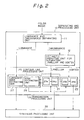
- Figure 2 shows a more practical example of a conventional color image transmitting system that can be applied to an embodiment of the present invention by modifying a part of the system.
- reference numeral 10 is a separating and processing unit that is the same as the separating and processing unit 4 in Fig. 1
- 20 is a transmission processing unit that is present in the transmission unit 5 in Fig. 1
- 30 is a synthesis processing unit that is present in the receiving unit 8 in Fig. 1.
- Reference numeral 11 is a luminance and chrominance separating unit that separates a given color image into luminance and chrominance components.
- a chrominance component is expressed as follows:
- ⁇ ' ⁇ / [a + (1-a)Y]
- ⁇ ' ⁇ / [a + (1-a)Y]
- a is a bias given as 0 ⁇ a ⁇ 1 to equalize the chrominance component vectors from 0 to 2 ⁇
- Numeral 12 is an arithmetic operating unit for separating the chrominance components into the lamellar components and and vortex components.
- the transmission processing unit 20 includes a lamellar transmission processing unit 21, a vortex transmission processing unit 22, and a contour processing unit 25.
- the lamellar transmission processing unit 21 includes a lamellar vector analyzing and connecting unit 23a for providing a divergence component of the lamellar component separated by the arithmetic operating unit 12 and preparing an edge by taking values greater than a certain threshold value, and a lamellar encoding unit 24a for band-compressing and encoding the divergence component provided by the lamellar vector analyzing and connecting unit 23a and the lamellar component separated by the arithmetic operating unit 12.
- the vortex transmission processing unit 22 comprises a vortex vector analyzing and connecting unit 23b for providing a rotation component of the vortex component separated by the arithmetic operating unit 12 and preparing an edge by taking values greater than a certain threshold value, and a vortex encoding unit 24b for band-compressing and encoding the rotation component output from the vortex vector analyzing and connecting unit 23b and the vortex component separated by the arithmetic operating unit 12.
- the contour processing unit 25 comprises an edge extracting unit 26 for comparing either one or both of the outputs of the lamellar vector analyzing and connecting unit 23a and vortex vector analyzing and connecting unit 23b with a predetermined reference value, thereby detecting edges of a color image, and an luminance edge extracting unit 27 for extracting edges of the color image according to the luminance component separated by the luminance and chrominance separation unit 11.
- the synthesis processing unit 30 receives the encoded data from the lamellar encoding unit 24a and vortex encoding unit 24b and the contour data from the contour processing unit 25, and synthesizes a color image.
- the divergence component output from the lamellar vector analyzing and connecting unit 23a for obtaining the divergence component of the lamellar component, and the rotation component output from the vortex vector analyzing and connecting unit 23b for obtaining the rotation component of the vortex component will not be zero but will be very large values; the edges being formed because of chrominance differences. On the other hand, on parts other than the edges, these values will be zero because the chrominance is uniform in these areas.
- the edge extracting unit 26 detects edges of a color image by comparing a divergence component output from the lamellar vector analyzing and connecting unit 23a and a rotation component output from the vortex vector analyzing and connecting unit 23b with a predetermined reference value. Therefore, edges due to chrominance differences are detectable even if there is no luminance difference.
- Lamellar and vortex components on a specific axis, divergence components of the lamellar components provided by the lamellar vector analyzing and connecting unit 23a, and rotation components of the vortex components provided by the vortex vector analyzing and connecting unit 23b are encoded and transmitted to the synthesis processing unit 30, which then combines chrominance components on all axes together.
- the divergence and rotation components are considered to be zero anywhere except the edges, so that these components can be omitted from the transmission signal in a similar way as in a monochrome image band compression for compressing the luminance components.
- the color image is transmitted with a very small quantity of encoded data.
- areas A and B have different chrominance vectors.
- the areas A and B are continuous with an area C having a width 2a interposing between them.
- a chrominance vector for the area A is V A
- a chrominance vector for the area B is V B .
- the vectors V A and V B can be expressed as: where ⁇ a is the absolute value of the vector V A ⁇ ⁇ b is the absolute value of the vector V B , ⁇ is the angle of the vector V A with respect to the x axis, and ⁇ is the angle of the vector V B with respect to the x axis.
- the absolute values of div V and rot V are not zero but are large values around the edge C of the color image and nearly zero anywhere except the edges.
- edges are detected by detecting positions where one or both of the absolute values of div V and rot V are larger than a predetermined value.
- FIG. 4 is a block diagram showing an edge detecting system according to an embodiment of the present invention.
- numeral 101 denotes an original color image
- 102 is a first edge detecting unit.
- the first edge detecting unit 102 employs a known means such as the separating and processing unit 10 and transmission processing unit 20 in Fig. 2, to detect edges or contours of the original color image 101 by using a predetermined threshold t.
- Numeral 103 is a reproduction processing unit that employs a known means such as the synthesis processing unit 30 in Fig. 2, to reproduce the original color image.
- the units 102 are used to reproduce the original color image. Since the threshold t in the first edge detecting unit 102 is too large for a gradually changing edge, a correct edge cannot be detected.
- a bulk error extracting unit 104 compares the original color image 101 and the image reproduced by the reproduction processing unit 103 to find errors between them.
- the bulk error extracting unit 104 extracts a bulk error that is not a mere noise error but an error expanding on a certain area of the image.
- the second edge detecting unit 105 employs an edge detection means that is similar to that employed by, for example, the first edge detecting unit 102, and finds edges from an error image based on the bulk error extracted by the bulk error extracting unit 104.
- a threshold for the second edge detecting unit 105 is selected to be sufficiently small so as to be able to detect more edges than the edges detected by the first edge detecting unit 102 at positions where the edges are expected to exist.
- the threshold for the second edge detecting unit 105 is t/C 1 , where C 1 is a constant larger than 1.
- a third edge detecting unit 106 may be disposed.
- the third edge detecting unit 106 detects edges from the original color image 101 in a similar manner to that of, for example, the first edge detecting unit 102.
- a threshold for the third detecting unit 106 is t/C 2 , where C 2 is a constant larger than 1, so that the unit 106 may detect more edge-like objects than the first edge detecting unit 102.
- Numeral 107 is an edge correcting unit.
- the edge correcting unit 107 logically adds the outputs from the first edge detecting unit 102 and from the second edge detecting unit 105 to obtain a correct edge.
- the edge correcting unit 107 first compares the output of the second edge detecting unit 105 and the output of the third edge detecting unit 106 to detect a new edge that was detected both by the second and third edge detecting units, and then adds the above-mentioned new edge with the output of the first edge detecting unit 102.
- an add logic is effected on the edges extracted from the bulk error image by the second edge detecting unit 105 and the many edges extracted by the third edge detecting unit 106 to find edge locations that have been missed by the first edge detecting unit 102, and then the edges that have been missed and found are added to the edges detected by the first edge detecting unit 102 to thereby provide correct edges.
- Numeral 108 is an image reproduction processing unit that reproduces a color image using a similar means to the reproduction processing unit 103 in Fig. 2.
- the only difference between the conventional reproduction processing unit 108 and the conventional reproduction processing unit 103 is that the unit 108 of the present invention uses the corrected edges obtained as described above, whereas, the conventional reproduction processing unit 103 directly uses the edges detected by the first edge detecting unit 102.
- edge correction unit 107 and the image reproduction processing unit 108 are connected by a transmission line 109.
- the edge detecting system processes the original color image 101, provides a reproduced color image; obtains an error image between the original image and the error image; detects edges on the error image; and corrects edges by adding edges that have been missed from the reproduced image.
- Figs. 5A to 5E are views explaining the edge detection carried out on the error image.
- Figs. 5A to 5E explain the edge detection by detecting a change of luminance components, it should be noted that the edge detection may also be carried out by detecting a change of chrominance components.
- Fig. 5A shows a position of a change of, for example, luminance on the original image. If the change shown in Fig. 5A is too small in comparison with the threshold value t of the first edge detecting unit 102, the edge corresponding to the change cannot be detected.
- Fig. 5B shows an original edge to be detected.
- Fig. 5C is a reproduced image provided by the reproduction processing unit 103 when the edge cannot be detected because the change in luminance shown in Fig.
- Fig. 5A shows too small in comparison with the threshold value t.
- Fig. 5D shows an error image obtained by the second error detecting unit 105.
- Fig. 5E shows the corrected edge obtained at the output of the edge correcting unit 107 by using the error image shown in Fig. 5D.
- the edge is extracted by using the error image, and the desired edge can be obtained by using the outputs of the first and the second edge detecting units 103 and 105.
- FIG. 6 is a block diagram showing the edge detecting system according to the second embodiment of the invention in more detail.
- the reference numerals correspond to those in the system shown in Fig. 4, and therefore, explanations of the same are omitted.
- the bulk error extracting unit 104 and the edge correcting unit 107 will be described in detail.
- the bulk error extracting unit 104 includes a comparing unit 31, a bulk error detecting unit 32, and an error image storing unit 33.
- the comparing unit 31 compares a reproduced image provided by the reproduction processing unit 103 with the original color image 101 to generate a difference between them.
- the bulk error detecting unit 32 extracts a bulk error from the difference output from the comparing unit 31.
- the bulk error and an error caused by a simple noise are separable from each other because the error caused by a simple noise is local. In this way, an error image is obtained.
- the edge correcting unit 107 includes an edge comparing unit 35 and an edge determining unit 36.
- the edge comparing unit 35 compares many edges that may include those that are not real edges detected by the third edge detecting unit 106 with edges output from the second edge detecting unit 105.
- the collated or coincident edges correspond to edges missed by the first edge detecting unit 102, and therefore, the missed edges are added to the output of the first edge detecting unit 102 by the edge determining unit 36 to determine correct edges.
- the image reproduction processing unit 108 reproduces the original image. It should be noted that, when the bulk error extracting unit 104 detects no bulk error, it is understood that the first edge detecting unit 102 has correctly detected the edges, and the image provided by the reproduction processing unit 103 is naturally adopted by an image adopting unit 34 in the same way as in the conventional system.
- the image reproduced by the image reproducing unit 108 or the image adopted by the image adopting unit 34 is stored in a reproduced image storing unit 109.
- the three edge detecting units 102, 105, and 106 may be realized by a single edge detecting unit having three different thresholds. Also, the reproduction processing unit 103 and the reproduction image processing unit 108 may be realized by a single processing unit.
- the edge detecting system shown in Fig. 6 is used according to an embodiment of the present invention.
- the original image 101 in Fig. 6 represents the luminance components separated from the luminance and chrominance separating unit 11 in Fig. 2.
- the edge detecting system shown in Fig. 6 is used for detecting edges with respect to the lamellar components.
- the original image 101 in Fig. 6 represents the divergence components of the lamellar components separated from the chrominance components by the arithmetic operating unit 12 in Fig. 2.
- the edge detecting system shown in Fig. 6 may also be used for detecting edges with respect to the vortex component.
- the original image 101 in Fig. 6 represents the rotation components of the vortex components separated from the chrominance components by the arithmetic operating unit 12 in Fig. 2.
- FIG. 7 is a block diagram showing the constitution of the bulk error detecting unit 104 in detail.
- the bulk error detecting unit 104 includes an absolute value generating circuit 321, an integration circuit 322, and a comparing circuit 323.
- the absolute circuit 321 generates an absolute value of an error signal component provided from the comparing unit 31.
- the integration circuit 322 integrates the absolute value over a predetermined area.
- the comparing circuit 323 compares the integrated value with a certain threshold TH. If the integrated value exceeds the threshold TH, the integrated value is given as an error image to the error image storing unit 33. If the integrated value is smaller than the threshold TH, the integrated value is not deemed as an error image so that the output of the reproduction processing unit 103 is adopted as a reproduced image.
- FIGS 8 through 11 are views explaining the effects of edge detection according to the embodiment of the present invention.
- Figure 8 shows a desired image that is the same as an original color image.
- chrominance components for example, change at edges.
- Figure 9 shows a reproduced image when a part of the original image is intentionally deleted. Because of the deletion of edges, the chrominance components in the reproduced image smoothly change at the positions where the edges have been deleted.
- Figure 10 shows a color image after correcting the edges according to the embodiment of the present invention.
- the deleted edges have been corrected.
- Black dots in Fig. 10 indicate the positions where edges have been supplemented. Based on the supplemented edges, an interpolation process is carried out for intermediate areas.
- Figs. 8 to 10 explain the edge detection with respect to the chrominance components of the original image, it is of course possible to correctly detect the edges of the luminance components. Further, with respect to the chrominance components, vortex components may be neglected so that only the correct edges with respect to the lamellar components may be detected.
- edges missed in the first edge detecting unit are accurately and correctly supplemented and a correct reproduced image can be obtained.
Landscapes
- Engineering & Computer Science (AREA)
- Computer Vision & Pattern Recognition (AREA)
- Physics & Mathematics (AREA)
- General Physics & Mathematics (AREA)
- Theoretical Computer Science (AREA)
- Color Television Systems (AREA)
- Compression Or Coding Systems Of Tv Signals (AREA)
- Image Analysis (AREA)
- Image Processing (AREA)
Claims (11)
- Système pour détecter un bord d'une image comprenant :un premier moyen de détection de bord (102) pour extraire un premier bord d'une image originale en utilisant un premier seuil ;un moyen de traitement de reproduction (103) connecté en fonctionnement audit premier moyen de détection de bord (102) pour reproduire l'image originale afin d'obtenir une image reproduite correspondant à ladite image originale en utilisant ledit premier bord ;un moyen d'extraction d'erreur (104) connecté en fonctionnement audit moyen de traitement de reproduction (103) pour extraire une erreur entre ladite image originale et ladite image reproduite ;un second moyen de détection de bord (105) connecté en fonctionnement audit moyen d'extraction d'erreur (104) pour détecter un second bord de ladite erreur extraite par ledit moyen d'extraction d'erreur (104) en utilisant un second seuil inférieur audit premier seuil ; etun moyen de correction de bord (107) connecté en fonctionnement audit premier moyen de détection de bord (102) et audit second moyen de détection de bord (105) pour corriger ledit premier bord en additionnant logiquement ledit premier bord et ledit second bord afin d'obtenir une image reproduite corrigée.
- Système pour détecter un bord d'une image selon la revendication 1, comprenant en outre un moyen de séparation d'image pour séparer ladite image originale selon des composantes de luminance d'image et des composantes de chrominance d'image et un moyen de séparation d'erreur pour séparer ladite erreur selon des composantes de luminance d'erreur et des composantes de chrominance d'erreur, ledit premier bord étant le bord d'au moins une composante prise parmi lesdites composantes de luminance d'image et lesdites composantes de chrominance d'image et ledit second bord étant le bord d'au moins une composante prise parmi lesdites composantes de luminance d'erreur et lesdites composantes de chrominance d'erreur.
- Système pour détecter un bord d'une image selon la revendication 2, dans lequel ledit premier bord comprend des composantes de divergence de luminance d'image qui excèdent ledit premier seuil desdites composantes de luminance d'image et ledit second bord comprend des composantes de divergence de luminance d'erreur qui excèdent ledit second seuil desdites composantes de luminance d'erreur.
- Système pour détecter un bord d'une image selon la revendication 2, dans lequel ledit premier bord comprend des composantes de divergence de chrominance d'image qui excèdent ledit premier seuil desdites composantes de chrominance d'image et ledit second bord comprend des composantes de divergence de chrominance d'erreur qui excèdent ledit second seuil desdites composantes de chrominance d'erreur.
- Système pour détecter un bord d'une image selon la revendication 2, comprenant en outre un moyen de séparation de chrominance d'image pour séparer lesdites composantes de chrominance d'image selon des composantes lamellaires d'image et selon des composantes de vortex d'image et un moyen de séparation de chrominance d'erreur pour séparer lesdites composantes de chrominance d'erreur selon des composantes lamellaires d'erreur et des composantes de vortex d'erreur, ledit premier bord étant le bord d'au moins une composante prise parmi lesdites composantes lamellaires d'image et lesdites composantes de vortex d'image et ledit second bord étant le bord d'au moins une composante prise parmi lesdites composantes de luminance d'erreur et lesdites composantes de chrominance d'erreur.
- Système pour détecter un bord d'une image selon la revendication 5, dans lequel ledit premier bord comprend des composantes de divergence lamellaires d'image qui excèdent ledit premier seuil desdites composantes lamellaires d'image et ledit second bord comprend des composantes de divergence lamellaires d'erreur qui excèdent ledit second seuil desdites composantes lamellaires d'erreur.
- Système pour détecter un bord d'une image selon la revendication 5, dans lequel ledit premier bord comprend des composantes de divergence de vortex d'image qui excèdent ledit premier seuil desdites composantes de vortex d'image et ledit second bord comprend des composantes de divergence de vortex d'erreur qui excèdent ledit second seuil desdites composantes de vortex d'erreur.
- Système pour détecter un bord d'une image selon la revendication 1, dans lequel ledit moyen d'extraction d'erreur (104) comprend un moyen de détection d'erreur globale (32) pour extraire une erreur globale à partir de ladite erreur, ladite erreur globale s'étendant sur une certaine zone.
- Système pour détecter un bord d'une image selon la revendication 8, dans lequel ledit moyen de détection d'erreur globale (32) comprend un moyen d'obtention de valeur absolue (321) pour obtenir la valeur absolue d'une différence entre ladite sortie d'image reproduite provenant dudit moyen de traitement de reproduction (103) et ladite image originale, un moyen d'intégration (322) pour calculer une intégration de la sortie dudit moyen d'obtention de valeur absolue sur une certaine zone et un moyen de comparaison (323) pour comparer la sortie dudit moyen d'intégration (322) à un seuil prédéterminé.
- Système pour détecter un bord d'une image selon l'une quelconque des revendications précédentes, comprenant en outre un troisième moyen de détection de bord (106) connecté en fonctionnement pour recevoir ladite image originale audit moyen de correction de bord (107) pour détecter un troisième bord de ladite image originale en utilisant un troisième seuil inférieur audit premier seuil et un moyen de comparaison (35) connecté en fonctionnement audit second moyen de détection de bord (105) et audit troisième moyen de détection de bord (106) pour obtenir une différence entre ledit second bord et ledit troisième bord, ledit premier bord étant corrigé en additionnant ladite différence audit premier bord.
- Système pour détecter un bord d'une image selon l'une quelconque des revendications précédentes, comprenant en outre un moyen de reproduction d'image (108) connecté en fonctionnement audit moyen de correction de bord (107) pour reproduire ladite image originale afin d'obtenir une image reproduite corrigée en utilisant le bord corrigé obtenu par ledit moyen de correction de bord (107).
Applications Claiming Priority (2)
| Application Number | Priority Date | Filing Date | Title |
|---|---|---|---|
| JP3051867A JP2585874B2 (ja) | 1991-03-18 | 1991-03-18 | カラー画像のエッジ検出方式 |
| JP51867/91 | 1991-03-18 |
Publications (3)
| Publication Number | Publication Date |
|---|---|
| EP0505145A2 EP0505145A2 (fr) | 1992-09-23 |
| EP0505145A3 EP0505145A3 (en) | 1993-10-13 |
| EP0505145B1 true EP0505145B1 (fr) | 1998-07-08 |
Family
ID=12898831
Family Applications (1)
| Application Number | Title | Priority Date | Filing Date |
|---|---|---|---|
| EP92302285A Expired - Lifetime EP0505145B1 (fr) | 1991-03-18 | 1992-03-17 | Système de détection de bord d'image |
Country Status (5)
| Country | Link |
|---|---|
| US (1) | US5444798A (fr) |
| EP (1) | EP0505145B1 (fr) |
| JP (1) | JP2585874B2 (fr) |
| CA (1) | CA2063158C (fr) |
| DE (1) | DE69226112T2 (fr) |
Families Citing this family (23)
| Publication number | Priority date | Publication date | Assignee | Title |
|---|---|---|---|---|
| JP2938739B2 (ja) * | 1993-02-26 | 1999-08-25 | 富士通株式会社 | 動画像処理装置 |
| US20030174864A1 (en) * | 1997-10-27 | 2003-09-18 | Digital Biometrics, Inc. | Gambling chip recognition system |
| EP0878970A3 (fr) * | 1997-05-16 | 1999-08-18 | Matsushita Electric Industrial Co., Ltd. | Système de mesure de l'erreur d'alignement et de l'aberration chromatique d'un capteur d'image pour une caméra vidéo |
| DE69943141D1 (de) | 1998-05-20 | 2011-03-03 | Canon Kk | Photovoltaische Leistungserzeugungsvorrichtung |
| JP3501031B2 (ja) * | 1999-08-24 | 2004-02-23 | 日本電気株式会社 | 画像領域判定装置、画像領域判定方法及びそのプログラムを記憶した記憶媒体 |
| US20010004838A1 (en) * | 1999-10-29 | 2001-06-28 | Wong Kenneth Kai | Integrated heat exchanger system for producing carbon dioxide |
| US6894699B2 (en) * | 2000-07-21 | 2005-05-17 | Mitsubishi Denki Kabushiki Kaisha | Image display device employing selective or asymmetrical smoothing |
| JP4329271B2 (ja) * | 2001-03-22 | 2009-09-09 | コニカミノルタビジネステクノロジーズ株式会社 | 画像処理装置、画像形成装置、および画像処理方法 |
| US6636045B2 (en) * | 2001-04-03 | 2003-10-21 | Baker Hughes Incorporated | Method of determining formation anisotropy in deviated wells using separation of induction mode |
| US7053953B2 (en) * | 2001-12-21 | 2006-05-30 | Eastman Kodak Company | Method and camera system for blurring portions of a verification image to show out of focus areas in a captured archival image |
| US7454123B2 (en) * | 2002-06-06 | 2008-11-18 | Intel Corporation | Personal video recorder having reduced overscan coding |
| US7057664B2 (en) * | 2002-10-18 | 2006-06-06 | Broadcom Corporation | Method and system for converting interlaced formatted video to progressive scan video using a color edge detection scheme |
| US6907194B2 (en) | 2002-11-12 | 2005-06-14 | Eastman Kodak Company | Camera having continuously cropping viewfinder |
| US7561793B2 (en) * | 2002-11-12 | 2009-07-14 | Eastman Kodak Company | User interface for controlling cropping in electronic camera |
| US7006764B2 (en) * | 2002-11-12 | 2006-02-28 | Eastman Kodak Company | User interface for controlling cropping in electronic camera |
| US7327890B2 (en) | 2002-12-20 | 2008-02-05 | Eastman Kodak Company | Imaging method and system for determining an area of importance in an archival image |
| US20050134719A1 (en) * | 2003-12-23 | 2005-06-23 | Eastman Kodak Company | Display device with automatic area of importance display |
| AU2005201322B2 (en) * | 2004-03-26 | 2009-11-05 | Sri Sports Limited | Golf swing-measuring system |
| US8659619B2 (en) | 2004-03-26 | 2014-02-25 | Intellectual Ventures Fund 83 Llc | Display device and method for determining an area of importance in an original image |
| JP4926116B2 (ja) * | 2008-04-16 | 2012-05-09 | 株式会社日立ハイテクノロジーズ | 画像検査装置 |
| US20090262136A1 (en) * | 2008-04-22 | 2009-10-22 | Tischer Steven N | Methods, Systems, and Products for Transforming and Rendering Media Data |
| US8971637B1 (en) | 2012-07-16 | 2015-03-03 | Matrox Electronic Systems Ltd. | Method and system for identifying an edge in an image |
| CN114648453A (zh) * | 2022-03-01 | 2022-06-21 | 厦门聚视智创科技有限公司 | 一种视觉检测中数字图片强干扰特征的消除方法 |
Family Cites Families (4)
| Publication number | Priority date | Publication date | Assignee | Title |
|---|---|---|---|---|
| JPS59133414A (ja) * | 1983-01-21 | 1984-07-31 | Agency Of Ind Science & Technol | 楕円形状検出方法とその装置 |
| DE3839299C2 (de) * | 1987-11-20 | 1995-06-01 | Canon Kk | Bildverarbeitungseinrichtung |
| JP2507578B2 (ja) * | 1989-02-09 | 1996-06-12 | 富士通株式会社 | カラ―描画ワ―クステ―ション |
| JP3072766B2 (ja) * | 1990-03-16 | 2000-08-07 | 富士通株式会社 | スカラー・データ処理方式 |
-
1991
- 1991-03-18 JP JP3051867A patent/JP2585874B2/ja not_active Expired - Fee Related
-
1992
- 1992-03-16 CA CA002063158A patent/CA2063158C/fr not_active Expired - Fee Related
- 1992-03-17 DE DE69226112T patent/DE69226112T2/de not_active Expired - Fee Related
- 1992-03-17 EP EP92302285A patent/EP0505145B1/fr not_active Expired - Lifetime
-
1993
- 1993-12-28 US US08/174,627 patent/US5444798A/en not_active Expired - Fee Related
Non-Patent Citations (1)
| Title |
|---|
| 57 - 83 STEFAN CARLSSON 'Sketch Based Coding of Grey Level Images.' * |
Also Published As
| Publication number | Publication date |
|---|---|
| EP0505145A2 (fr) | 1992-09-23 |
| CA2063158C (fr) | 1996-12-17 |
| CA2063158A1 (fr) | 1992-09-19 |
| US5444798A (en) | 1995-08-22 |
| JP2585874B2 (ja) | 1997-02-26 |
| EP0505145A3 (en) | 1993-10-13 |
| JPH04287180A (ja) | 1992-10-12 |
| DE69226112T2 (de) | 1998-10-22 |
| DE69226112D1 (de) | 1998-08-13 |
Similar Documents
| Publication | Publication Date | Title |
|---|---|---|
| EP0505145B1 (fr) | Système de détection de bord d'image | |
| EP0692917B1 (fr) | Procédé pour la conversion d'images bidimensionnelles dans des images tridimensionnelles | |
| US6882445B1 (en) | Color gamut compression apparatus and method | |
| EP0376330B1 (fr) | Circuit et méthode de détection de mouvement et de séparation Y/C pour la détection de mouvement dans une image d'affichage télévision | |
| CA2214828A1 (fr) | Procede et appareil pour la compression et la decompression d'images numeriques en couleur | |
| US5097330A (en) | High definition television transmission and reception system with reduced data throughput | |
| US7289665B2 (en) | Image processing device and image processing program | |
| US4982270A (en) | Video data transmitting system | |
| EP0460596B1 (fr) | Appareil pour corriger la teinte d'un signal vidéo | |
| EP0293225B1 (fr) | Système de traitement d'image couleur | |
| EP1689196B1 (fr) | Masquage d'erreurs pour des signaux vidéo | |
| EP1035731B1 (fr) | Procédé et système de traitement d'images | |
| US6483550B1 (en) | Video signal level converting device and video signal analog-to-digital converter | |
| EP0358625B1 (fr) | Procédé pour former un champ de vecteurs de mouvement pour la transmission d'informations se rapportant à des images mobiles | |
| US6519001B1 (en) | Color signal separating circuit pure color signals | |
| JP2907663B2 (ja) | 動きベクトル検出方法 | |
| JPH01318491A (ja) | 動き検出回路及びエッジ検出回路 | |
| JP2000138949A (ja) | 画像情報変換装置および変換方法 | |
| US7738708B2 (en) | System and method for aligning chroma pixels | |
| WO2000064189A9 (fr) | Limitation de couleur stabilisee sur un systeme d'edition numerique non lineaire | |
| JPH01277092A (ja) | 動き検出回路 | |
| US4933760A (en) | Movement detecting circuit | |
| JPH02271789A (ja) | 映像信号送受信システム、映像信号受信装置及び映像信号送受信方法 | |
| EP0561399B1 (fr) | Dispositif de détection de mouvement dans une image d'un signal de télévision à définition étendue, avec une précision améliorée | |
| US20100232695A1 (en) | Video signal processing apparatus and computer-readable recording medium having recorded therein video signal processing program |
Legal Events
| Date | Code | Title | Description |
|---|---|---|---|
| PUAI | Public reference made under article 153(3) epc to a published international application that has entered the european phase |
Free format text: ORIGINAL CODE: 0009012 |
|
| AK | Designated contracting states |
Kind code of ref document: A2 Designated state(s): DE FR GB |
|
| PUAL | Search report despatched |
Free format text: ORIGINAL CODE: 0009013 |
|
| AK | Designated contracting states |
Kind code of ref document: A3 Designated state(s): DE FR GB |
|
| 17P | Request for examination filed |
Effective date: 19940406 |
|
| GRAG | Despatch of communication of intention to grant |
Free format text: ORIGINAL CODE: EPIDOS AGRA |
|
| 17Q | First examination report despatched |
Effective date: 19970904 |
|
| GRAG | Despatch of communication of intention to grant |
Free format text: ORIGINAL CODE: EPIDOS AGRA |
|
| GRAH | Despatch of communication of intention to grant a patent |
Free format text: ORIGINAL CODE: EPIDOS IGRA |
|
| GRAH | Despatch of communication of intention to grant a patent |
Free format text: ORIGINAL CODE: EPIDOS IGRA |
|
| GRAA | (expected) grant |
Free format text: ORIGINAL CODE: 0009210 |
|
| AK | Designated contracting states |
Kind code of ref document: B1 Designated state(s): DE FR GB |
|
| REF | Corresponds to: |
Ref document number: 69226112 Country of ref document: DE Date of ref document: 19980813 |
|
| ET | Fr: translation filed | ||
| PLBE | No opposition filed within time limit |
Free format text: ORIGINAL CODE: 0009261 |
|
| STAA | Information on the status of an ep patent application or granted ep patent |
Free format text: STATUS: NO OPPOSITION FILED WITHIN TIME LIMIT |
|
| 26N | No opposition filed | ||
| REG | Reference to a national code |
Ref country code: GB Ref legal event code: IF02 |
|
| PGFP | Annual fee paid to national office [announced via postgrant information from national office to epo] |
Ref country code: FR Payment date: 20060308 Year of fee payment: 15 |
|
| PGFP | Annual fee paid to national office [announced via postgrant information from national office to epo] |
Ref country code: DE Payment date: 20060309 Year of fee payment: 15 |
|
| PGFP | Annual fee paid to national office [announced via postgrant information from national office to epo] |
Ref country code: GB Payment date: 20060315 Year of fee payment: 15 |
|
| GBPC | Gb: european patent ceased through non-payment of renewal fee |
Effective date: 20070317 |
|
| REG | Reference to a national code |
Ref country code: FR Ref legal event code: ST Effective date: 20071130 |
|
| PG25 | Lapsed in a contracting state [announced via postgrant information from national office to epo] |
Ref country code: DE Free format text: LAPSE BECAUSE OF NON-PAYMENT OF DUE FEES Effective date: 20071002 |
|
| PG25 | Lapsed in a contracting state [announced via postgrant information from national office to epo] |
Ref country code: GB Free format text: LAPSE BECAUSE OF NON-PAYMENT OF DUE FEES Effective date: 20070317 |
|
| PG25 | Lapsed in a contracting state [announced via postgrant information from national office to epo] |
Ref country code: FR Free format text: LAPSE BECAUSE OF NON-PAYMENT OF DUE FEES Effective date: 20070402 |