EP0504849A2 - PCM-Signal Aufzeichnungssystem - Google Patents
PCM-Signal Aufzeichnungssystem Download PDFInfo
- Publication number
- EP0504849A2 EP0504849A2 EP92104701A EP92104701A EP0504849A2 EP 0504849 A2 EP0504849 A2 EP 0504849A2 EP 92104701 A EP92104701 A EP 92104701A EP 92104701 A EP92104701 A EP 92104701A EP 0504849 A2 EP0504849 A2 EP 0504849A2
- Authority
- EP
- European Patent Office
- Prior art keywords
- data
- elements
- data item
- odd
- pcm
- Prior art date
- Legal status (The legal status is an assumption and is not a legal conclusion. Google has not performed a legal analysis and makes no representation as to the accuracy of the status listed.)
- Granted
Links
Images



Classifications
-
- G—PHYSICS
- G11—INFORMATION STORAGE
- G11B—INFORMATION STORAGE BASED ON RELATIVE MOVEMENT BETWEEN RECORD CARRIER AND TRANSDUCER
- G11B20/00—Signal processing not specific to the method of recording or reproducing; Circuits therefor
- G11B20/10—Digital recording or reproducing
- G11B20/10527—Audio or video recording; Data buffering arrangements
-
- G—PHYSICS
- G11—INFORMATION STORAGE
- G11B—INFORMATION STORAGE BASED ON RELATIVE MOVEMENT BETWEEN RECORD CARRIER AND TRANSDUCER
- G11B20/00—Signal processing not specific to the method of recording or reproducing; Circuits therefor
- G11B20/10—Digital recording or reproducing
- G11B20/12—Formatting, e.g. arrangement of data block or words on the record carriers
- G11B20/1262—Formatting, e.g. arrangement of data block or words on the record carriers with more than one format/standard, e.g. conversion from CD-audio format to R-DAT format
-
- G—PHYSICS
- G11—INFORMATION STORAGE
- G11B—INFORMATION STORAGE BASED ON RELATIVE MOVEMENT BETWEEN RECORD CARRIER AND TRANSDUCER
- G11B20/00—Signal processing not specific to the method of recording or reproducing; Circuits therefor
- G11B20/10—Digital recording or reproducing
- G11B20/18—Error detection or correction; Testing, e.g. of drop-outs
- G11B20/1806—Pulse code modulation systems for audio signals
- G11B20/1809—Pulse code modulation systems for audio signals by interleaving
-
- G—PHYSICS
- G11—INFORMATION STORAGE
- G11B—INFORMATION STORAGE BASED ON RELATIVE MOVEMENT BETWEEN RECORD CARRIER AND TRANSDUCER
- G11B20/00—Signal processing not specific to the method of recording or reproducing; Circuits therefor
- G11B20/10—Digital recording or reproducing
- G11B20/18—Error detection or correction; Testing, e.g. of drop-outs
- G11B20/1876—Interpolating methods
-
- G—PHYSICS
- G11—INFORMATION STORAGE
- G11B—INFORMATION STORAGE BASED ON RELATIVE MOVEMENT BETWEEN RECORD CARRIER AND TRANSDUCER
- G11B5/00—Recording by magnetisation or demagnetisation of a record carrier; Reproducing by magnetic means; Record carriers therefor
- G11B5/008—Recording on, or reproducing or erasing from, magnetic tapes, sheets, e.g. cards, or wires
- G11B5/00813—Recording on, or reproducing or erasing from, magnetic tapes, sheets, e.g. cards, or wires magnetic tapes
- G11B5/00878—Recording on, or reproducing or erasing from, magnetic tapes, sheets, e.g. cards, or wires magnetic tapes transducing different track configurations or formats on the same tape
- G11B5/00891—Recording on, or reproducing or erasing from, magnetic tapes, sheets, e.g. cards, or wires magnetic tapes transducing different track configurations or formats on the same tape formats only, e.g. analog and digital
-
- H—ELECTRICITY
- H04—ELECTRIC COMMUNICATION TECHNIQUE
- H04N—PICTORIAL COMMUNICATION, e.g. TELEVISION
- H04N5/00—Details of television systems
- H04N5/76—Television signal recording
- H04N5/78—Television signal recording using magnetic recording
- H04N5/782—Television signal recording using magnetic recording on tape
- H04N5/78213—Television signal recording using magnetic recording on tape involving recording in different depths of the magnetic tape
-
- H—ELECTRICITY
- H04—ELECTRIC COMMUNICATION TECHNIQUE
- H04N—PICTORIAL COMMUNICATION, e.g. TELEVISION
- H04N5/00—Details of television systems
- H04N5/76—Television signal recording
- H04N5/91—Television signal processing therefor
- H04N5/92—Transformation of the television signal for recording, e.g. modulation, frequency changing; Inverse transformation for playback
- H04N5/928—Transformation of the television signal for recording, e.g. modulation, frequency changing; Inverse transformation for playback the sound signal being pulse code modulated and recorded in time division multiplex with the modulated video signal
-
- H—ELECTRICITY
- H04—ELECTRIC COMMUNICATION TECHNIQUE
- H04N—PICTORIAL COMMUNICATION, e.g. TELEVISION
- H04N9/00—Details of colour television systems
- H04N9/79—Processing of colour television signals in connection with recording
- H04N9/80—Transformation of the television signal for recording, e.g. modulation, frequency changing; Inverse transformation for playback
- H04N9/802—Transformation of the television signal for recording, e.g. modulation, frequency changing; Inverse transformation for playback involving processing of the sound signal
-
- G—PHYSICS
- G11—INFORMATION STORAGE
- G11B—INFORMATION STORAGE BASED ON RELATIVE MOVEMENT BETWEEN RECORD CARRIER AND TRANSDUCER
- G11B20/00—Signal processing not specific to the method of recording or reproducing; Circuits therefor
- G11B20/10—Digital recording or reproducing
- G11B2020/1087—Digital recording or reproducing wherein a selection is made among at least two alternative ways of processing
- G11B2020/10879—Digital recording or reproducing wherein a selection is made among at least two alternative ways of processing the kind of record carrier being the selection criterion
-
- G—PHYSICS
- G11—INFORMATION STORAGE
- G11B—INFORMATION STORAGE BASED ON RELATIVE MOVEMENT BETWEEN RECORD CARRIER AND TRANSDUCER
- G11B2220/00—Record carriers by type
- G11B2220/90—Tape-like record carriers
-
- G—PHYSICS
- G11—INFORMATION STORAGE
- G11B—INFORMATION STORAGE BASED ON RELATIVE MOVEMENT BETWEEN RECORD CARRIER AND TRANSDUCER
- G11B5/00—Recording by magnetisation or demagnetisation of a record carrier; Reproducing by magnetic means; Record carriers therefor
- G11B5/008—Recording on, or reproducing or erasing from, magnetic tapes, sheets, e.g. cards, or wires
- G11B5/00813—Recording on, or reproducing or erasing from, magnetic tapes, sheets, e.g. cards, or wires magnetic tapes
- G11B5/00817—Recording on, or reproducing or erasing from, magnetic tapes, sheets, e.g. cards, or wires magnetic tapes on longitudinal tracks only, e.g. for serpentine format recording
- G11B5/00839—Recording on, or reproducing or erasing from, magnetic tapes, sheets, e.g. cards, or wires magnetic tapes on longitudinal tracks only, e.g. for serpentine format recording using cyclically driven heads providing segmented tracks
Definitions
- the present invention relates generally to a PCM(pulse code modulation) recorder which records a PCM signal along with a video signal by the use of rotary heads, and particularly to a recording system which is well suited to record a PCM signal on a tape after segmenting each field of the PCM signal.
- a system wherein a PCM audio signal is recorded along with a video signal by the use of rotary heads is as disclosed in, for example, Japanese Patent Application Laid-open No. 31384/1990.
- each frame of the PCM audio signal is divided into five pieces, and each of the pieces is divided into two groups of even data items being the even-numbered data of the PCM audio signal and odd data items being the odd-numbered data thereof.
- the groups of even data items and odd data items are interleaved so that each frame is divided into a total of ten subframes for recording.
- the audio signal is able to be reproduced by performing a mean value interpolation or the like from the preceding and succeeding data items. Further, it is contrived to shorten the recording/reproduction delay of the PCM audio signal relative to the video signal (AV delay).
- AV delay the recording/reproduction delay of the PCM audio signal relative to the video signal
- a rotary cylinder 34 on which two pairs of magnetic heads 30, 31 and 32, 33 are mounted in 180° opposition is held faced to the surface of a magnetic tape 20 and is rotated at a frequency of 60 Hz being double the frame frequency of the NTSC system.
- a high-density recording is realized by forming record areas of 8 tracks per frame.
- the high-vision video signal and the PCM audio signal are subjected to timebase compression, and the resulting signals are respectively recorded in the corresponding areas 36 and 35 of the 8 tracks in time division.
- Those individual areas 37 of the area 35 in which the PCM audio signal is recorded are referred to as "segments".
- a signal processing circuit corresponding to the deep-layer recording PCM format of the S-VHS VTR can be utilized for recording the PCM audio signal of the HD VTR on the basis of the PCM format of the S-VHS VTR.
- each frame of the PCM audio signal is divided into the ten subframes in the S-VHS VTR, whereas it is formed of the eight segments in the HD VTR, as mentioned above. Therefore, the PCM data divided by ten needs to be converted (rearranged) into the PCM data divided by eight.
- each subframe is formed of thirty blocks of only even data (or odd data) and in which data frames each including 1 subframe of the even data and one subframe of the odd data in combination are formed in the number of 5 per frame, selected even data items (or odd data items) are arranged in the first half part of a PCM record area on a tape, and selected odd data items (or even data items) in the latter half part.
- each "superblock" (larger block) is constituted by two blocks adjacent to each other, a C2 parity of three superblocks being an error correcting parity (for example, the Reed-Solomon code) is extracted from one subframe, and the remaining twelve superblocks are divided into three area blocks each including four superblocks.
- the superblocks divided as described above are rearranged in a record area of eight segments in an HD VTR, as follows:
- the even data items and the odd data items are separated in the first half and the latter half of an record area, and the area blocks within an identical time unit are located in different segments.
- the odd data (or even data) in the same time unit as that of the defective even data (or odd data) is reproduced normally, and hence, an audio output can be afforded through the processing of a mean value interpolation or the like.
- an error correction is finished with one data frame in the deep-layer record PCM format, and the superblocks within the single data frame are distributed to three segments.
- the error correction is finished with the three segments. Therefore, even in a case where all the data items of one segment per field have become unreproducible, the error correction can be made normally with the remaining 3 segments. block.
- the interleave length of the error correction increases, and the correcting capability for a burst error is enhanced.
- Figs. 1(a) - 1(c) illustrate a method of segmenting the signal of that deep-layer record PCM format of an S-VHS VTR in which each frame is divided in ten, into eight segments per frame, namely, four segments per field.
- Fig. 1(a) shows the head switching signal 10 of the VHS VTR
- Fig. 1(b) shows the deep-layer record format 11
- Fig. 1(c) shows a format 12 - 19 after the segmentation into the eight segments.
- letter 'E' denotes the data of the even-numbered samples of the audio signal
- letter O denotes the data of the odd-numbered samples.
- the audio signal in each frame (30 Hz) is divided into five pieces each having a time unit ⁇ t, each of the even data and the odd data in each of the pieces is subdivided into twenty four blocks, and an error correcting parity C2 of twelve blocks is generated to each combination of both the even and odd data items.
- a "subframe" indicated at numeral 3 includes the twenty four blocks of data indicated at numeral 21 and a half of the twelve blocks of C2 parity indicated at numeral 22.
- the even data E00 and the odd data O00 are audio PCM data items sampled within the identical time unit Dt.
- the data E00 is the even-numbered sample data
- the data O00 is the odd-numbered sample data.
- each block is composed of PCM data of 31 bytes and a header of 4 bytes indicative of the head or the like of the block.
- the subframe of the even data in a certain time unit and that of the odd data in a different time unit are combined into one data frame indicated at numeral 4.
- the data items are output so as to be recorded on a magnetic tape 20 in a sequence as depicted in the lower part of Fig. 2.
- the audio signal to be recorded has a formation in which each field is divided into five subframes.
- a high-density recording is realized by endowing each field with a record area of 4 tracks as illustrated in Fig. 3(a).
- a total of four heads are mounted on a rotary cylinder 34 in such a manner that the A1 head 30 and the B1 head 31 are held in adjacency to each other, while the A2 head 32 and the B2 head 33 are held in adjacency to each other in 180° opposition to the heads 30 and 31.
- the rotary cylinder 34 is rotated at a frequency of 60 Hz which is double the frequency of the NTSC system.
- the A1 head 30 scans tracks 1A12 and 3A16 in a record pattern shown in Fig. 3(a)
- the B2 head 33 scans tracks 1B 13 and 3B 17.
- the head entrance sidearea of the four tracks per field is used for a PCM audio area 35, and the remaining area is used for a video area 36, whereupon the PCM audio signal and the video signal subjected to timebase compression are respectively recorded in the corresponding areas.
- the part of each track in the PCM audio area 35 is called a "segment", and each field includes four segments.
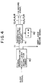
- an HD record signal at numerals 12 - 19 needs to be generated by providing a circuit arrangement in which the output 11 of a signal processing circuit 40 for the deep-layer record PCM format is converted into the 4 segments/field formation by a segmenting/interleaving circuit 41.
- the output of the signal processing circuit 40 may be used directly.
- a RAM 42 functions as a buffer which the segmenting/interleaving circuit 41 uses for its processing.
- one subframe indicated at numeral 3 is composed of fifteen superblocks.
- three superblocks forming an error correcting parity C2 indicated at numeral 22 are extracted, and the remaining twelve superblocks of PCM data are divided into three parts, each consisting of four superblocks.
- the part of four superblocks as denoted by numeral 2 is referred to as an "area block".
- the data of 1 frame can be divided into even data and odd data each consisting of fifteen area blocks, that is, the PCM data consisting of thirty area blocks in total, and the parity codes C2 of thirty superblocks.
- each of the segments 12 - 19 of the HD VTR system is formed of forty blocks (twenty super-blocks), of which the first 8 superblocks are set as an even data area 51, the last 8 superblocks as an odd data area 53, and the middle 4 superblocks as a parity C2 area 52.
- the even data and the odd data each consisting of 2 area blocks can be arranged in one segment, so that the PCM data of the even data and the odd data each consisting of 16 area blocks can be recorded in one frame according to the format shown in Fig. 1 (c).
- thirty area blocks of each frame of the deep-layer record signal 11 are turned into 32 area blocks by affixing dummy data 50 of 2 blocks thereto, and the 32 area blocks are arranged in the 16 area blocks of the even data area 51 of the HD VTR and those of the odd data area 53.
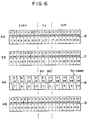
- two dummy C2 data items 60 in Fig. 6 to be referred to later
- the resulting thirty-two superblocks of the C2 data are divided into eight data items each consisting of four superblocks, and these data items are distributed to the respective eight segments.
- Fig. 1(c) The arrangement of the area blocks based on the above expedients (a) - (f) is as exemplified in Fig. 1(c).
- the three area blocks of the first even subframe E01 in the deep-layer record signal 11 are respectively located in the three segments 1A, 1B and 2A as stated before, and those of the odd subframe O01 in the second data frame are respectively located in the segments 2A, 2B and 1A.
- the requirement (2) is met. Even when the reproduction of the data of one segment is defective, the completion of the error correction with the three segments warrants the presence of data for the normal error correction within one field. If the error correction is completed with four segments, all error corrections in one field become impossible.
- the AV delay in the requirement (5) can be shortened.
- the data frame composed of the subframes E03 and O02 are located astride two fields in the HD VTR system.
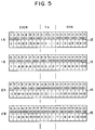
- Fig. 5 and Fig. 6 show an example of the detailed format of the first field consisting of the segments 1A, 1B, 2A and 2B and the latter field consisting of the segments 3A, 3B, 4A and 4B of the segmented signal, respectively.
- numerals at the lower stages of the segments "0" - “2” denote the superblocks belonging to the error correcting codes C2 (22), "3” - “6” denote those belonging to the first area blocks 1 in the subframes, "7” - "10” denote those belonging to the middle area blocks 2, and "11” - "14” denote those belonging to the last area blocks3.
- the superblocks of the subframe O02 are arranged in the segments 1B, 2B and 3A in consideration of the requirement (c).
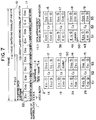
- that part O02 2 of the subframe O02 which ought to appear in the latter half of one frame is included in the segment 1B of the first-half segment group. Due to this fact, the generation of the segment 1B must wait until the latter half of the frame. As a result, the AV delay lengthens disadvantageously.
- the area block O02 2 is located in the segment 4A as shown in Fig. 7(c), whereby the AV delay can be shortened.
- the magnitude of the AV delay becomes 1 frame plus 11 milliseconds or so.
- the data frame to be subjected to an error correction includes the subframes O02 and E03, so that the error correction must be completed with the four segments 1B, 2B, 3A and 4A.
- Figs. 8(a) - 8(c) illustrate an example of a method in which two area blocks are recorded in duplicate without forming any dummy data.
- the area blocks E04 3 and O03 3 are duplicated. This method has the advantages that the completion of an error correction with three segments is held and that, even when the reproduction of one of the data items has become defective, the other data item can be used.
- the present invention is also applicable to a system whose frame is of 25 Hz.
Landscapes
- Engineering & Computer Science (AREA)
- Signal Processing (AREA)
- Multimedia (AREA)
- Signal Processing For Digital Recording And Reproducing (AREA)
Applications Claiming Priority (2)
| Application Number | Priority Date | Filing Date | Title |
|---|---|---|---|
| JP52184/91 | 1991-03-18 | ||
| JP3052184A JPH04286774A (ja) | 1991-03-18 | 1991-03-18 | Pcm信号記録方式 |
Publications (3)
| Publication Number | Publication Date |
|---|---|
| EP0504849A2 true EP0504849A2 (de) | 1992-09-23 |
| EP0504849A3 EP0504849A3 (en) | 1994-11-23 |
| EP0504849B1 EP0504849B1 (de) | 1997-02-05 |
Family
ID=12907719
Family Applications (1)
| Application Number | Title | Priority Date | Filing Date |
|---|---|---|---|
| EP92104701A Expired - Lifetime EP0504849B1 (de) | 1991-03-18 | 1992-03-18 | PCM-Signal Aufzeichnungssystem |
Country Status (4)
| Country | Link |
|---|---|
| US (1) | US5260840A (de) |
| EP (1) | EP0504849B1 (de) |
| JP (1) | JPH04286774A (de) |
| DE (1) | DE69217262T2 (de) |
Cited By (2)
| Publication number | Priority date | Publication date | Assignee | Title |
|---|---|---|---|---|
| EP0813197A3 (de) * | 1996-06-14 | 1998-07-08 | Samsung Electronics Co., Ltd. | System zur Aufzeichnung und/oder Wiedergabe eines digitalen Audiopulskodemodulationssignals |
| RU2267171C2 (ru) * | 1999-08-13 | 2005-12-27 | Конинклейке Филипс Электроникс Н.В. | Передача цифрового информационного сигнала, имеющего м битовые выборки икм |
Families Citing this family (7)
| Publication number | Priority date | Publication date | Assignee | Title |
|---|---|---|---|---|
| US5488517A (en) * | 1992-10-08 | 1996-01-30 | U.S. Philips Corporation | System comprising a magnetic-tape cassette and a magnetic-tape apparatus, and magnetic-tape cassette, tape-cleaning means and tape-cleaning element for use in the system |
| KR0147575B1 (ko) * | 1992-11-27 | 1998-09-15 | 김광호 | 영상신호의 기록포맷과 심층기록/재생장치 및 그 방법 |
| KR940018849A (ko) * | 1993-01-28 | 1994-08-19 | 프레데릭 얀 스미트 | 영상신호 및 이에 대응하는 음성 신호를 길이방향 자기 기록 매체상의 경사기록 트랙에 기록하는 장치 및 기록매체 (Arrangement for recording a video signal and a corresponding audio signal in slant tracks on a longitudinal magnetic record carrier, and record carrier obtained by means of the arrangement) |
| KR970010533B1 (en) * | 1994-06-30 | 1997-06-26 | Samsung Electronics Co Ltd | Recording and reproducing method of dvcr for trick play |
| US6728920B1 (en) * | 1999-05-24 | 2004-04-27 | Adaptive Broadband Corporation | Method for correcting errors in transfer of information |
| US6972683B2 (en) * | 2001-07-20 | 2005-12-06 | Hill-Rom Services, Inc. | Badge for a locating and tracking system |
| US10734110B2 (en) | 2018-12-05 | 2020-08-04 | Hill-Rom Services, Inc. | Caregiver locating tag having advanced functionality |
Family Cites Families (9)
| Publication number | Priority date | Publication date | Assignee | Title |
|---|---|---|---|---|
| JPH07118160B2 (ja) * | 1983-06-18 | 1995-12-18 | ソニー株式会社 | ディジタル情報信号の記録方法 |
| JPH07101541B2 (ja) * | 1983-06-28 | 1995-11-01 | ソニー株式会社 | デイジタル情報信号の記録装置 |
| JPH07122966B2 (ja) * | 1984-03-19 | 1995-12-25 | 株式会社日立製作所 | 回転ヘッド型pcmレコーダの記録方法及び再生方法 |
| KR900008446B1 (ko) * | 1985-11-13 | 1990-11-22 | 가부시끼가이샤 히다찌세이사꾸쇼 | 음성신호를위한표본화주파수와회전헤드스캔너의회전주파수사이에서비동기관계를갖는음성신호의pcm기록재생장치 |
| US5068752A (en) * | 1987-09-29 | 1991-11-26 | Matsushita Electric Industrial Co., Ltd. | Apparatus for recording/reproducing a digital audio signal with a video signal |
| US5144500A (en) * | 1988-01-08 | 1992-09-01 | Sony Corporation | Method and apparatus for reproducing multiply recorded data |
| JP2675085B2 (ja) * | 1988-07-20 | 1997-11-12 | 株式会社日立製作所 | 回転ヘッド形pcmレコーダの記録再生方法 |
| DE69023808T2 (de) * | 1989-05-12 | 1996-08-08 | Mitsubishi Electric Corp | Verfahren und Aufzeichnungs- und Wiedergabegerät mit einem rotierenden Kopf. |
| DE3916892A1 (de) * | 1989-05-24 | 1990-11-29 | Linde Ag | Verfahren und vorrichtung zur entnahme von gasen aus speicherbehaeltern |
-
1991
- 1991-03-18 JP JP3052184A patent/JPH04286774A/ja active Pending
-
1992
- 1992-03-16 US US07/851,879 patent/US5260840A/en not_active Expired - Fee Related
- 1992-03-18 DE DE69217262T patent/DE69217262T2/de not_active Expired - Fee Related
- 1992-03-18 EP EP92104701A patent/EP0504849B1/de not_active Expired - Lifetime
Cited By (2)
| Publication number | Priority date | Publication date | Assignee | Title |
|---|---|---|---|---|
| EP0813197A3 (de) * | 1996-06-14 | 1998-07-08 | Samsung Electronics Co., Ltd. | System zur Aufzeichnung und/oder Wiedergabe eines digitalen Audiopulskodemodulationssignals |
| RU2267171C2 (ru) * | 1999-08-13 | 2005-12-27 | Конинклейке Филипс Электроникс Н.В. | Передача цифрового информационного сигнала, имеющего м битовые выборки икм |
Also Published As
| Publication number | Publication date |
|---|---|
| DE69217262T2 (de) | 1997-08-28 |
| EP0504849A3 (en) | 1994-11-23 |
| US5260840A (en) | 1993-11-09 |
| DE69217262D1 (de) | 1997-03-20 |
| EP0504849B1 (de) | 1997-02-05 |
| JPH04286774A (ja) | 1992-10-12 |
Similar Documents
| Publication | Publication Date | Title |
|---|---|---|
| KR920008229B1 (ko) | 디지탈정보신호의 기록방법 | |
| US5012352A (en) | Digital signal recording apparatus time-division multiplexing video and audio signals | |
| EP0203773B1 (de) | Anordnung zur Dekodierung eines Fehler korrigierenden Codes | |
| US4882732A (en) | Method and apparatus for recording and/or reproducing digital data | |
| US5113293A (en) | Magnetic recorder/reproducer | |
| EP0542576B1 (de) | Vorrichtung und Verfahren zum Aufnehmen und Wiedergeben von digitalen Video- und Audiosignalen | |
| KR900000630B1 (ko) | 정지헤드로서 디지탈신호의 기록 및 재생을 위한 방법과 그 장치 | |
| KR850001677B1 (ko) | Pcm신호 기록방법 | |
| US4630272A (en) | Encoding method for error correction | |
| US4622600A (en) | Rotary-head type PCM data recording/reproducing method and apparatus with a redundancy-reduced control data format | |
| EP0074644B1 (de) | A PCM-Aufzeichnungs- und Wiedergabeanordnung mit einem datenfehlerfreien Format | |
| US4364081A (en) | Method and apparatus for processing a digital color video signal | |
| EP0504849B1 (de) | PCM-Signal Aufzeichnungssystem | |
| US5101274A (en) | Digital signal recording apparatus time-division multiplexing video and audio signals | |
| US5432613A (en) | Image data processing apparatus and method for processing image data | |
| US5809209A (en) | Video signal recording apparatus with varying interleaving of digital video signals | |
| JPS6333748B2 (de) | ||
| US4918694A (en) | Method and apparatus for correction of errors in digital audio data | |
| JP2738257B2 (ja) | ディジタル音声信号記録方法および記録装置 | |
| JP3103565B2 (ja) | ビデオ信号処理方法 | |
| JP3259298B2 (ja) | ディジタル画像信号の記録装置 | |
| GB2275151A (en) | Image data processing for digital video tape recorder | |
| JPS5990440A (ja) | デ−タ伝送装置 | |
| JPH0810540B2 (ja) | デイジタル信号記録方式 | |
| JPS6151348B2 (de) |
Legal Events
| Date | Code | Title | Description |
|---|---|---|---|
| PUAI | Public reference made under article 153(3) epc to a published international application that has entered the european phase |
Free format text: ORIGINAL CODE: 0009012 |
|
| 17P | Request for examination filed |
Effective date: 19920318 |
|
| AK | Designated contracting states |
Kind code of ref document: A2 Designated state(s): DE FR GB |
|
| PUAL | Search report despatched |
Free format text: ORIGINAL CODE: 0009013 |
|
| AK | Designated contracting states |
Kind code of ref document: A3 Designated state(s): DE FR GB |
|
| RHK1 | Main classification (correction) |
Ipc: G11B 20/12 |
|
| GRAG | Despatch of communication of intention to grant |
Free format text: ORIGINAL CODE: EPIDOS AGRA |
|
| 17Q | First examination report despatched |
Effective date: 19960326 |
|
| GRAH | Despatch of communication of intention to grant a patent |
Free format text: ORIGINAL CODE: EPIDOS IGRA |
|
| GRAH | Despatch of communication of intention to grant a patent |
Free format text: ORIGINAL CODE: EPIDOS IGRA |
|
| GRAA | (expected) grant |
Free format text: ORIGINAL CODE: 0009210 |
|
| AK | Designated contracting states |
Kind code of ref document: B1 Designated state(s): DE FR GB |
|
| REF | Corresponds to: |
Ref document number: 69217262 Country of ref document: DE Date of ref document: 19970320 |
|
| ET | Fr: translation filed | ||
| PLBE | No opposition filed within time limit |
Free format text: ORIGINAL CODE: 0009261 |
|
| 26N | No opposition filed | ||
| PGFP | Annual fee paid to national office [announced via postgrant information from national office to epo] |
Ref country code: GB Payment date: 19980306 Year of fee payment: 7 |
|
| PGFP | Annual fee paid to national office [announced via postgrant information from national office to epo] |
Ref country code: FR Payment date: 19980316 Year of fee payment: 7 |
|
| PGFP | Annual fee paid to national office [announced via postgrant information from national office to epo] |
Ref country code: DE Payment date: 19980428 Year of fee payment: 7 |
|
| PG25 | Lapsed in a contracting state [announced via postgrant information from national office to epo] |
Ref country code: GB Free format text: LAPSE BECAUSE OF NON-PAYMENT OF DUE FEES Effective date: 19990318 |
|
| GBPC | Gb: european patent ceased through non-payment of renewal fee |
Effective date: 19990318 |
|
| PG25 | Lapsed in a contracting state [announced via postgrant information from national office to epo] |
Ref country code: FR Free format text: LAPSE BECAUSE OF NON-PAYMENT OF DUE FEES Effective date: 19991130 |
|
| REG | Reference to a national code |
Ref country code: FR Ref legal event code: ST |
|
| PG25 | Lapsed in a contracting state [announced via postgrant information from national office to epo] |
Ref country code: DE Free format text: LAPSE BECAUSE OF NON-PAYMENT OF DUE FEES Effective date: 20000101 |