EP0504841B1 - Ultraschallbündelungs-Empfängeranordnung - Google Patents
Ultraschallbündelungs-Empfängeranordnung Download PDFInfo
- Publication number
- EP0504841B1 EP0504841B1 EP92104689A EP92104689A EP0504841B1 EP 0504841 B1 EP0504841 B1 EP 0504841B1 EP 92104689 A EP92104689 A EP 92104689A EP 92104689 A EP92104689 A EP 92104689A EP 0504841 B1 EP0504841 B1 EP 0504841B1
- Authority
- EP
- European Patent Office
- Prior art keywords
- signal
- channel
- delay line
- multiplication
- ultrasonic
- Prior art date
- Legal status (The legal status is an assumption and is not a legal conclusion. Google has not performed a legal analysis and makes no representation as to the accuracy of the status listed.)
- Expired - Lifetime
Links
Images



Classifications
-
- G—PHYSICS
- G10—MUSICAL INSTRUMENTS; ACOUSTICS
- G10K—SOUND-PRODUCING DEVICES; METHODS OR DEVICES FOR PROTECTING AGAINST, OR FOR DAMPING, NOISE OR OTHER ACOUSTIC WAVES IN GENERAL; ACOUSTICS NOT OTHERWISE PROVIDED FOR
- G10K11/00—Methods or devices for transmitting, conducting or directing sound in general; Methods or devices for protecting against, or for damping, noise or other acoustic waves in general
- G10K11/18—Methods or devices for transmitting, conducting or directing sound
- G10K11/26—Sound-focusing or directing, e.g. scanning
- G10K11/34—Sound-focusing or directing, e.g. scanning using electrical steering of transducer arrays, e.g. beam steering
- G10K11/341—Circuits therefor
- G10K11/346—Circuits therefor using phase variation
Definitions
- the present invention relates to an ultrasonic reception beam former according to the preamble of claim 1.
- US-A-4 290 127 discloses a beam former for an array of sonar transducers, or electromagnetic radiating elements, including mixers for translating the signals received by the transducers to a lower frequency.
- This known beam former incorporates delay lines operating at a clock rate which is reduced in proportion to the decrease in frequency. Each delay line provides delays to the signals of corresponding ones of the transducers in accordance with the time of arrival of a wave front of radiation upon the respective transducers.
- Phase shifters coupled between the mixers and the delay lines impart phase shifts to the transducer signals proportional to the respective delays to compensate for the lowering of the frequency.
- a plurality of transducers arranged on the surface of an ultrasonic probe are operated to convert a received ultrasonic wave signal into an electric signal.
- the electric signal from each transducer is amplified by the receiving amplifier corresponding to each transducer and fed into the delay line alloted to each transducer.
- the delay time of each delay line is adjusted to regulate focussing so that the signals reflected from a specified point of a human body are received by each transducer and output at the same time at the output terminals of delay lines.
- Fig. 1 shows a mode of a fixed focussing system in a conventional ultrasonic wave reception.
- Reference numeral 1 in Fig. 1 denotes an ultrasonic probe, 2-i respective transducers, 3-i delay lines, T-i terminals and A an ultrasonic wave reflection point. In this figure, receiving amplifiers are not depicted.
- the ultrasonic wave signal reflected from the point A is received by the transducers 2-i and each of said transducers 2-i converts the wave signal to an electric signal.
- the delay line 3-i is disposed for the transducer 2-i in order to correct this distance difference
- the difference of the distance is corrected so that ultrasonic signals emitted from the point A at the same time, are received and converted by the respective transducers 2-i, and appear simultaneously at each terminal T-i.
- the delay time in the above-noted delay lines 3-i must be adjusted again whenever the position of the ultrasonic wave reflection point A becomes different.
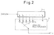
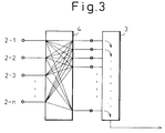
- Figs. 2 and 3 show a different type of structure of the delay line shown in Fig. 1, respectively.
- reference numerals 3 and 3-i denote the delay line
- reference numeral 4 does a multiplexer.
- symbol T-i denotes a terminal that corresponds to the terminal shown in Fig. 1.
- one delay line 3-i is provided to each channel (the channel corresponding to each transducer 2-i) shown in Fig. 1, and the delay time described above is adjusted, in principle, by a multiplexer 4.
- a single delay line 3 equipped with taps is provided for a plurality of channels, and the terminals 2-i and T-i shown in Fig. 1 and corresponding to the respective channels are connected to the multiplexer 4.
- the multiplexer 4 is constituted such that the signal connected to the terminal on the input side can be changeably connected to each terminal on the output side.
- the connection state described above is switched and set depending on which input terminal should be guided to any transducer output.
- the delay time described above is decided in advance correctly, and a desired delay time is given to the signal from each channel at the output terminal of the delay line. The signals are then added together.
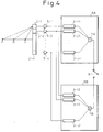
- Fig. 4 shows an example of a two-route alternate switching system.
- Reference numerals 2-i, 3-i and A in Fig. 4 represent the same members as in Fig. 1.
- Reference numeral 5-i denotes amplifiers
- 6A and 6B delay line units for subsequent reflection points #1 and #2
- 7A and 7B denote adders
- 8 is a selector switch
- B and C denote other reflection points.
- the delay lines 3-i shown in Fig. 1 are sequentially and altogether changed over as the position of the reflection point becomes different, in a manner as to attain the corresponding delay time, respectively.
- the units 6A and 6B are separately disposed so that while the unit 6A is adjusted so as to detect the ultrasonic wave signal from the refection point A or in other words, while the switch 8 is connected to the unit 6A side, the delay lines 3-i2 are together adjusted in the unit 6B so that the ultrasonic wave signal from the reflection point B can be detected next in the unit 6B. While this unit 6B detects the ultrasonic wave signal from the reflection point B, the delay lines 3-il in the unit 6A are together adjusted so that the ultrasonic wave signal from the reflection point C can be detected next in the unit 6A.
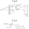
- Fig. 5 shows an example of the case of a phase control system (Refer to U.S. Patent No. 4140022).
- Reference numerals 2-i, 3, 5-i and A i the drawing correspond to those used in Figs. 1, 3 and 4, respectively.
- Reference numeral 9-i denotes a signal waveform.
- the difference of the distance from the reflection point A is corrected by the delay lines 3-i.
- the focus is adjusted to the reflection point A, if the positive peak point of the alternate signal appearing, for example, at the terminal T-1 in Fig. 1, can be synthesized so as to superpose with the positive peak points of the alternate signals appearing at the terminals T-2, T-3, ..., even though the correction for eliminating the difference of the distance described above is not made.
- the phase control system shown in Fig. 5 utilizes this principle.
- the difference of the time t exists between the signal 9-1 from the transducer 2-1 and the signal 9-p from the transducer 2-p at the start as shown in the drawing.
- the positive peak point of the signal 9-1 does not always coincide with the positive peak point of the signal 9-p and my come to have an opposite phase, on as the case may be.
- the phase control system shown in Fig. 5 is provided with a means for adjusting the phase of the signal 9-p, for example, and bringing it into conformity with the phase of the signal 9-1, though said means is omitted from Fig. 5.
- Fig. 6 shows the operation of the phase adjustment means.
- Reference numeral 10 denotes a multiplier. It will be hereby assumed that cos ( ⁇ t + ⁇ ) is supplied as the input signal, and cos ( ⁇ t + ⁇ ) is supplied as the reference signal. In this case, the output signal of the multiplier 10 is given as follows: 1/2 [cos ⁇ ( ⁇ + ⁇ )t + ⁇ + ⁇ ⁇ + cos ⁇ - ⁇ )t + ⁇ - ⁇ ]
- this after-multiplication channel signal is given by cos ⁇ ( ⁇ - ⁇ )t + ⁇ - ⁇ . It can thus be appreciated that the phase of the after-multiplication channel single can be changed by adjusting the phase in the reference signal.
- phase adjustment on the basis of the principle shown in Fig. 6 is applied to the signal 9-p, for example, so that its positive peak may be in conformity with that of the signal 9-1.
- the affected part are scanned while the ultrasonic wave is generated, and the reflected wave is received.
- the diagnosis is carried out by transmitting the ultrasonic wave in a certain direction, receiving the reflected wave, transmitting the ultrasonic wave in the next direction to receive a reflected wave, and repeating these procedures. Therefore, the scanning time is made longer.
- a simultaneous multi-directional reception system has been known in the past in order to improve this problem.
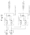
- Fig. 12 shows a typical simultaneous multi-directional reception system. After the outputs of transducers are amplified, and outputs of direction "1" are summed up, by an adder 104-1 to create a final output for a direction "1", whereas outputs of direction "2" are summed up by an adder 104-2 to create a final output for a direction "2".
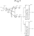
- Fig. 7 shows the operation of the simultaneous multi-directional reception system
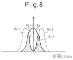
- Fig. 8 is a view showing sound pressure vs. direction characteristics in Fig. 7.
- Reference numerals 2-i, 5-i, Ai and Bi correspond to those used in Fig. 1, etc.
- Reference numeral 11 denotes a transmission direction of the ultrasonic wave
- 12-1 and 12-2 are reception directions
- 13-1 and 13-2 are focussing units, respectively.
- a first direction focussing unit 13-1 is so set as to receive a reflection from a point A1 in the direction 12-1 and a second direction focussing unit 13-2 is set so as to receive a reflection from a point A2 in the direction 12-2 shown in the drawing.
- dynamic focussing is effected in the respective focussing units 13-i in a manner so as to receive the reflection from the point B1 or B2 in the same direction.
- Fig. 8 is a drawing explaining the principle of the simultaneous multi-directional reception.
- Reference numeral 14 in Fig. 8 denotes transmission directivity characteristics towards the direction 11, reference numeral 15-1 reception directivity characteristics towards the direction 12-1 and reference numeral 15-2 reception directivity characteristics towards the direction 12-2.
- the directivity characteristics described above are characteristics 14 and 15-1 as shown, respectively, the directivity characteristics of the signal received by the transducer 2-i become the overall reception characteristics as represented by reference numeral 16-i in Fig. 8. It is possible to consider that the first direction focussing unit 13-1 and the second direction focussing unit 13-2 are arranged in a manner so as to match the characteristics 16-1 and 16-2 shown in the drawing, respectively.
- the above quantity becomes "2" even when the phase control system is employed, if the simultaneous multi-directional reception system is used after accomplishing dynamic focussing.
- the present invention is directed to solve these problems, and an object of the present invention is to provide an ultrasonic wave reception beam system that makes it possible to employ dynamic focussing and at the same time, to apply a simultaneous multi-directional reception system, while the number of necessary delay lines is kept on as "1".
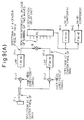
- Fig. 9(A) is an outlined view showing the configuration of the present invention
- Fig. 9(B) shows band characteristics of each filter and an output of a transducer.
- Reference numeral 17-i represents a band-pass filter
- 18 is an adder
- 19-i is a band-pass filter.
- Reference numeral 20 represents frequency band characteristics of a signal from the transducer 2-i
- 21-1 represents frequency band characteristics of a signal from the filter 17-1
- Fig. 9(A) can be considered as typifying the structure from one transducer 2-i (or in other words, a structure corresponding to one channel).
- a first reference signal cos ( ⁇ t + ⁇ 1 ) and a second reference signal cos ( ⁇ t + ⁇ 2 ) are selected so that an angular frequency ⁇ and an angular frequency ⁇ have mutually different values for the purpose of discriminating reception signals corresponding to mutually different two directions, respectively, when a simultaneous multi-directional reception system is employed.
- phase angle ⁇ of the first reference signal and the phase angle ⁇ of the second reference signal are represented by the same symbol, but in particular, they comprise the combination of (i) phase angles ⁇ , ⁇ ' for providing directional characteristics corresponding to mutually different directions when the simultaneous multi-directional reception system is employed, and (ii) the change of the phase angle ⁇ (t) for effecting a dynamic focus by a phase control system.
- the filter 17-1 and the filter 19-1 are band-pass filters for extracting a component having a frequency ( ⁇ - ⁇ )/2 ⁇ , respectively, and the filter 17-2 and the filter 19-2 are band-pass filters for extracting a component of a frequency ( ⁇ - ⁇ )/2 ⁇ , respectively.
- the output from a multiplier 10-il has a component having the frequency ( ⁇ + ⁇ )/2 ⁇ and a component having the frequency ( ⁇ - ⁇ )/2 ⁇ .
- the output from a multiplier 10-i2 has a component having the frequency ( ⁇ + ⁇ )/2 ⁇ and a component having the frequency ( ⁇ - ⁇ )/2 ⁇ .
- the output of the filter 17-1 has only a component having the frequency ( ⁇ - ⁇ )/2 ⁇ and the output of the filter 17-2 has only a component having the frequency ( ⁇ - ⁇ )/2 ⁇ .
- the former carries reception data from the first direction in the simultaneous multi-directional reception system and the latter likewise carries the reception data from the second direction.
- both of them are superposed by the adder 18, and are then guided to a delay line 3 as an after-multiplication channel signal corresponding to one channel. After being subjected to time matching with similar after-multiplication channel signals from other channels, these signals are added together and output.
- the output from the delay line 3 is segmented to the components having the respective frequency components by the band-pass filter 19-i.
- the output from the filter 19-1 is the sum of the "first direction after-multiplication channel signals", which carry the reception information from the first direction in each of the channels, for all the channels.
- the output from the filter 19-2 is similarly the sum of the "second direction after-multiplication channel signals", which carry the reception information from the second direction in each of the channels, for all the channels.
- each filter 19-i comes to possess informaiton of the result of the dynamic focus by changing the above-mentioned values ⁇ (t) and ⁇ '(t) at the phase angle ⁇ in the reference signal.
- the band characteristics of the signal from the transducer 2-i are represented by reference numeral 20 in Fig. 9(B)
- the band characteristics of the output from the filter 17-1 are represented by reference numeral 21-1 in the drawing
- the band characteristics of the output from the filter 17-2 are represented by reference numeral 21-2 in the drawing.
- the number of the delay line may be only "one" even though the simultaneous multi-directional reception system is employed and dynamic focussing is effected.
- Fig. 11 shows the structure of an embodiment of the present invention.
- reference numerals 2, 3, 4, 5, 10, 17, 18 and 19 correspond to the reference numerals used in Fig. 9(A) respectively.
- the frequency of the first reference signal in the first channel corresponding to the transducer 2-1, ...., and the frequency of the first reference signal in the n th channel corresponding to the transducer 2-n are the same.
- first reference signal ... ⁇ (1) ⁇ (1) + ⁇ (1, t)
- second reference signal .. ⁇ (1) ⁇ '(1) + ⁇ '(1, t)
- phase of the two reference signals in the n th channel are as follows, as explained with reference to Fig. 9(A).
- first reference signal ... ⁇ (n) ⁇ (n) + ⁇ (n, t)
- second reference signal .. ⁇ '(n) ⁇ '(n) + ⁇ '(n, t)
- the frequency components of the two signals added in the adder 18-i can preferably be separated from each other.
- the frequency components of the output at the filter 19-i are mutually separated.
- the adder 18 and the adder 18-i in Figs. 9(A) and 11 are not always indispensable but can be omitted, whenever necessary, if suitable measures are taken.
- the directions 11, 12-i shown in Fig. 7, for example, in the case of the simultaneous mutli-directional reception system, are changed by scanning with the passage of time as represented by a blank arrow. Therefore, in the case of Figs. 9 and 11, scanning as described above is carried out by changing the angles ⁇ (i) and ⁇ '(i) with the time and/or by changing the switch position by the multiplexer 4.
- the frequency separation of the spectra of two intermediate frequency signals having multi-directional directivity cannot be made by a simple mixer because the band width of the reception signal is not zero, the frequency separation may of course be carried out by a double heterodyne system.
- the number of the delay line is only "one", although the simultaneous multi-directional reception system is employed and dynamic focussing is carried out.
Landscapes
- Physics & Mathematics (AREA)
- Engineering & Computer Science (AREA)
- Acoustics & Sound (AREA)
- Multimedia (AREA)
- Investigating Or Analyzing Materials By The Use Of Ultrasonic Waves (AREA)
- Ultra Sonic Daignosis Equipment (AREA)
- Measurement Of Velocity Or Position Using Acoustic Or Ultrasonic Waves (AREA)
- Transducers For Ultrasonic Waves (AREA)
Claims (6)
- Ultraschallempfangsstrahlformer mit einer Ultraschallsonde (1), die mit mehreren Transducern (2-i) ausgestattet ist und jeweilig entsprechende mehrere Kanäle aufweist, wobei jeder Transducer ein Ultraschallsignal, das von einer Zielposition reflektiert wird und dadurch empfangen wird, in ein elektrisches Kanalsignal umwandelt, und das System eine dynamische Fokussierung ausführt und aufweist:mindestens erste und zweite Referenzsignale, die jeweilige und wechselseitig unterschiedliche Frequenzen und dynamisch eingestellte Phasen aufweisen, und mindestens erste und zweite jeweilige Multiplizierer (10-np) für jeden der Kanäle vorgesehen sind, wobei jeder Multiplizierer das jeweilige Referenzsignal als eine erste Eingangsgröße dafür empfängt, jeder Multiplizierer an seinem zweiten Eingang das entsprechende elektrische Kanalsignal empfängt und es mit dem jeweiligen Referenzsignal multipliziert und ein entsprechendes Nach-Multiplikationskanalsignal als dessen Ausgangsgröße erzeugt;jedes der Referenzsignale so zusammengesetzt ist, daß es einem Ultraschallsignal entspricht und es diskriminiert, wie es durch den entsprechenden Transducer aus einer entsprechenden Richtung empfangen wird, das sich von anderen solchen Ultraschallsignalen unterscheidet, die durch den entsprechenden Transducer aus jeweiligen anderen entsprechenden Richtungen empfangen werden, und daß dessen Phasenwinkel Θ(i) so eingestellt ist, daß eine dynamische Fokussierung ausgeführt wird;das Nach-Multiplikationskanalsignal aus jedem der Multiplizierer (10-np) für jeden Kanal nach dessen Verarbeitung durch einen jeweiligen Frequenztrennungsfilter (17-np) einer einzigen Verzögerungsleitung (3) zugeführt wird; unddie Nach-Multiplikationskanalsignale für die jeweiligen mehreren Kanäle, in der Verarbeitung durch die Verzögerungsleitung zum Erzeugen eines endgültigen überlagerten Ausgangssignals der Verzögerungsleitung zeitverschoben und zueinander addiert werden, das einer Frequenztrennung durch mindestens erste und zweite Filter (10) unterworfen wird, die jeweils angepaßt sind, den wechselseitig unterschiedlichen Frequenzen der mindestens ersten und zweiten Referenzsignale zu entsprechen.
- Ultraschallempfangsstrahlformer nach Anspruch 1, wobei die jeweiligen Frequenzen der mindestens ersten und zweiten Referenzsignale so ausgewählt werden, daß die Frequenzbänder der Nach-Multiplikationskanalsignale, die aus den jeweiligen Multiplizierern (10) in jedem der mehreren Kanäle erhalten werden, sich nicht wesentlich gegenseitig überlappen.
- Ultraschallempfangsstrahlformer nach Anspruch 1 oder 2, wobei das Nach-Multiplikationssignal aus jedem der Multiplizierer (10) in jedem der Kanäle durch die jeweiligen Frequenztrennungsfilter (17-np) so gefiltert wird, daß nur ausgewählte Frequenzkomponenten extrahiert werden, und dann der Verzögerungsleitung (3) zugeführt wird.
- Ultraschallempfangsstrahlformer nach Anspruch 3, wobei innerhalb jedes Kanals, die ausgewählten Frequenzkomponenten, die durch jeden Frequenztrennungsfilter (17-np) extrahiert werden, so ausgewählt werden, daß das Frequenzband des Nach-Multiplikationskanalsignals nach dem Filtern sich nicht wesentlich mit dem Frequenzband irgendeines anderen der Nach-Multiplikationskanalsignale des Kanals überlappt.
- Ultraschallempfangsstrahlformer nach einem der vorhergehenden Ansprüche, wobei die Verzögerungsleitung (3) mehrere Anzapfungen aufweist, und die Nach-Multiplikationskanalsignale der jeweiligegen Kanäle den Anzapfungen der Verzögerungsleitung (3) durch einen Multiplexer (4) zugeführt werden.
- Ultraschallwellenempfangsstrahlformer nach einem der Ansprüche 1, 2, 3, 4 oder 5, wobei die jeweiligen mindestens zwei Nach-Multiplikationskanalsignale in jedem der Kanäle miteinander überlagert werden, bevor sie der Verzögerungsleitung (3) zugeführt werden und das überlagerte Nach-Multiplikationssignal jedes Kanals dann der Verzögerungsleitung (3) zugeführt wird.
Applications Claiming Priority (2)
| Application Number | Priority Date | Filing Date | Title |
|---|---|---|---|
| JP3057275A JPH04291185A (ja) | 1991-03-20 | 1991-03-20 | 超音波受信ビームフォーマ |
| JP57275/91 | 1991-03-20 |
Publications (3)
| Publication Number | Publication Date |
|---|---|
| EP0504841A2 EP0504841A2 (de) | 1992-09-23 |
| EP0504841A3 EP0504841A3 (en) | 1993-05-12 |
| EP0504841B1 true EP0504841B1 (de) | 1998-06-10 |
Family
ID=13050987
Family Applications (1)
| Application Number | Title | Priority Date | Filing Date |
|---|---|---|---|
| EP92104689A Expired - Lifetime EP0504841B1 (de) | 1991-03-20 | 1992-03-18 | Ultraschallbündelungs-Empfängeranordnung |
Country Status (4)
| Country | Link |
|---|---|
| US (1) | US5228007A (de) |
| EP (1) | EP0504841B1 (de) |
| JP (1) | JPH04291185A (de) |
| DE (1) | DE69225824T2 (de) |
Families Citing this family (26)
| Publication number | Priority date | Publication date | Assignee | Title |
|---|---|---|---|---|
| JP3322694B2 (ja) * | 1992-05-25 | 2002-09-09 | 株式会社日立メディコ | 超音波撮像装置 |
| US5675554A (en) * | 1994-08-05 | 1997-10-07 | Acuson Corporation | Method and apparatus for transmit beamformer |
| US5928152A (en) * | 1994-08-05 | 1999-07-27 | Acuson Corporation | Method and apparatus for a baseband processor of a receive beamformer system |
| DE19581718T5 (de) * | 1994-08-05 | 2013-11-07 | Siemens Medical Solutions USA, Inc. (n.d. Ges. d. Staates Delaware) | Verfahren und Vorrichtung für Sendestrahlformersystem |
| US6029116A (en) * | 1994-08-05 | 2000-02-22 | Acuson Corporation | Method and apparatus for a baseband processor of a receive beamformer system |
| US5793701A (en) * | 1995-04-07 | 1998-08-11 | Acuson Corporation | Method and apparatus for coherent image formation |
| US5685308A (en) * | 1994-08-05 | 1997-11-11 | Acuson Corporation | Method and apparatus for receive beamformer system |
| US5469851A (en) * | 1994-08-09 | 1995-11-28 | Hewlett-Packard Company | Time multiplexed digital ultrasound beamformer |
| US5488588A (en) * | 1994-09-07 | 1996-01-30 | General Electric Company | Ultrasonic imager having wide-bandwidth dynamic focusing |
| US5600675A (en) * | 1994-09-07 | 1997-02-04 | General Electric Company | Ultrasonic imager having improved bandwidth |
| US6005827A (en) | 1995-03-02 | 1999-12-21 | Acuson Corporation | Ultrasonic harmonic imaging system and method |
| US6027448A (en) * | 1995-03-02 | 2000-02-22 | Acuson Corporation | Ultrasonic transducer and method for harmonic imaging |
| US5608690A (en) * | 1995-03-02 | 1997-03-04 | Acuson Corporation | Transmit beamformer with frequency dependent focus |
| US5678554A (en) * | 1996-07-02 | 1997-10-21 | Acuson Corporation | Ultrasound transducer for multiple focusing and method for manufacture thereof |
| US5532700A (en) * | 1995-03-16 | 1996-07-02 | The United States Of America As Represented By The Secretary Of The Navy | Preprocessor and adaptive beamformer for active signals of arbitrary waveform |
| US6111816A (en) * | 1997-02-03 | 2000-08-29 | Teratech Corporation | Multi-dimensional beamforming device |
| US6292433B1 (en) | 1997-02-03 | 2001-09-18 | Teratech Corporation | Multi-dimensional beamforming device |
| US6721235B2 (en) | 1997-02-03 | 2004-04-13 | Teratech Corporation | Steerable beamforming system |
| US6021093A (en) * | 1997-05-14 | 2000-02-01 | Gas Research Institute | Transducer configuration having a multiple viewing position feature |
| US6002639A (en) * | 1997-05-14 | 1999-12-14 | Gas Research Institute | Sensor configuration for nulling reverberations to image behind reflective layers |
| US5995447A (en) * | 1997-05-14 | 1999-11-30 | Gas Research Institute | System and method for processing acoustic signals to image behind reflective layers |
| US6125079A (en) * | 1997-05-14 | 2000-09-26 | Gas Research Institute | System and method for providing dual distance transducers to image behind an acoustically reflective layer |
| US5891037A (en) * | 1997-12-18 | 1999-04-06 | Acuson Corporation | Ultrasonic Doppler imaging system with frequency dependent focus |
| US6293912B1 (en) | 1999-06-10 | 2001-09-25 | B-K Medical A/S | Ultrasound scanner with beam former |
| US6842401B2 (en) | 2000-04-06 | 2005-01-11 | Teratech Corporation | Sonar beamforming system |
| US10343193B2 (en) | 2014-02-24 | 2019-07-09 | The Boeing Company | System and method for surface cleaning |
Family Cites Families (5)
| Publication number | Priority date | Publication date | Assignee | Title |
|---|---|---|---|---|
| US3950723A (en) * | 1974-02-21 | 1976-04-13 | Westinghouse Electric Corporation | Sonar apparatus |
| US4140022B1 (en) * | 1977-12-20 | 1995-05-16 | Hewlett Packard Co | Acoustic imaging apparatus |
| US4290127A (en) * | 1979-12-03 | 1981-09-15 | Raytheon Company | Beamformer with reduced sampling rate |
| US4662223A (en) * | 1985-10-31 | 1987-05-05 | General Electric Company | Method and means for steering phased array scanner in ultrasound imaging system |
| JPS6329280A (ja) * | 1986-07-23 | 1988-02-06 | Furuno Electric Co Ltd | ソナ−の指向性受波ビ−ム形成装置 |
-
1991
- 1991-03-20 JP JP3057275A patent/JPH04291185A/ja active Pending
-
1992
- 1992-03-18 EP EP92104689A patent/EP0504841B1/de not_active Expired - Lifetime
- 1992-03-18 DE DE69225824T patent/DE69225824T2/de not_active Expired - Fee Related
- 1992-03-20 US US07/854,887 patent/US5228007A/en not_active Expired - Fee Related
Also Published As
| Publication number | Publication date |
|---|---|
| EP0504841A3 (en) | 1993-05-12 |
| US5228007A (en) | 1993-07-13 |
| EP0504841A2 (de) | 1992-09-23 |
| DE69225824T2 (de) | 1998-10-15 |
| DE69225824D1 (de) | 1998-07-16 |
| JPH04291185A (ja) | 1992-10-15 |
Similar Documents
| Publication | Publication Date | Title |
|---|---|---|
| EP0504841B1 (de) | Ultraschallbündelungs-Empfängeranordnung | |
| US5905692A (en) | Digital ultrasound beamformer | |
| US4140022A (en) | Acoustic imaging apparatus | |
| CA2036061C (en) | Acoustic ultrasound variable origin, variable angle scanning system | |
| US6055861A (en) | Methods and apparatus for ultrasound imaging using combined scan patterns | |
| JP3408284B2 (ja) | 音響イメージング装置及びその方法 | |
| US5923617A (en) | Frequency-steered acoustic beam forming system and process | |
| US5797846A (en) | Method to control frame rate in ultrasound imaging | |
| US4528854A (en) | Phased-array receiver | |
| US5787049A (en) | Acoustic wave imaging apparatus and method | |
| US4017859A (en) | Multi-path signal enhancing apparatus | |
| US7011632B2 (en) | Methods and apparatus for ultrasonic compound imaging | |
| EP0642036B1 (de) | Ultraschall-Diagnosegerät | |
| US5417217A (en) | Echo beam former for an ultrasonic diagnostic apparatus | |
| EP0696791A3 (de) | Verzögerungsgenerator für eine phasengesteuerte Ultraschall-Gruppenwandlerbündelerreger | |
| US4631710A (en) | Azimuth adaptive phased array sonar | |
| US5228006A (en) | High resolution beam former apparatus | |
| US5548561A (en) | Ultrasound image enhancement using beam-nulling | |
| US5476098A (en) | Partially coherent imaging for large-aperture phased arrays | |
| US4552020A (en) | Apparatus for the scanning of objects by means of ultrasound echography | |
| JP2000060850A (ja) | 超音波診断装置 | |
| KR860001814B1 (ko) | 초음파 진단 장치 | |
| GB2197952A (en) | Acoustic echo-sounding system | |
| US4497322A (en) | Ultrasonic detection apparatus | |
| JPH0824258A (ja) | 分散圧縮法を用いた超音波送受信方法及び送受信装置 |
Legal Events
| Date | Code | Title | Description |
|---|---|---|---|
| PUAI | Public reference made under article 153(3) epc to a published international application that has entered the european phase |
Free format text: ORIGINAL CODE: 0009012 |
|
| AK | Designated contracting states |
Kind code of ref document: A2 Designated state(s): DE FR IT |
|
| PUAL | Search report despatched |
Free format text: ORIGINAL CODE: 0009013 |
|
| AK | Designated contracting states |
Kind code of ref document: A3 Designated state(s): DE FR IT |
|
| 17P | Request for examination filed |
Effective date: 19931029 |
|
| 17Q | First examination report despatched |
Effective date: 19960722 |
|
| GRAG | Despatch of communication of intention to grant |
Free format text: ORIGINAL CODE: EPIDOS AGRA |
|
| GRAG | Despatch of communication of intention to grant |
Free format text: ORIGINAL CODE: EPIDOS AGRA |
|
| GRAH | Despatch of communication of intention to grant a patent |
Free format text: ORIGINAL CODE: EPIDOS IGRA |
|
| RBV | Designated contracting states (corrected) |
Designated state(s): DE FR |
|
| GRAH | Despatch of communication of intention to grant a patent |
Free format text: ORIGINAL CODE: EPIDOS IGRA |
|
| GRAA | (expected) grant |
Free format text: ORIGINAL CODE: 0009210 |
|
| AK | Designated contracting states |
Kind code of ref document: B1 Designated state(s): DE FR |
|
| REF | Corresponds to: |
Ref document number: 69225824 Country of ref document: DE Date of ref document: 19980716 |
|
| ET | Fr: translation filed | ||
| PLBE | No opposition filed within time limit |
Free format text: ORIGINAL CODE: 0009261 |
|
| STAA | Information on the status of an ep patent application or granted ep patent |
Free format text: STATUS: NO OPPOSITION FILED WITHIN TIME LIMIT |
|
| 26N | No opposition filed | ||
| PGFP | Annual fee paid to national office [announced via postgrant information from national office to epo] |
Ref country code: FR Payment date: 20000310 Year of fee payment: 9 |
|
| PGFP | Annual fee paid to national office [announced via postgrant information from national office to epo] |
Ref country code: DE Payment date: 20000313 Year of fee payment: 9 |
|
| REG | Reference to a national code |
Ref country code: FR Ref legal event code: TP |
|
| PG25 | Lapsed in a contracting state [announced via postgrant information from national office to epo] |
Ref country code: FR Free format text: LAPSE BECAUSE OF NON-PAYMENT OF DUE FEES Effective date: 20011130 |
|
| REG | Reference to a national code |
Ref country code: FR Ref legal event code: ST |
|
| PG25 | Lapsed in a contracting state [announced via postgrant information from national office to epo] |
Ref country code: DE Free format text: LAPSE BECAUSE OF NON-PAYMENT OF DUE FEES Effective date: 20020101 |