EP0504469B1 - Elektrische Kontaktverbindung - Google Patents
Elektrische Kontaktverbindung Download PDFInfo
- Publication number
- EP0504469B1 EP0504469B1 EP91104575A EP91104575A EP0504469B1 EP 0504469 B1 EP0504469 B1 EP 0504469B1 EP 91104575 A EP91104575 A EP 91104575A EP 91104575 A EP91104575 A EP 91104575A EP 0504469 B1 EP0504469 B1 EP 0504469B1
- Authority
- EP
- European Patent Office
- Prior art keywords
- contact
- supply lead
- clip
- motor housing
- motor
- Prior art date
- Legal status (The legal status is an assumption and is not a legal conclusion. Google has not performed a legal analysis and makes no representation as to the accuracy of the status listed.)
- Expired - Lifetime
Links
- 238000009413 insulation Methods 0.000 claims description 10
- 210000000078 claw Anatomy 0.000 claims description 3
- 230000002093 peripheral effect Effects 0.000 claims description 2
- 239000002184 metal Substances 0.000 description 4
- 229910052751 metal Inorganic materials 0.000 description 4
- RYGMFSIKBFXOCR-UHFFFAOYSA-N Copper Chemical compound [Cu] RYGMFSIKBFXOCR-UHFFFAOYSA-N 0.000 description 3
- 239000004020 conductor Substances 0.000 description 3
- 230000001681 protective effect Effects 0.000 description 3
- 230000001629 suppression Effects 0.000 description 3
- 239000011248 coating agent Substances 0.000 description 2
- 238000000576 coating method Methods 0.000 description 2
- 229910052802 copper Inorganic materials 0.000 description 2
- 239000010949 copper Substances 0.000 description 2
- 238000005260 corrosion Methods 0.000 description 2
- 230000007797 corrosion Effects 0.000 description 2
- 238000004519 manufacturing process Methods 0.000 description 2
- 238000005476 soldering Methods 0.000 description 2
- OKTJSMMVPCPJKN-UHFFFAOYSA-N Carbon Chemical compound [C] OKTJSMMVPCPJKN-UHFFFAOYSA-N 0.000 description 1
- 229910052799 carbon Inorganic materials 0.000 description 1
- 238000002788 crimping Methods 0.000 description 1
- 230000001419 dependent effect Effects 0.000 description 1
- 238000003780 insertion Methods 0.000 description 1
- 230000037431 insertion Effects 0.000 description 1
- 239000000463 material Substances 0.000 description 1
- 238000000034 method Methods 0.000 description 1
- 238000010079 rubber tapping Methods 0.000 description 1
Images

Classifications
-
- H—ELECTRICITY
- H02—GENERATION; CONVERSION OR DISTRIBUTION OF ELECTRIC POWER
- H02K—DYNAMO-ELECTRIC MACHINES
- H02K5/00—Casings; Enclosures; Supports
- H02K5/04—Casings or enclosures characterised by the shape, form or construction thereof
- H02K5/22—Auxiliary parts of casings not covered by groups H02K5/06-H02K5/20, e.g. shaped to form connection boxes or terminal boxes
- H02K5/225—Terminal boxes or connection arrangements
-
- H—ELECTRICITY
- H01—ELECTRIC ELEMENTS
- H01R—ELECTRICALLY-CONDUCTIVE CONNECTIONS; STRUCTURAL ASSOCIATIONS OF A PLURALITY OF MUTUALLY-INSULATED ELECTRICAL CONNECTING ELEMENTS; COUPLING DEVICES; CURRENT COLLECTORS
- H01R4/00—Electrically-conductive connections between two or more conductive members in direct contact, i.e. touching one another; Means for effecting or maintaining such contact; Electrically-conductive connections having two or more spaced connecting locations for conductors and using contact members penetrating insulation
- H01R4/24—Connections using contact members penetrating or cutting insulation or cable strands
- H01R4/2495—Insulation penetration combined with permanent deformation of the contact member, e.g. crimping
-
- H—ELECTRICITY
- H01—ELECTRIC ELEMENTS
- H01R—ELECTRICALLY-CONDUCTIVE CONNECTIONS; STRUCTURAL ASSOCIATIONS OF A PLURALITY OF MUTUALLY-INSULATED ELECTRICAL CONNECTING ELEMENTS; COUPLING DEVICES; CURRENT COLLECTORS
- H01R4/00—Electrically-conductive connections between two or more conductive members in direct contact, i.e. touching one another; Means for effecting or maintaining such contact; Electrically-conductive connections having two or more spaced connecting locations for conductors and using contact members penetrating insulation
- H01R4/58—Electrically-conductive connections between two or more conductive members in direct contact, i.e. touching one another; Means for effecting or maintaining such contact; Electrically-conductive connections having two or more spaced connecting locations for conductors and using contact members penetrating insulation characterised by the form or material of the contacting members
- H01R4/64—Connections between or with conductive parts having primarily a non-electric function, e.g. frame, casing, rail
-
- H—ELECTRICITY
- H02—GENERATION; CONVERSION OR DISTRIBUTION OF ELECTRIC POWER
- H02K—DYNAMO-ELECTRIC MACHINES
- H02K11/00—Structural association of dynamo-electric machines with electric components or with devices for shielding, monitoring or protection
- H02K11/40—Structural association with grounding devices
-
- H—ELECTRICITY
- H02—GENERATION; CONVERSION OR DISTRIBUTION OF ELECTRIC POWER
- H02K—DYNAMO-ELECTRIC MACHINES
- H02K5/00—Casings; Enclosures; Supports
- H02K5/04—Casings or enclosures characterised by the shape, form or construction thereof
- H02K5/14—Means for supporting or protecting brushes or brush holders
- H02K5/143—Means for supporting or protecting brushes or brush holders for cooperation with commutators
- H02K5/146—Pivotally supported brushes or brush holders
Definitions
- the invention relates to a contact connection according to the preamble of claim 1;
- a contact connection is known from an obvious prior use when applied to a motor vehicle fan drive.
- an insulated negative line and an insulated positive line are each fed as feed lines for the drive motor of the fan from the motor vehicle battery to an intermediate terminal board held on the commutator-side bearing bracket of the drive motor as a line support; in the case of particularly long supply lines, these are additionally fixed in position by a tensioning strap which wraps around the motor housing.
- an intermediate terminal board in addition to a connecting line for each of the two brush holders from the minus line connection, a copper wire soldered at one end, which is screwed to a bearing bracket bore in an electrically conductive manner via an eyelet connected to its other end with a self-tapping screw.
- the ground connection produced in this way is used in particular for the equipotential bonding between the mass of the motor vehicle body and the components contacted with it, for complete radio interference suppression, e.g. the motor housing of the drive motor on the one hand and the negative lead on the other hand, the battery-side connection pole of which has a ground connection to a motor vehicle body part.
- a protective conductor connection for motors is known with a protective conductor connection part inserted into an end opening of the stator laminated core of the motor and positively and / or non-positively clamped, in which the opening runs as a plug-in hole which runs closely below the outer peripheral surface of the stator laminated core
- a caulking tool attached to the outside of the stator laminated core above the insertion bore.
- the production of a ground connection between the motor housing of the drive motor and a feed line, preferably the negative line, in particular taking into account automatic machine production, is to be substantially simplified with regard to material and assembly expenditure.
- the feed line previously provided with a contact terminal which penetrates the insulation and makes electrical contact with the stranded wire and extends continuously to the brush holder into a feed line
- the bracket on the motor housing serving and fastened to it are pressed in the area of the contact terminal in such a way that equipotential bonding from the strand of the feed line via the contact terminal and the bracket terminal to the motor housing in one assembly process and without a separate intermediate terminal board and a separate ground wire and their soldering and screwing can be guaranteed.
- a double-U-shaped or double-V-shaped bracket clamp is provided with axially open leg pairs in opposite directions, between the first leg pair of which one end edge part of the motor housing and between the second leg pair the contact clamp with the electrical line can be axially clamped;
- the mounting clamp can be fastened to the motor housing in a particularly simple manner in terms of assembly technology in only the axial direction of handling, and the feed line can be pressed into the mounting clamp fastened to the motor housing with the contact clamp.
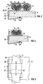
- 1, 2 show as a drive motor for a motor vehicle heater blower a commutator motor with a motor housing 5 with front bearing brackets 6; 7 and a rotor mounted therein with a rotor shaft end 10 protruding from the left bearing bracket 6, on a radial fan wheel in a manner not shown here is pushed open.
- feed lines to the two pivotable on the left bracket 6 hammer brush holders 8.9 serve two fixed on the outer circumference of the motor housing 5 feed lines, of which the negative line 3 with its right end via a terminal to the negative pole "-" a motor vehicle battery and with it left end to the input contact of a suppression choke 81 held on the back of the hammer brush holder 8 and with its output contact to the carbon brush of this hammer brush holder 8 and of which the positive line 4 with a clamp at its right free end to the positive pole "+” of the motor vehicle battery and with its left end to the input contact of a suppression choke 91 held on the back of the hammer brush holder 9 and connected with its output contact to the brush of this hammer brush holder.
- mounting clamps 2 and 2 which - as can be seen in particular in FIG. 3 - are double U-shaped or double V-shaped such that they have axially opened leg pairs 21; 22 or 23; 24 in the opposite direction, with the front edge part 51 of the motor housing 5 between the first leg pair 21; 22 and one or more feed lines being axially clampable between the second leg pair 23; 24.
- the mounting clamp 2 visible in FIG. 1 is pushed with its lower pair of legs axially onto the front edge part 51 and in their upper leg pair are first pressed in the positive line 4 and then the negative line 3. While the negative lead 3 is led directly to the input contact of the suppressor 81 after leaving the mounting clamp 2 visible in FIG. Bracket clamp 2 set and then leads to the input contact of the suppressor 91.
- a contact terminal 1 which by crimping with a back 13, encompasses the outer circumference of the insulation 31 of the negative line 3 and with tips 11, is used for the inventive electrical ground contact connection between the strand 32 of the negative line 3 and the motor housing 5 12 is pressed into the insulation 31 such that it contacts the inner strand 32 in an electrically conductive manner.
- FIG. 4,5 show, according to an embodiment of the invention, a further reduction possibility with regard to parts and assembly expenditure for establishing a contact connection in the form of a one-piece contact mounting clamp 1; 2, with the leg (22) of the bearing on the surface of the motor housing 5 first leg pair 21; 22 of the mounting clamp part a partially punched-out contact terminal part with the only recorded negative line 3 to be provided with a ground contact to the motor housing is crimped and pressed with its free tips 11; 12 on both sides of its back 13, which is partially integral with the mounting terminal part, through the insulation 31 until it comes into contact with the stranded wire 32 .
- the electrical contact connection according to the invention ensures a potential equalization between the negative line 3 and the motor housing 5 with little effort in terms of parts and assembly, with the components of an intermediate terminal board necessary in the known case, an additional stranded connection from the intermediate terminal board to the motor housing and on whose additional soldering on the intermediate terminal board or screw connection on the motor housing or on the bearing bracket can be dispensed with.
Landscapes
- Engineering & Computer Science (AREA)
- Power Engineering (AREA)
- Motor Or Generator Frames (AREA)
Description
- Die Erfindung bezieht sich auf eine Kontaktverbindung gemäß Oberbegriff des Anspruchs 1; eine derartige Kontaktverbindung ist durch eine offenkundige Vorbenutzung in Anwendung auf einen Kraftfahrzeug-Ventilatorantrieb bekannt.
- Im vorgenannten bekannten Fall werden als Speiseleitungen für den Antriebsmotor des Ventilators von der Kraftfahrzeug-Batterie je eine isolierte Minusleitung und eine isolierte Plusleitung zu einem am kommutatorseitigen Lagerbügel des Antriebsmotors als Leitungsstütze gehalterten Zwischenklemmbrett geführt; bei besonders langen Zuleitungen werden diese durch ein das Motorgehäuse mitumschlingendes Spannband zusätzlich lagefixiert. Von diesem Zwischenklemmbrett verlaufen neben je einer Verbindungsleitung für je einen der beiden Bürstenhalter von dem Minusleitungsanschluß eine mit ihrem einen Ende angelötete Kupferlitze, die über eine mit ihrem anderen Ende verbundene Öse mit einer Blechschraube elektrisch leitend mit einer Lagerbügelbohrung verschraubt ist. Die derart hergestellte Masseverbindung dient insbesondere dem zu einer vollkommenen Funkentstörung notwendigen Potentialausgleich zwischen der Masse der Kraftfahrzeug-Karosserie und den damit kontaktierten Bauteilen, wie z.B. dem Motorgehäuse des Antriebsmotors einerseits und der Minusleitung andererseits, deren batterieseitiger Anschlußpol eine Masseverbindung zu einem Kraftfahrzeug-Karosserieteil aufweist.
- Durch die DE-C2-29 36 290 ist ein Schutzleiteranschluß für Motore mit einem in eine stirnseitige Öffnung des Statorblechpaketes des Motors eingelegten und form- und/oder kraftschlüssig festgeklemmten Schutzleiteranschlußteil bekannt, bei dem die Öffnung als dicht unterhalb der äußeren Umfangsfläche des Statorblechpaketes verlaufende Einsteckbohrung für ein zuvor abisoliertes Ende des Schutzleiters ausgebildet und das eingesteckte, zuvor abisolierte Ende durch ein außen am Statorblechpaket über der Einsteckbohrung angesetztes Verstemmwerkzeug festklemmbar ist.
- Durch die US-A-3 435 126 ist ein Endanschluß für ein Erdkabel mit einer Vielzahl innerer Kupferleitungen, einem diese konzentrisch umgebenden Metallschild mit Korrosionsschutzüberzug und einem diesen wiederum konzentrisch umgebenden Isoliermantel bekannt, wobei zur Kontaktierung zwischen dem zum Freilegen der Kupferleitungsenden zurückgestülpten Metallschild und einem metallenen Kabelträger eine mit Krallen versehene Schelle mittels einer das Kabel an dem Kabelträger befestigten Kabelschelle derart an den Metallschild angedrückt wird, daß dessen außen liegender Korrosionsschutzüberzug durchstoßen wird.
- Durch die US-A-2 515 105 ist eine elektrische Steckverbindung bekannt, bei der Steckerlaschen dadurch mit elektrisch isolierten Leitungen kontaktiert sind, daß die Laschen ösenartig mit ihren steckerabgewandten Enden jeweils um eine Leitung gebogen sind und dabei aus der Laschenfläche vorstehende Zähne durch die Isolierung bis zu der Leitung durchdringen.
- Gemäß Aufgabe vorliegender Erfindung soll hinsichtlich Material- und Montageaufwand die Herstellung einer Masseverbindung zwischen dem Motorgehäuse des Antriebsmotors und einer Speiseleitung, vorzugsweise der Minusleitung, insbesondere unter Berücksichtigung einer Automatenfertigung, wesentlich vereinfacht werden.
- Die Lösung dieser Aufgabe gelingt bei einer elektrischen Kontaktverbindung der eingangs genannten Art durch die Lehre des Anspruchs 1; vorteilhafte Ausgestaltungen der Erfindung sind jeweils Gegenstand der Unteransprüche.
- Bei der erfindungsgemäßen Kontaktverbindung kann die zuvor mit einer die Isolation durchdringenden und mit der Litze elektrisch kontaktierenden Kontaktklemme versehene, durchgehend bis zum Bürstenhalter verlaufende Speiseleitung in eine zweckmäßigerweise gleichzeitig der Halterung am Motorgehäuse dienende und an diesem befestigte Halterungsklemme im Bereich der Kontaktklemme derart eingedrückt werden, daß ein Potentialausgleich von der Litze der Speiseleitung über die Kontaktklemme und die Halterungsklemme zum Motorgehäuse in einem Montagevorgang und unter Verzicht auf ein gesondertes Zwischenklemmbrett und eine gesonderte Masselitze und deren Verlötung und Verschraubung gewährleistet werden kann.
- Zweckmäßigerweise ist eine doppel-U-förmige bzw. doppel-V-förmige Halterungsklemme mit axial in entgegengesetzten Richtungen geöffneten Schenkelpaaren vorgesehen, zwischen deren erstem Schenkelpaar der eine stirnseitige Randteil des Motorgehäuses und zwischen deren zweitem Schenkelpaar die Kontaktklemme mit der elektrischen Leitung axial einklemmbar ist; dadurch ist in montagetechnisch besonders einfacher Weise in nur axialer Handhabungsrichtung sowohl die Halterungsklemme am Motorgehäuse befestigbar als auch die Speiseleitung mit der Kontaktklemme in die am Motorgehäuse befestigte Halterungsklemme eindrückbar.
- Die Erfindung sowie weitere vorteilhafte Ausgestaltungen der Erfindung gemäß Merkmalen der Unteransprüche werden im folgenden anhand schematisch dargestellter Ausführungsbeispiele in der Zeichnung näher erläutert; darin zeigen:
- FIG 1
- eine axiale Draufsicht auf einen Ventilator-Antriebsmotor;
- FIG 2
- eine Draufsicht auf die ventilatorradseitige Stirnseite des Antriebsmotors gemäß FIG 1;
- FIG 3
- einen Teilschnitt gemäß Schnittverlauf III-III in FIG 2;
- FIG 4
- einen Teilschnitt gemäß III-III in FIG 2, jedoch mit einer einteiligen Kontakt-Halterungsklemme;
- FIG 5
- die radiale Draufsicht auf die einteilige Kontakt-Halterungsklemme gemäß FIG 4.
- FIG 1, 2 zeigen als Antriebsmotor für ein Kraftfahrzeug-Heizungsgebläse einen Kommutatormotor mit einem Motorgehäuse 5 mit stirnseitigen Lagerbügeln 6;7 und darin gelagertem Rotor mit aus dem linken Lagerbügel 6 herausragendem Rotorwellenende 10, auf das in hier nicht näher dargestellter Weise ein Radialgebläse-Lüfterrad aufgedrückt wird. Als Speiseleitungen zu den beiden am linken Lagerbügel 6 schwenkbar gehaltenen Hammerbürstenhaltern 8,9 dienen zwei am Außenumfang des Motorgehäuses 5 festgelegte Speiseleitungen, von denen die Minusleitung 3 mit ihrem rechten Ende über eine Klemme an den Minuspol "-" einer Kraftfahrzeug-Batterie und mit ihrem linken Ende an den Eingangskontakt einer auf dem Rücken des Hammerbürstenhalters 8 gehaltenen und mit ihrem Ausgangskontakt an die Kohlebürste dieses Hammerbürstenhalters 8 führenden Entstördrossel 81 und von denen die Plusleitung 4 mit einer Klemme an ihrem rechten freien Ende an dem Pluspol "+" der Kraftfahrzeug-Batterie und mit ihrem linken Ende an den Eingangskontakt einer auf dem Rücken des Hammerbürstenhalters 9 gehaltenen und mit ihrem Ausgangskontakt an die Bürste dieses Hammerbürstenhalters angeschlossenen Entstördrossel 91 kontaktiert ist.
- Zur Halterung der Minusleitung 3 und der Plusleitung 4 am linken stirnseitigen Ende des Motorgehäuses 5 dienen Halterungsklemmen 2 bzw.2, die - wie insbes. aus FIG 3 ersichtlich - doppel-U-förmig bzw. doppel-V-förmig derart ausgebildet sind, daß sie axial in entgegengesetzter Richtung geöffnete Schenkelpaare 21;22 bzw. 23;24 aufweisen, wobei zwischen dem ersten Schenkelpaar 21;22 der stirnseitige Randteil 51 des Motorgehäuses 5 und zwischen dem zweiten Schenkelpaar 23;24 eine oder mehrere Speiseleitungen axial einklemmbar sind.
- Die in FIG 1 sichtbare Halterungsklemme 2 ist in montagetechnisch vorteilhafter Weise mit ihrem unteren Schenkelpaar axial auf den stirnseitigen Randteil 51 aufgeschoben und in ihr oberes Schenkelpaar sind zunächst die Plusleitung 4 und dann die Minusleitung 3 eingedrückt. Während die Minusleitung 3 nach Verlassen der in FIG 1 sichtbaren Halterungsklemme 2 direkt zum Eingangskontakt der Entstördrossel 81 geführt ist, verläuft die Plusleitung 4 tangential am Außenumfang des Motorgehäuses 5 bis zu dessen Rückseite, ist dort in eine weitere, insbes. aus FIG 2 ersichtliche, Halterungsklemme 2 festgelegt und führt dann zum Eingangskontakt der Entstördrossel 91.
- Wie insbes. aus FIG 3 ersichtlich, dient zur erfindungsgemäß besonders einfachen elektrischen Massekontaktverbindung zwischen der Litze 32 der Minusleitung 3 und dem Motorgehäuse 5 eine Kontaktklemme 1, die durch Crimpen mit einem Rücken 13 den Außenumfang der Isolation 31 der Minusleitung 3 umfaßt und mit Spitzen 11;12 derart in die Isolation 31 eingedrückt ist, daß diese elektrisch leitend die innere Litze 32 kontaktieren. Der die Isolation 31 außen umfassende Rücken 13 der Kontaktklemme 1 ist seinerseits zwischen den Schenkeln 23;24 der Halterungsklemme 2 derart eingedrückt, daß auch eine elektrische Massekontaktverbindung zwischen der Kontaktklemme 1 und der Halterungsklemme 2 gewährleistet ist; da die Halterungsklemme 2 mit ihrem ersten Schenkelpaar 21;22 auf den stirnseitigen Randteil 51 des Motorgehäuses 5 aufgedrückt und zusätzlich über einen Krallhaken 241 relativ zur Innenumfangsfläche des Motorgehäuses 5 lagefixiert ist, besteht auf einfache Weise eine sichere Massekontaktverbindung zwischen der Kontaktklemme 1 und dem Motorgehäuse 5.
- FIG 4,5 zeigen gemäß einer Ausgestaltung der Erfindung eine hinsichtlich Teile- als auch Montageaufwand noch weitere Reduzierungsmöglichkeit zur Herstellung einer Kontaktverbindung in Form einer einstückigen Kontakt-Halterungsklemme 1;2, wobei aus dem auf der Oberfläche des Motorgehäuses 5 aufliegenden Schenkel (22) des ersten Schenkelpaares 21;22 des Halterungsklemmenteils ein teilweise freigestanzter Kontaktklemmenteil mit der einzig aufgenommenen, mit einem Massekontakt zum Motorgehäuse zu versehenen Minusleitung 3 vercrimpbar abgebogen und mit seinen freien Spitzen 11;12 beidendseitig seines mit den Halterungsklemmenteils teilweise einstückigen Rückens 13 durch die Isolation 31 bis zum Kontakt mit der Litze 32 eingedrückt ist.
- Es ist ersichtlich, daß durch die erfindungsgemäße elektrische Kontaktverbindung mit geringem teile- und montagemäßigen Aufwand ein Potentialausgleich zwischen der Minusleitung 3 und dem Motorgehäuse 5 gewährleistet ist, wobei auf die im bekannten Fall notwendigen Bauteile eines Zwischenklemmbrettes, einer zusätzlichen Litzenverbindung vom Zwischenklemmbrett zum Motorgehäuse und auf deren zusätzliche Verlötung am Zwischenklemmbrett bzw. Verschraubung am Motorgehäuse oder am Lagerbügel verzichtet werden kann.
Claims (7)
- Kontaktverbindung zum Potentialausgleich für einen funkentstörten elektrischen Kraftfahrzeug-Motorhilfsantrieb zwichen einer von einer Isolation (31) umgebenden elektrischen Litze (32) einer Speiseleitung (Minus-Leitung 3) und einem diese halternden Motorstatorteil (Motorgehäuse 5), dadurch gekennzeichnet, daß die Speiseleitung (Minus-Leitung 3) in ihrem Verlauf entlang des Motorstatorteils (Motorgehäuse 5) an diesem durch eine Halterungsklemme (2) gehaltert und gleichzeitig über eine die Isolation (31) zumindest teilweise umfassende verformbare, durch die Isolation (31) bis zu der Litze (32) durchgedrückte und mit ihrer Außenfläche (Rücken 13) an den Motorstatorteil (Motorgehäuse 5) angedrückte Kontaktklemme (1) mit diesem elektrisch leitend verbunden ist.
- Kontaktverbindung nach Anspruch 1, dadurch gekennzeichnet, daß die Kontaktklemme (1) in eine an dem Motorgehäuse (5) elektrisch leitend befestigte Halterungsklemme (2) eingedrückt ist.
- Kontaktverbindung nach Anspruch 1 oder 2, gekennzeichnet durch eine doppel-U-förmige bzw. doppel-V-förmige Halterungsklemme (2) mit axial in entgegengesetzten Richtungen geöffneten Schenkelpaaren (21;22 bzw. 23;24), zwischen deren erstem Schenkelpaar (21;22) der eine stirnseitige Randteil (51) des Motorgehäuses (5) und zwischen deren zweitem Schenkelpaar (23;24) die Kontaktklemme (1) mit der Speiseleitung axial einklemmbar ist.
- Kontaktverbindung für einen aus einer Batterie mit einer Masseverbindung ihres einen Pols (Minuspol) über eine Minusleitung (3) sowie eine Plusleitung (4) gespeisten Elektro-Antriebsmotor, insbesondere Ventilator-Antriebsmotor, nach einem der Ansprüche 1-3, dadurch gekennzeichnet, daß die Kontaktklemme (1) auf die Minusleitung (3) gepreßt und an der kommutatorseitigen Stirnseite (Randteil 51) des Motorgehäuses (5) über die Halterungsklemme (2) befestigt und mit dem Motorgehäuse (5) kontaktiert ist.
- Kontaktverbindung nach einem der Ansprüche 1 - 4, gekennzeichnet durch eine Kontaktklemme (1) in Clip-Form mit beidendseitig ihres Rückens (13) beim Vercrimpen um die Speiseleitung (Minusleitung 3) durch deren Isolation (31) bis zu deren Litze (32) durchdrückbaren Spitzen (11;12).
- Kontaktverbindung nach einem der Ansprüche 1 - 5, gekennzeichnet durch eine Halterungsklemme (2) mit zumindest einem an dem Motorgehäuse (5), vorzugsweise an dessen Innenumfangsfläche, fixierbarem Krallhaken (211) an zumindest einem Schenkel (21) des ersten Schenkelpaares (21;22).
- Kontaktverbindung nach einem der Ansprüche 1 - 6, gekennzeichnet durch eine einstückige Kontakt-Halterungskemme (1,2) mit aus dem auf der Oberfläche des Motorgehäuses (5) aufliegenden Schenkel (22) des ersten Schenkelpaares (21;22) des Halterungsklemmenteils teilweise freigestanzten und als Clip mit der Speiseleitung (Minusleitung 3) vercrimpbaren Kontaktklemmenteil.
Priority Applications (3)
| Application Number | Priority Date | Filing Date | Title |
|---|---|---|---|
| DE59102947T DE59102947D1 (de) | 1991-03-22 | 1991-03-22 | Elektrische Kontaktverbindung. |
| EP91104575A EP0504469B1 (de) | 1991-03-22 | 1991-03-22 | Elektrische Kontaktverbindung |
| DE9203422U DE9203422U1 (de) | 1991-03-22 | 1992-03-13 | Kontaktverbindung |
Applications Claiming Priority (1)
| Application Number | Priority Date | Filing Date | Title |
|---|---|---|---|
| EP91104575A EP0504469B1 (de) | 1991-03-22 | 1991-03-22 | Elektrische Kontaktverbindung |
Publications (2)
| Publication Number | Publication Date |
|---|---|
| EP0504469A1 EP0504469A1 (de) | 1992-09-23 |
| EP0504469B1 true EP0504469B1 (de) | 1994-09-14 |
Family
ID=8206564
Family Applications (1)
| Application Number | Title | Priority Date | Filing Date |
|---|---|---|---|
| EP91104575A Expired - Lifetime EP0504469B1 (de) | 1991-03-22 | 1991-03-22 | Elektrische Kontaktverbindung |
Country Status (2)
| Country | Link |
|---|---|
| EP (1) | EP0504469B1 (de) |
| DE (2) | DE59102947D1 (de) |
Cited By (2)
| Publication number | Priority date | Publication date | Assignee | Title |
|---|---|---|---|---|
| WO2007093544A1 (de) | 2006-02-17 | 2007-08-23 | Brose Fahrzeugteile Gmbh & Co. Kg | Funkentstörte antriebseinheit, insbesondere zum antrieb eines kraftfahrzeuggebläses |
| US10181658B2 (en) | 2016-03-31 | 2019-01-15 | Borgwarner Inc. | Electric machine with electrical connector |
Families Citing this family (9)
| Publication number | Priority date | Publication date | Assignee | Title |
|---|---|---|---|---|
| FR2694141B1 (fr) * | 1992-07-23 | 1994-08-19 | Cit Alcatel | Agrafe auto-dénudante de mise à la masse d'un câble. |
| FR2711282B1 (fr) * | 1993-10-13 | 1995-11-24 | Valeo Equip Electr Moteur | Machine tournante électrique, notamment alternateur de véhicule automobile comportant un dispositif de retenue de câble. |
| US6276947B1 (en) * | 1999-08-04 | 2001-08-21 | Illinois Tool Works | U-crimp |
| ES2228892T3 (es) * | 2000-05-22 | 2005-04-16 | Siemens Aktiengesellschaft | Procedimiento para motor electrico, en particular motor de conmutador. |
| DE10260284A1 (de) * | 2002-12-20 | 2004-07-15 | Siemens Ag | Elektrische Maschine |
| DE102006026477A1 (de) * | 2006-06-07 | 2007-12-13 | Siemens Ag | Massekontaktelement |
| JP4915707B2 (ja) * | 2009-11-27 | 2012-04-11 | 関東自動車工業株式会社 | クランプ |
| DE102011088537A1 (de) * | 2011-12-14 | 2013-06-20 | Metabowerke Gmbh | Verfahren zum Herstellen eines Stators sowie Stator |
| FR3036857B1 (fr) | 2015-06-01 | 2017-07-07 | A Raymond Et Cie | Clip metallique de connexion electrique d'un fil conducteur a un element metallique |
Family Cites Families (6)
| Publication number | Priority date | Publication date | Assignee | Title |
|---|---|---|---|---|
| US2515105A (en) * | 1947-08-08 | 1950-07-11 | Allied Electric Products Inc | Method of making an electrical connection to an insulated wire |
| US3021581A (en) * | 1958-11-12 | 1962-02-20 | Steel City Electric Company | Ground clip for electrical outlet and switch boxes |
| NL148197B (nl) * | 1972-05-16 | 1975-12-15 | Amp Inc | Elektrisch verbindingsorgaan voor het aansluiten aan een einde van een coaxiale kabel met twee evenwijdig gelegen contactorganen en waarbij twee krimpbuisorganen aanwezig zijn. |
| US3435126A (en) * | 1967-01-04 | 1969-03-25 | Douglas L P Hamilton | Means securing a cable sheath to a grounding and supporting member |
| US3551713A (en) * | 1967-10-23 | 1970-12-29 | Franklin A White | Motor hook-up ring |
| DE2936290C2 (de) * | 1979-09-07 | 1986-11-13 | Siemens Ag, 1000 Berlin Und 8000 Muenchen | Schutzleiteranschluß für Motoren, insbesondere Außenläufer-Kleinmotoren, und Verfahren zur Herstellung des Schutzleiteranschlusses |
-
1991
- 1991-03-22 EP EP91104575A patent/EP0504469B1/de not_active Expired - Lifetime
- 1991-03-22 DE DE59102947T patent/DE59102947D1/de not_active Expired - Fee Related
-
1992
- 1992-03-13 DE DE9203422U patent/DE9203422U1/de not_active Expired - Lifetime
Cited By (2)
| Publication number | Priority date | Publication date | Assignee | Title |
|---|---|---|---|---|
| WO2007093544A1 (de) | 2006-02-17 | 2007-08-23 | Brose Fahrzeugteile Gmbh & Co. Kg | Funkentstörte antriebseinheit, insbesondere zum antrieb eines kraftfahrzeuggebläses |
| US10181658B2 (en) | 2016-03-31 | 2019-01-15 | Borgwarner Inc. | Electric machine with electrical connector |
Also Published As
| Publication number | Publication date |
|---|---|
| DE9203422U1 (de) | 1992-05-27 |
| DE59102947D1 (de) | 1994-10-20 |
| EP0504469A1 (de) | 1992-09-23 |
Similar Documents
| Publication | Publication Date | Title |
|---|---|---|
| DE69206865T2 (de) | Miniaturmotor | |
| DE102009038258A1 (de) | Bürstenträger eines Motors | |
| EP0504469B1 (de) | Elektrische Kontaktverbindung | |
| EP3928419B1 (de) | Antriebsvorrichtung mit einem bürstenlosen elektromotor | |
| WO2015007836A1 (de) | Vorrichtung zur elektrischen kontaktierung einer abschirmung eines elektrischen kabels | |
| DE19748150B4 (de) | Spindelmotor mit Kontaktierung | |
| DE102009038144A1 (de) | Elektromotor | |
| DE60104575T2 (de) | Bürstenhalteranordnung | |
| DE3417266A1 (de) | Gleichstrommotor, insbesondere elektrische kraftstoffoerderpumpe fuer kraftfahrzeuge | |
| DE102018221859B4 (de) | Kommutatormotor und Baureihe von Kommutatormotoren | |
| DE3314412C2 (de) | ||
| DE3604583C2 (de) | ||
| DE102018200195B4 (de) | Antrieb mit einem kommutatormotor | |
| DE102010044872B4 (de) | Anschlussdose für Solarmodul | |
| EP0384131B1 (de) | Elektro-Aussenläufermotor mit Schutzleiter-Anschlussteil | |
| DE19705833A1 (de) | Bürstenhalteanordnung | |
| DE102016221677A1 (de) | Elektrischer Rotor mit Verbindungsanordnung | |
| CH673917A5 (de) | ||
| EP0174578B1 (de) | Gerätestecker mit nachgeschaltetem elektrischen Entstörfilter | |
| EP1792382B1 (de) | Gleichstrommotor mit entstörvorrichtung | |
| DE4323065A1 (de) | Elektromotor, insbesondere Kommutatormotor mit einem Ständerblechpaket | |
| EP1285485B1 (de) | Elektromotor, insbesondere kommutatormotor | |
| EP0201035B1 (de) | Koaxialkabelanschluss an einer Federleiste | |
| DE3434429A1 (de) | Entstoerter kommutator-motor | |
| DE3538942A1 (de) | Feldstecker fuer einen elektromotor |
Legal Events
| Date | Code | Title | Description |
|---|---|---|---|
| PUAI | Public reference made under article 153(3) epc to a published international application that has entered the european phase |
Free format text: ORIGINAL CODE: 0009012 |
|
| 17P | Request for examination filed |
Effective date: 19920325 |
|
| AK | Designated contracting states |
Kind code of ref document: A1 Designated state(s): DE FR GB IT |
|
| 17Q | First examination report despatched |
Effective date: 19940121 |
|
| GRAA | (expected) grant |
Free format text: ORIGINAL CODE: 0009210 |
|
| AK | Designated contracting states |
Kind code of ref document: B1 Designated state(s): DE FR GB IT |
|
| REF | Corresponds to: |
Ref document number: 59102947 Country of ref document: DE Date of ref document: 19941020 |
|
| ITF | It: translation for a ep patent filed | ||
| GBT | Gb: translation of ep patent filed (gb section 77(6)(a)/1977) |
Effective date: 19941110 |
|
| ET | Fr: translation filed | ||
| PLBE | No opposition filed within time limit |
Free format text: ORIGINAL CODE: 0009261 |
|
| STAA | Information on the status of an ep patent application or granted ep patent |
Free format text: STATUS: NO OPPOSITION FILED WITHIN TIME LIMIT |
|
| 26N | No opposition filed | ||
| PGFP | Annual fee paid to national office [announced via postgrant information from national office to epo] |
Ref country code: GB Payment date: 19970224 Year of fee payment: 7 |
|
| PG25 | Lapsed in a contracting state [announced via postgrant information from national office to epo] |
Ref country code: GB Free format text: LAPSE BECAUSE OF NON-PAYMENT OF DUE FEES Effective date: 19980322 |
|
| GBPC | Gb: european patent ceased through non-payment of renewal fee |
Effective date: 19980322 |
|
| PGFP | Annual fee paid to national office [announced via postgrant information from national office to epo] |
Ref country code: IT Payment date: 20090321 Year of fee payment: 19 Ref country code: DE Payment date: 20090331 Year of fee payment: 19 |
|
| PGFP | Annual fee paid to national office [announced via postgrant information from national office to epo] |
Ref country code: FR Payment date: 20090316 Year of fee payment: 19 |
|
| REG | Reference to a national code |
Ref country code: FR Ref legal event code: ST Effective date: 20101130 |
|
| PG25 | Lapsed in a contracting state [announced via postgrant information from national office to epo] |
Ref country code: FR Free format text: LAPSE BECAUSE OF NON-PAYMENT OF DUE FEES Effective date: 20100331 |
|
| PG25 | Lapsed in a contracting state [announced via postgrant information from national office to epo] |
Ref country code: DE Free format text: LAPSE BECAUSE OF NON-PAYMENT OF DUE FEES Effective date: 20101001 |
|
| PG25 | Lapsed in a contracting state [announced via postgrant information from national office to epo] |
Ref country code: IT Free format text: LAPSE BECAUSE OF NON-PAYMENT OF DUE FEES Effective date: 20100322 |