EP0504164B1 - Hauptzylinder mit geschichteten kommunikationsanschlüssen - Google Patents
Hauptzylinder mit geschichteten kommunikationsanschlüssen Download PDFInfo
- Publication number
- EP0504164B1 EP0504164B1 EP90916892A EP90916892A EP0504164B1 EP 0504164 B1 EP0504164 B1 EP 0504164B1 EP 90916892 A EP90916892 A EP 90916892A EP 90916892 A EP90916892 A EP 90916892A EP 0504164 B1 EP0504164 B1 EP 0504164B1
- Authority
- EP
- European Patent Office
- Prior art keywords
- master cylinder
- housing part
- interface
- opening
- accordance
- Prior art date
- Legal status (The legal status is an assumption and is not a legal conclusion. Google has not performed a legal analysis and makes no representation as to the accuracy of the status listed.)
- Expired - Lifetime
Links
Images


Classifications
-
- B—PERFORMING OPERATIONS; TRANSPORTING
- B60—VEHICLES IN GENERAL
- B60T—VEHICLE BRAKE CONTROL SYSTEMS OR PARTS THEREOF; BRAKE CONTROL SYSTEMS OR PARTS THEREOF, IN GENERAL; ARRANGEMENT OF BRAKING ELEMENTS ON VEHICLES IN GENERAL; PORTABLE DEVICES FOR PREVENTING UNWANTED MOVEMENT OF VEHICLES; VEHICLE MODIFICATIONS TO FACILITATE COOLING OF BRAKES
- B60T11/00—Transmitting braking action from initiating means to ultimate brake actuator without power assistance or drive or where such assistance or drive is irrelevant
- B60T11/10—Transmitting braking action from initiating means to ultimate brake actuator without power assistance or drive or where such assistance or drive is irrelevant transmitting by fluid means, e.g. hydraulic
- B60T11/16—Master control, e.g. master cylinders
-
- B—PERFORMING OPERATIONS; TRANSPORTING
- B60—VEHICLES IN GENERAL
- B60T—VEHICLE BRAKE CONTROL SYSTEMS OR PARTS THEREOF; BRAKE CONTROL SYSTEMS OR PARTS THEREOF, IN GENERAL; ARRANGEMENT OF BRAKING ELEMENTS ON VEHICLES IN GENERAL; PORTABLE DEVICES FOR PREVENTING UNWANTED MOVEMENT OF VEHICLES; VEHICLE MODIFICATIONS TO FACILITATE COOLING OF BRAKES
- B60T11/00—Transmitting braking action from initiating means to ultimate brake actuator without power assistance or drive or where such assistance or drive is irrelevant
- B60T11/10—Transmitting braking action from initiating means to ultimate brake actuator without power assistance or drive or where such assistance or drive is irrelevant transmitting by fluid means, e.g. hydraulic
- B60T11/16—Master control, e.g. master cylinders
- B60T11/20—Tandem, side-by-side, or other multiple master cylinder units
-
- B—PERFORMING OPERATIONS; TRANSPORTING
- B60—VEHICLES IN GENERAL
- B60T—VEHICLE BRAKE CONTROL SYSTEMS OR PARTS THEREOF; BRAKE CONTROL SYSTEMS OR PARTS THEREOF, IN GENERAL; ARRANGEMENT OF BRAKING ELEMENTS ON VEHICLES IN GENERAL; PORTABLE DEVICES FOR PREVENTING UNWANTED MOVEMENT OF VEHICLES; VEHICLE MODIFICATIONS TO FACILITATE COOLING OF BRAKES
- B60T11/00—Transmitting braking action from initiating means to ultimate brake actuator without power assistance or drive or where such assistance or drive is irrelevant
- B60T11/10—Transmitting braking action from initiating means to ultimate brake actuator without power assistance or drive or where such assistance or drive is irrelevant transmitting by fluid means, e.g. hydraulic
- B60T11/16—Master control, e.g. master cylinders
- B60T11/22—Master control, e.g. master cylinders characterised by being integral with reservoir
Definitions
- the present invention relates generally to a master cylinder, and in particular to a master cylinder having a pair of interface members sandwiched between two housing parts connected together.
- the invention concerns a type of master cylinder known generally as a recessed cartridge master cylinder and disclosed in U. S. Patent No. 4,718,234.
- the master cylinder includes two die cast components one of which is threaded into the other, and a sleeve member located in the one part.
- the assembly of the two die cast components is sensitive to assembly torque.
- the assembly torque effects directly the master cylinder function due to the compression set of the plastic components which could possibly close off the pumping flow ports even though they were open during production testing.
- the male/female threads of the two die cast components have very tight tolerances which are required in order to orient the internal components with respect to concentricity. During assembly, several individual seal components must be oriented during assembly.
- the assembly and function of the seals is sensitive to diametric fit, roundness, and concentricity of several components.
- the outlet ports extend to the side and this dictates the location and orientation of a fluid level indicator within the reservoir in addition to the shape of the reservoir in order to permit access for tools which receive the brake line tube nuts.
- the reservoir is typically held to the housing by means of a wire retainer. Because of the shape of the die cast housing, the die utilized results in a limited number of cavities. These can be difficult to maintain since the diameters are large. It is highly desirable to eliminate or improve a large number of the above problems while still providing a very short recessed cartridge type of master cylinder which provides a significant reduction in packaging space under the hood of an automotive vehicle. Such packaging space has become important with the advent of adaptive braking control systems which can require considerable space within the vehicle motor area.
- a master cylinder comprising a first housing part and a second housing part and having an end of one part received at the end of the other part so that the parts define therebetween an interior opening comprising a bore, a sleeve member received within said second housing part, first piston means slideably received within an end opening of said second housing part, second piston means received within said bore and biased by first resilient means, second resilient means disposed between said pistons, and a reservoir communicating with said bore, characterized in that first and second interface members are captured between said first and second housing parts and the interface members have sealing members molded thereupon to provide fluid flow paths between the reservoir and bore and between said bore and fluid outlets.
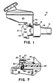
- the master cylinder of the present invention is designated generally by reference numeral 10 in Figure 1.
- Master cylinder 10 includes a first or front housing part 12 and a second or rear housing part 14.
- Housing part 14 has an end opening 16 receiving therein first piston means 18.
- First piston means 18 is biased by a resilient assembly 20 (see Figure 6) located between first piston means 18 and second piston means 22.
- Second piston means 22 is biased by a resilient assembly 24.
- the housing parts 12 and 14 define an interior opening which comprises a master cylinder bore 26.
- the second housing part includes a sleeve member 28 which permits fluid flow between the sleeve member and second housing part 14 to the primary pressure chamber 30.
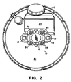
- the primary pressure chamber 30 transmits fluid pressure to primary outlet ports 36 (see Figure 2).
- the secondary pressure chamber 32 transmits fluid pressure to secondary outlet ports 34.
- a reservoir 40 includes secondary and primary reservoir ports 141 and 142, respectively, which are received at receiving ports of a second interface member.
- the master cylinder includes a wall member 50 ( Figure 1) which may be attached separately to master cylinder 10, or comprise a firewall, or comprise the wall of a booster device. The wall member 50 engages the rear wall 43 of reservoir 40 so that reservoir 40 is captured between wall member 50 and first housing part 12.
- master cylinder 10 is shown attached to a vacuum brake booster 60.
- the primary and secondary outlet ports 36, 34 are all oriented longitudinally toward the front of the master cylinder so that the brake line tube nuts are easily coupled therewith.
- the first housing part 12 includes flanges 13 having openings 15 which receive therein screw and nut mechanisms 17. The screw and nut mechanisms engage the front shell or wall member 51 of vacuum brake booster 60 in order to attach thereto master cylinder 10.
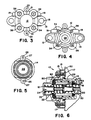
- Figure 3 illustrates a front end view of the first housing part 12 of the master cylinder illustrated generally in Figures 1 and 2.
- Housing part 12 includes radially extending wall sections 19 which, in conjunction with any type of rear wall means as disclosed above, assists in capturing and holding the reservoir in position.
- Radial wall extensions 21 include non-threaded openings 23 which will be described in detail below.
- the primary outlet ports 36 are threaded as are secondary outlet ports 34. Referring to Figure 4, the reverse side or interior side of first housing part 12 is illustrated.
- FIG. 5 illustrates the interior of second housing part 14 which is generally concentric with first housing part 12 and includes therein a portion of bore 26. Housing flanges 27 include non-threaded openings 25 which will be discussed in detail below.
- Figure 6 is a section view of the entire master cylinder shown attached to a wall member 50. Subsequent section views have deleted the resilient assemblies 20 and 24 in order to make the drawings more clearly understandable.
- wall member 50 may comprise a separate wall member, firewall, or the front wall of a booster housing.
- First housing part 12 is generally "U" shaped and receives therein second housing part 14.
- Second housing part 14 includes the sleeve member 28 which has at one end a primary land 70 with sealing members 72 insert molded thereon.
- Second housing part 14 includes the rear opening 16 which receives slideably the primary piston 18.
- a sealing member 72 engages the primary piston 18 in order to retain fluid within the primary chamber 30.
- the seal and primary land assembly are constructed essentially the same as in prior recessed cartridge master cylinders, with the exception that the seals are insert-molded onto the land member rather than being separate components. However, the rear seal 72A may be alternatively manufactured separately from land 70 and seals 72.
- the secondary piston 22 defines with housing first part 12 a secondary pressure chamber 32. Secondary piston 22 at one end engages seals which are mounted upon first interface member 80 and second interface member 90. The interface members 80, 90 are sandwiched or captured between the first and second housing parts and between the first housing part and sleeve member 28.
- first and second housing parts 12 and 14 are assembled together with all of the other inte- rior components of the master cylinder located therein, the housing parts are held together by means of self-threading screws 100 which are illustrated in Figure 7. Self-threading screws 100 are received within unthreaded openings 23 and 25 of extensions 21 and 27.
- a clamp load is maintained by a holding fixture and the self-threading screws 100 inserted within the openings 23 and 25 so that the second and first housing parts are held together at a fixed clamp load.
- the interfaces 80 and 90 are captured or sandwiched between the first and second housing parts as shown in Figure 7.
- First interface member 80 comprises a plastic member which has resilient sealing members insert molded thereupon.
- Member 80 includes an interior opening 81 bounded by seal 81A which defines a portion of bore 26.
- Flanges 82 include openings 83 for the self-threading screws 100.
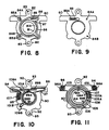
- Figure 8 is a front view of interface member 80, as viewed when looking at the front of the master cylinder illustrated in Figures 2 and 3. Comparing Figures 8 and 3, it can be seen that interface openings 84A, 84B are located within seal members 85A, 85B for the primary outlets 36.
- the seal member 86 provides an enclosed flow path area 87 oriented with the secondary outlets 34.
- Seal member 86 includes a recessed interior seal pad 88 which includes a slot opening 89.
- Slot opening 89 permits fluid flow between the front and rear sides of interface member 80.
- Figure 9 illustrates the reverse or back side of interface member 80.
- the openings 84A, 84B for the primary outlet ports 36 are shown.
- Interface member 80 includes a longitudinal opening 89A which exposes the slot opening 89. Longitudinal opening 89A will permit a protruding portion 89B of the second interface member 90 to extend into opening 89A and engage the perimeter of slot opening 89 to provide a secondary pumping zone for the secondary pressure chamber 32.
- the second interface member 90 is illustrated in a front view in Figure 10 which corresponds to the front views of Figures 2 and 3, and a rear or reverse view of interface member 90 is Figure 11. It should be noted that the interfaces 80 and 90 abut each other when they are captured or sandwiched between the housing parts 12 and 14. Thus, Figures 8 and 10 provide front views of the two interface members, and Figures 9 and 11 provide reverse or rear views of the two interface members.
- Figure 10 illustrates second interface member 90 which provides an interior opening 91 that defines a portion of bore 26. Extensions 92 provide openings 93 for the self-threading screws 100.
- Interface opening 94 provides an inlet opening for a primary inlet port 142 ( Figure 14) of the reservoir 40.
- Seal member 95 provides a sealed pathway so that fluid can flow from the primary inlet port to the primary chamber 30 of master cylinder 10.
- opening 96 permits fluid to flow from a secondary reservoir inlet port 141 ( Figure 12) to secondary pressure chamber 32 via a seal member 97 which provides a sealed pathway.
- Member 90 includes an axially extending abutment 89B which, when compared with Figure 8, can be seen to extend through the opening 89A of first interface member 80 and engage the slot opening 89.
- Second interface member 90 includes primary outlet openings 99A and 99B which communicate with the seals 101A and 101B in order to permit fluid to flow to the primary outlet ports 36 illustrated in Figure 3.
- the seals 101A and 101B provide sealing pathways for fluid flow to the respective outlet ports.
- Figure 11 shows the reverse or back side of second interface member 90 wherein a seal member 102 within interface receiving port 94A is provided adjacent opening 94 so that fluid may flow from the primary inlet port 142 of the reservoir 40.
- Seal member 103 within interface receiving port 96A provides a sealed pathway to opening 96 so that fluid may be communicated from the reservoir 40 via the secondary inlet port 141.
- the seal members 105 and 106 have respective thinned areas 105A and 106A, area 106A being part of the primary pumping zone for primary pressure chamber 30 of the master cylinder. Thinned area 105A provides a flow path between sleeve extension 28A ( Figure 15) and the seal 105.
- Area 105A is adjacent the through opening 107 in member 90. Adjacent opening 107 is relieved area 107A which permits pumping fluid flow.
- Inner diameter seal 91A engages secondary piston 22 and the inside edge of the seal extends radially slightly past the edge of opening 91 as can be seen in Figure 15.
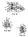
- Figure 12 there is illustrated in section view the secondary reservoir inlet port 141 and its communication with the second pressure chamber 32 of master cylinder 10, and Figure 12A is an enlarged partial section view of the compensation path.
- Figure 13 comprises an enlarged partial section view of Figure 12.
- First interface member 80 abuts in part second interface member 90.
- Second interface member 90 includes the seal 103 at inlet opening 96 and which is disposed about secondary reservoir inlet port 141 to effect sealing therebetween.
- First interface member 80 includes the interior seal 81A which engages the end of secondary piston 22 to define a portion of the secondary pressure chamber 32.
- the compensation flow path is from reservoir inlet port 141 through opening 96, and along a flow way bounded by seal 97 to communicate directly with the secondary chamber 32 by means of the piston groove 22A.
- Seal 86 defines a part of the pumping flow path between the secondary reservoir inlet port 141 and secondary pressure chamber 32.
- the seal pad 88 (see Figures 8 and 13) includes the slot opening 89 which is part of the flow path.
- Second interface member 90 includes the axial abutment or protrusion 89B ( Figure 10) which extends through the longitudinal opening 89A of first interface member 80 to seal selectively the slot opening 89.
- the longitudinal abutment 89B engages the perimeter of opening 89 of seal pad 88 such that pumping fluid flow may be provided between reservoir 40 ( Figure 12) and secondary chamber 32 as shown by the arrows, when the secondary piston 22 is returning toward an at rest position.
- pumping fluid flow may be provided between reservoir 40 ( Figure 12) and secondary chamber 32 as shown by the arrows, when the secondary piston 22 is returning toward an at rest position.
- reverse flow is not permitted because during operation of the master cylinder the higher pressure in secondary chamber 32 will force the perimeter of seal pad 88 against the abutment 93 to close off the fluid flow path to the reservoir.
- FIGS 14 and 15 illustrate in detail the communication path for the primary reservoir port.
- Reservoir 40 includes a primary reservoir port 142 which engages sealingly the seal 102 of second interface member 90. Fluid may flow between port 142 and inlet opening 94 of second interface 90.
- a flow path 143 exists between interface members 80 and 90.
- Second interface member 90 includes the circumferential opening 107 which permits fluid to flow from path 143 to compensation longitudinal flow path 29 between second housing part 14 and sleeve member 28. Circumferential opening 107 is located between the thinned seal areas 105A and 106A.
- the sleeve 28 includes a sleeve end extension 28A which is received between seal areas 105A, 106A.
- fluid may flow from primary inlet port 142 through opening 94 in second interface member 90, through flow path 143 and back through second interface member 90 by means of opening 107 which communicates with the longitudinal pathway 29.
- the closing off of compensation longitudinal flow path 29 is effected by the end of piston 18 moving past the seals 72 and land 70 adjacent opening 16 of second housing part 14.
- the seal 106 comprises a moveable seal member which, when pressure within primary pressure chamber 30 increases, permits thinned seal area 106A to tightly engage the sleeve extension 28A ( Figure 15) and prevent fluid flow into pathway 143 and reservoir 40.
- Figure 16 illustrates a section view of the flow path to a primary outlet port 36.
- First interface member 80 includes the primary outlet openings 84A, 84B (see Figure 8) enclosed by the seals 85A, 85B, respectively.
- Second interface member 90 includes the seal 101A (see Figure 10) which communicates with the primary outlet opening 99A, and seal 101B which communicates with primary outlet opening 99B.
- the opposite side of second interface member 90 includes the seals 91A, 106 and 105. Located between seals 91A and 106 is the primary outlet flow path 108 on second interface member 90.
- Path 108 communicates the primary pressure chamber 30 of master cylinder 10 with outlet openings 99A, 99B, thereby providing fluid flow paths via pathways 109B (see Figure 10) to primary outlet ports 36.
- the flow path is from primary pressure chamber 30 to path 108, through openings 99A, 99B, along pathways 109A, 109B, and through openings 84A, 84B to the areas bounded by seals 85A, 85B and to ports 36.
- Figures 17 and 18 illustrate the assembly of the first interface member 80 and the first housing part 12 at a primary outlet port 36.
- the seals 81A, 86 and 85A are insert molded on first interface member 80 when it is manufactured.
- first interface member 80 is coupled with first housing part 12 so that opening 84A in member 80 provides a communication flow path via the arrow illustrated in Figure 18.
- Figures 19 and 20 illustrate the assembly of the first interface member 80 with first housing part 12 to provide a flow path to a secondary outlet port 34.
- First interface member 80 includes the seal 86 and seal 81A which engage first housing part 11 as illustrated in Figure 20 so that a flow path via the arrow is provided between the secondary pressure chamber 32 and a secondary outlet port 34.
- master cylinder 10 provides fluid flow paths by means of the first and second interface members 80 and 90 which are layers of plastic and provide appropriate interfacing between the housing parts.
- the housing parts 12 and 14 are connected together, sandwiching the interface members in between, via the self-threading screws 100. All of the sealing within the master cylinder is accomplished via the insert molding of seals onto the interface members 80, 90 and rear land 70. This provides the major advantages of the elimination of parts and preventing the occurrence of mis-assembling parts.
- the master cylinder would be held in an assembled configuration by means of a clamping fixture that holds the interface members together so that they are sandwiched along with the sleeve and primary land member between the first and second housing parts.
- the clamp load upon the housing parts may be toleranced to provide a load that was previously supplied by torquing the threaded end cap into the threaded housing of the master cylinder.
- the clamp load via the fixture can be controlled to a much tighter tolerance because the thread friction between the previous end cap and threaded housing is eliminated.
- the self-threading screws are screwed into the associated housing openings to fix the housing parts together.
- the screws are self-taping which results in a locking of the two housings at the clamp load set by the fixture.
- the screws may have coarse thread size to accommodate misalignment of the die-cast holes.
- the interface members 80 and 90 are the means which provide the communication paths to the reservoir ports and outlet ports.
- the outlet ports in the first housing part are directed forwardly so that the communication hole of each outlet port is cast with only flash that separated the two halves of the die having to be removed during the trimming operation.
- Virtually all of the seal fits are designed with interference in the axial direction, thereby utilizing the significantly smaller nominal dimensions and smaller tolerances which are not present with the conventional diametric dimensioning. This also eliminates the detrimental effects of an out-of-round and eccentric condition that is critical to the previous design.
- the reservoir ports are incorporated into the second interface member 90 and are directed horizontally toward the rear wall member 50.
- the reservoir is trapped in position between the interface members and front housing part on one side and the wall member on the other side when the master cylinder is assembled to a vacuum booster.
- the pumping function of a combined pumping and pressurization function of the master cylinder is separated from the previous location at the rear land member and is now located at the interface member region.
- the master cylinder of the present invention provides the above advantages in addition to eliminating the previous side porting orientation for the outlet ports which required a very narrow master cylinder in order to allow access for the tools of the brake line tube nuts.
- the front oriented outlet ports also enable an improved location and orientation of a fluid level indicator, in addition to the elimination of a wire retainer for holding the reservoir to the master cylinder housing.
- the die-cast housing assembly procedure is improved so that the casting operation is improved and a larger number of cavities may be provided.
- the previously used seals are sensitive to diametric fit, roundness, and concentricity of several components. These parameters tend to be difficult to hold since the diameters are large. This is also eliminated.
- the present invention can eliminate or provide the following which is utilized in prior recessed cartridge master cylinder constructions: 1. The drilling of communications holes for the communication of reservoir and outlet ports; 2. Reaming and tapping of large diameter threads which attach the front and rear housing parts; 3. The sensitivity to torque when assembling the first housing part to the second housing part; 4. The assembly of all seals since all the seals in the present master cylinder are insert molded to the interface members 80, 90 and the primary land 70; 5. The sensitivity of the seals to roundness of the sleeve for sealing; 6. The sensitivity of the seals to misassembly due to "fold-over" when the pumping seals enter the sleeve or housing; 7.
- the wire retainer for the reservoir due to the horizontal orientation of the reservoir ports and the reservoir's entrapment between the master cylinder port and the wall member; 8.
- Multi-directional pulls for the die-cast housing which limited the die to four cavities; the present invention providing for the use of unidirectional die motion, thereby permitting a higher number of cavities, and improved dimensional control and lower cost; 11. All machining operations on the second housing part; 12. Access and fit problems for assembly of brake lines because all of the outlet ports are now readily accessible at the front of the master cylinder; 13.
- the reservoir packaging via expandability of the reservoir by several inches to the outboard side of the housing due to the relocation of the outlet ports; 14.
- the sealability of the pistons via the complete separation of the seal to the piston from the seal to the housing (secondary seal) or the seal to the sleeve (primary seal), i.e. the inner and outer seals function independently; 15.
- Machining operations reduced just to the first housing part in order to tap the threads for the outlet ports; 18. All seals automatically oriented via insert molding; and 19.
- the assembly can be completely tested in the clamped position to detect any defects so that proper corrective action can be taken prior to fixing together the components.
- the master cylinder of the present invention provides a significant step forward in the ease of assembly, manufacturing, and reduction of manufacturing costs for a recessed cartridge type of master cylinder.
Landscapes
- Engineering & Computer Science (AREA)
- Transportation (AREA)
- Mechanical Engineering (AREA)
- Transmission Of Braking Force In Braking Systems (AREA)
- Near-Field Transmission Systems (AREA)
- Sewage (AREA)
- Actuator (AREA)
- Management, Administration, Business Operations System, And Electronic Commerce (AREA)
Claims (10)
- Hauptzylinder (10) mit einem ersten Gehäuseteil (12) und einem zweiten Gehäuseteil (14), wobei ein Ende des einen Teils (12) am Ende des anderen Teils (14) aufgenommen ist, so daß die Teile (12,14) zwischen sich eine innere Öffnung (26) bilden, mit einer Bohrung (26), einer in dem zweiten Gehäuseteil (14) aufgenommenen Hülse (28), einem ersten in einer endseitigen Öffnung (16) des zweiten Gehäuseteils (14) verschiebbaren Kolben (18), einem zweiten in der Bohrung (26) aufgenommenen Kolben (22), der von ersten Federmitteln (24) vorgespannt ist, mit zweiten den ersten Kolben (18) vorspannenden Federmitteln (20) und mit einem Reservoir (40), das mit der Bohrung (26) in Verbindung steht, dadurch gekennzeichnet, daß erste (80) und zweite (90) Zwischenbauteile zwischen dem ersten (12) und zweiten (14) Gehäuseteil eingesetzt sind und die Zwischenbauteile (80,90) mit an ihnen angeformten Abdichtungen (81A, 85A, 85B, 86, 88, 91A, 95, 97, 89B, 101A, 101B, 102, 103, 105, 106) versehen sind, um Strömungsmittelwege (87, 142, 109A, 109B) zwischen dem Reservoir (40) und der Bohrung (26) und zwischen der Bohrung (26) und Fluidauslässen (34,36) herzustellen.
- Hauptzylinder nach Anspruch 1, bei dem die Fluidauslässe (34,36) in einer Richtung angeordnet sind, die im wesentlichen parallel zu einer Längsachse der Bohrung (26) liegt.
- Hauptzylinder nach Anspruch 1, bei dem die erste (12) und zweite (14) Gehäusehälfte über selbstschneidende Verbindungsbauteile (100) miteinander verbunden sind, die die Zwischenbauteile zwischen dem ersten (12) und dem zweiten (14) Gehäuseteil halten.
- Hauptzylinder nach Anspruch 1, bei dem jedes Zwischenbauteil (80,90) Abdichtungen aufweist, die beidseitig durch Einsatzformen ausgebildet sind.
- Hauptzylinder nach Anspruch 1, bei dem die Abdichtungen einen Strömungsweg zu einer Längsöffnung (29) ermöglichen, die sich zwischen der Hülse (28) und dem zweiten Gehäuseteil (14) erstreckt, um Fluid in eine primäre Kammer (30) des Hauptzylinders (10) zu führen.
- Hauptzylinder nach Anspruch 1, bei dem das zweite Zwischenbauteil (90) einen axialen Vorsprung (89B) aufweist, der durch eine entsprechende Abdichtungsöffnung (89A) in dem ersten Zwischenbauteil (80) greift, um an einer Abdichtungsöffnung (88) auf der gegenüberliegenden Seite des ersten Zwischenbauteils (80) anzuliegen.
- Hauptzylinder nach Anspruch 6, bei dem die Abdichtungsöffnung (89) ein Schlitz (89) in einem ausgenommenen Dichtungskissen (88) ist.
- Hauptzylinder nach Anspruch 1, bei dem die Hülse (28) eine Verlängerung (28A) aufweist, an der ein flexibler, ausgedünnter Dichtbereich (106A) angreift.
- Hauptzylinder nach Anspruch 1, bei dem die Zwischenbauteile (80,90) Durchgangsöffnungen (84A, 84B, 94, 96, 99A, 99B, 107) zur Kompensation, Pumpen und Ausgangsströmung aufweisen.
- Hauptzylinder nach Anspruch 1, bei dem eine Abdichtung (102,103) auf einem der Zwischenbauteile (80,90) abdichtend an einem Reservoirkanal (141,142) anliegt.
Applications Claiming Priority (2)
| Application Number | Priority Date | Filing Date | Title |
|---|---|---|---|
| US07/449,196 US5007239A (en) | 1989-12-12 | 1989-12-12 | Master cylinder with sandwiched communication interfaces |
| US449196 | 1989-12-12 |
Publications (2)
| Publication Number | Publication Date |
|---|---|
| EP0504164A1 EP0504164A1 (de) | 1992-09-23 |
| EP0504164B1 true EP0504164B1 (de) | 1993-09-22 |
Family
ID=23783275
Family Applications (1)
| Application Number | Title | Priority Date | Filing Date |
|---|---|---|---|
| EP90916892A Expired - Lifetime EP0504164B1 (de) | 1989-12-12 | 1990-11-01 | Hauptzylinder mit geschichteten kommunikationsanschlüssen |
Country Status (8)
| Country | Link |
|---|---|
| US (1) | US5007239A (de) |
| EP (1) | EP0504164B1 (de) |
| JP (1) | JPH0651466B2 (de) |
| AU (1) | AU635795B2 (de) |
| CA (1) | CA2069479A1 (de) |
| DE (1) | DE69003536T2 (de) |
| ES (1) | ES2045954T3 (de) |
| WO (1) | WO1991008936A2 (de) |
Families Citing this family (4)
| Publication number | Priority date | Publication date | Assignee | Title |
|---|---|---|---|---|
| US5329769A (en) * | 1993-07-16 | 1994-07-19 | Alliedsignal Inc. | Master cylinder and brake booster arrangement for a brake system |
| CA2143533A1 (en) * | 1994-03-04 | 1995-09-05 | Kenneth D. Kurz | Antithrombotic agents |
| US6453670B1 (en) | 2000-12-21 | 2002-09-24 | Delphi Technologies, Inc. | Two-piece stationary seal master cylinder |
| US20240217493A1 (en) * | 2022-12-29 | 2024-07-04 | Rivian Ip Holdings, Llc | Remote brake fluid reservoir system |
Family Cites Families (6)
| Publication number | Priority date | Publication date | Assignee | Title |
|---|---|---|---|---|
| US4249381A (en) * | 1978-03-27 | 1981-02-10 | The Bendix Corporation | Master cylinder |
| USRE31080E (en) * | 1978-03-27 | 1982-11-16 | The Bendix Corporation | Master cylinder |
| US4685300A (en) * | 1986-03-03 | 1987-08-11 | Allied Corporation | Seal means for a master cylinder |
| GB8616676D0 (en) * | 1986-07-09 | 1986-08-13 | Lucas Ind Plc | Tandem master cylinder |
| US4718234A (en) * | 1986-08-26 | 1988-01-12 | Allied Corporation | Fast fill valving mechanism for a master cylinder |
| US4745751A (en) * | 1987-02-03 | 1988-05-24 | Allied Corporation | Master cylinder with fast fill valving mechanism |
-
1989
- 1989-12-12 US US07/449,196 patent/US5007239A/en not_active Expired - Fee Related
-
1990
- 1990-11-01 EP EP90916892A patent/EP0504164B1/de not_active Expired - Lifetime
- 1990-11-01 ES ES90916892T patent/ES2045954T3/es not_active Expired - Lifetime
- 1990-11-01 WO PCT/US1990/006365 patent/WO1991008936A2/en not_active Ceased
- 1990-11-01 AU AU67194/90A patent/AU635795B2/en not_active Ceased
- 1990-11-01 JP JP2515709A patent/JPH0651466B2/ja not_active Expired - Lifetime
- 1990-11-01 DE DE90916892T patent/DE69003536T2/de not_active Expired - Fee Related
- 1990-11-01 CA CA002069479A patent/CA2069479A1/en not_active Abandoned
Also Published As
| Publication number | Publication date |
|---|---|
| AU635795B2 (en) | 1993-04-01 |
| JPH04506644A (ja) | 1992-11-19 |
| WO1991008936A3 (en) | 1991-08-08 |
| US5007239A (en) | 1991-04-16 |
| CA2069479A1 (en) | 1991-06-13 |
| ES2045954T3 (es) | 1994-01-16 |
| AU6719490A (en) | 1991-07-18 |
| JPH0651466B2 (ja) | 1994-07-06 |
| EP0504164A1 (de) | 1992-09-23 |
| DE69003536D1 (de) | 1993-10-28 |
| DE69003536T2 (de) | 1994-02-10 |
| WO1991008936A2 (en) | 1991-06-27 |
Similar Documents
| Publication | Publication Date | Title |
|---|---|---|
| US5902479A (en) | Oil filter incorporating a drain valve | |
| US5188017A (en) | Natural gas cylinder fitting and solenoid valve | |
| US5007239A (en) | Master cylinder with sandwiched communication interfaces | |
| US6141963A (en) | Master cylinder | |
| US5465937A (en) | Fluid pressure control device | |
| US4052851A (en) | Hydraulic brake booster having independent reserve systems | |
| JPH0554467B2 (de) | ||
| GB2239294A (en) | Device for controlling the pressure in a hydraulic pressure system | |
| KR100300271B1 (ko) | 클러치배력장치 | |
| JPH09180607A (ja) | 油圧ポンプの圧力スイッチ | |
| US4262968A (en) | Brake pressure regulator with by-pass | |
| EP0780613B1 (de) | Hydraulisches Absperrventil | |
| EP0285255A1 (de) | Hauptzylinder | |
| US6161463A (en) | Negative pressure booster equipped with electromagnetic auxillary control | |
| EP3363701B1 (de) | Bremsflüssigkeitsdrucksteuerungsvorrichtung für ein fahrzeug und verfahren zur herstellung einer bremsflüssigkeitsdrucksteuerungsvorrichtung für ein fahrzeug | |
| GB2121696A (en) | Oil filters | |
| JPH0717841Y2 (ja) | 再生用切換弁 | |
| JP3092111B2 (ja) | 液圧式倍力装置 | |
| JPH0213266Y2 (de) | ||
| US20040007273A1 (en) | Liquid pressure control system | |
| JP2536063Y2 (ja) | ベーンポンプ | |
| JPH082004Y2 (ja) | マスタシリンダ | |
| JPH02306869A (ja) | マスタシリンダのリターンスプリング部構造 | |
| JPH068953Y2 (ja) | 液圧制御弁 | |
| JPH031629Y2 (de) |
Legal Events
| Date | Code | Title | Description |
|---|---|---|---|
| PUAI | Public reference made under article 153(3) epc to a published international application that has entered the european phase |
Free format text: ORIGINAL CODE: 0009012 |
|
| 17P | Request for examination filed |
Effective date: 19920516 |
|
| AK | Designated contracting states |
Kind code of ref document: A1 Designated state(s): DE ES FR GB IT |
|
| 17Q | First examination report despatched |
Effective date: 19930209 |
|
| GRAA | (expected) grant |
Free format text: ORIGINAL CODE: 0009210 |
|
| AK | Designated contracting states |
Kind code of ref document: B1 Designated state(s): DE ES FR GB IT |
|
| REF | Corresponds to: |
Ref document number: 69003536 Country of ref document: DE Date of ref document: 19931028 |
|
| ITF | It: translation for a ep patent filed | ||
| REG | Reference to a national code |
Ref country code: ES Ref legal event code: FG2A Ref document number: 2045954 Country of ref document: ES Kind code of ref document: T3 |
|
| ET | Fr: translation filed | ||
| PLBE | No opposition filed within time limit |
Free format text: ORIGINAL CODE: 0009261 |
|
| STAA | Information on the status of an ep patent application or granted ep patent |
Free format text: STATUS: NO OPPOSITION FILED WITHIN TIME LIMIT |
|
| 26N | No opposition filed | ||
| PGFP | Annual fee paid to national office [announced via postgrant information from national office to epo] |
Ref country code: GB Payment date: 19941024 Year of fee payment: 5 |
|
| PGFP | Annual fee paid to national office [announced via postgrant information from national office to epo] |
Ref country code: FR Payment date: 19941109 Year of fee payment: 5 |
|
| PGFP | Annual fee paid to national office [announced via postgrant information from national office to epo] |
Ref country code: DE Payment date: 19941110 Year of fee payment: 5 |
|
| PGFP | Annual fee paid to national office [announced via postgrant information from national office to epo] |
Ref country code: ES Payment date: 19941123 Year of fee payment: 5 |
|
| PG25 | Lapsed in a contracting state [announced via postgrant information from national office to epo] |
Ref country code: GB Effective date: 19951101 |
|
| PG25 | Lapsed in a contracting state [announced via postgrant information from national office to epo] |
Ref country code: ES Free format text: LAPSE BECAUSE OF EXPIRATION OF PROTECTION Effective date: 19951102 |
|
| GBPC | Gb: european patent ceased through non-payment of renewal fee |
Effective date: 19951101 |
|
| PG25 | Lapsed in a contracting state [announced via postgrant information from national office to epo] |
Ref country code: FR Effective date: 19960731 |
|
| PG25 | Lapsed in a contracting state [announced via postgrant information from national office to epo] |
Ref country code: DE Effective date: 19960801 |
|
| REG | Reference to a national code |
Ref country code: FR Ref legal event code: ST |
|
| REG | Reference to a national code |
Ref country code: ES Ref legal event code: FD2A Effective date: 20010301 |
|
| PG25 | Lapsed in a contracting state [announced via postgrant information from national office to epo] |
Ref country code: IT Free format text: LAPSE BECAUSE OF NON-PAYMENT OF DUE FEES Effective date: 20051101 |