EP0504100A1 - Alésoir à tête de coupe interchangeable - Google Patents
Alésoir à tête de coupe interchangeable Download PDFInfo
- Publication number
- EP0504100A1 EP0504100A1 EP92810134A EP92810134A EP0504100A1 EP 0504100 A1 EP0504100 A1 EP 0504100A1 EP 92810134 A EP92810134 A EP 92810134A EP 92810134 A EP92810134 A EP 92810134A EP 0504100 A1 EP0504100 A1 EP 0504100A1
- Authority
- EP
- European Patent Office
- Prior art keywords
- cutting head
- shaft
- reamer
- cone
- reaming
- Prior art date
- Legal status (The legal status is an assumption and is not a legal conclusion. Google has not performed a legal analysis and makes no representation as to the accuracy of the status listed.)
- Granted
Links
Images

Classifications
-
- B—PERFORMING OPERATIONS; TRANSPORTING
- B23—MACHINE TOOLS; METAL-WORKING NOT OTHERWISE PROVIDED FOR
- B23B—TURNING; BORING
- B23B31/00—Chucks; Expansion mandrels; Adaptations thereof for remote control
- B23B31/02—Chucks
- B23B31/10—Chucks characterised by the retaining or gripping devices or their immediate operating means
- B23B31/11—Retention by threaded connection
- B23B31/1107—Retention by threaded connection for conical parts
- B23B31/1122—Retention by threaded connection for conical parts using cylindrical threads
-
- B—PERFORMING OPERATIONS; TRANSPORTING
- B23—MACHINE TOOLS; METAL-WORKING NOT OTHERWISE PROVIDED FOR
- B23B—TURNING; BORING
- B23B31/00—Chucks; Expansion mandrels; Adaptations thereof for remote control
- B23B31/02—Chucks
- B23B31/10—Chucks characterised by the retaining or gripping devices or their immediate operating means
- B23B31/11—Retention by threaded connection
- B23B31/1107—Retention by threaded connection for conical parts
-
- B—PERFORMING OPERATIONS; TRANSPORTING
- B23—MACHINE TOOLS; METAL-WORKING NOT OTHERWISE PROVIDED FOR
- B23D—PLANING; SLOTTING; SHEARING; BROACHING; SAWING; FILING; SCRAPING; LIKE OPERATIONS FOR WORKING METAL BY REMOVING MATERIAL, NOT OTHERWISE PROVIDED FOR
- B23D77/00—Reaming tools
- B23D77/06—Reaming with means for compensating wear
- B23D77/10—Reaming with means for compensating wear by expanding a tube-like non-slotted part of the tool body
-
- Y—GENERAL TAGGING OF NEW TECHNOLOGICAL DEVELOPMENTS; GENERAL TAGGING OF CROSS-SECTIONAL TECHNOLOGIES SPANNING OVER SEVERAL SECTIONS OF THE IPC; TECHNICAL SUBJECTS COVERED BY FORMER USPC CROSS-REFERENCE ART COLLECTIONS [XRACs] AND DIGESTS
- Y10—TECHNICAL SUBJECTS COVERED BY FORMER USPC
- Y10T—TECHNICAL SUBJECTS COVERED BY FORMER US CLASSIFICATION
- Y10T279/00—Chucks or sockets
- Y10T279/16—Longitudinal screw clamp
-
- Y—GENERAL TAGGING OF NEW TECHNOLOGICAL DEVELOPMENTS; GENERAL TAGGING OF CROSS-SECTIONAL TECHNOLOGIES SPANNING OVER SEVERAL SECTIONS OF THE IPC; TECHNICAL SUBJECTS COVERED BY FORMER USPC CROSS-REFERENCE ART COLLECTIONS [XRACs] AND DIGESTS
- Y10—TECHNICAL SUBJECTS COVERED BY FORMER USPC
- Y10T—TECHNICAL SUBJECTS COVERED BY FORMER US CLASSIFICATION
- Y10T408/00—Cutting by use of rotating axially moving tool
- Y10T408/44—Cutting by use of rotating axially moving tool with means to apply transient, fluent medium to work or product
- Y10T408/45—Cutting by use of rotating axially moving tool with means to apply transient, fluent medium to work or product including Tool with duct
-
- Y—GENERAL TAGGING OF NEW TECHNOLOGICAL DEVELOPMENTS; GENERAL TAGGING OF CROSS-SECTIONAL TECHNOLOGIES SPANNING OVER SEVERAL SECTIONS OF THE IPC; TECHNICAL SUBJECTS COVERED BY FORMER USPC CROSS-REFERENCE ART COLLECTIONS [XRACs] AND DIGESTS
- Y10—TECHNICAL SUBJECTS COVERED BY FORMER USPC
- Y10T—TECHNICAL SUBJECTS COVERED BY FORMER US CLASSIFICATION
- Y10T408/00—Cutting by use of rotating axially moving tool
- Y10T408/89—Tool or Tool with support
- Y10T408/909—Having peripherally spaced cutting edges
- Y10T408/9098—Having peripherally spaced cutting edges with means to retain Tool to support
- Y10T408/90993—Screw driven means
-
- Y—GENERAL TAGGING OF NEW TECHNOLOGICAL DEVELOPMENTS; GENERAL TAGGING OF CROSS-SECTIONAL TECHNOLOGIES SPANNING OVER SEVERAL SECTIONS OF THE IPC; TECHNICAL SUBJECTS COVERED BY FORMER USPC CROSS-REFERENCE ART COLLECTIONS [XRACs] AND DIGESTS
- Y10—TECHNICAL SUBJECTS COVERED BY FORMER USPC
- Y10T—TECHNICAL SUBJECTS COVERED BY FORMER US CLASSIFICATION
- Y10T408/00—Cutting by use of rotating axially moving tool
- Y10T408/94—Tool-support
- Y10T408/95—Tool-support with tool-retaining means
Definitions
- the invention relates to a reamer with a replaceable cutting head according to the preamble of claim 1.
- CH-PS 574 295 shows a reamer with an exchangeable cutting head which is provided with a shoulder formed as a cone. This cone of the cutting head is inserted into a correspondingly shaped receiving opening in the reamer shaft. The cutting head is screwed to the reamer shaft using a screw bolt. The conical seat between the cutting head and the reamer shaft guarantees a play-free connection.
- this conical seat has the disadvantage that the cutting head is pressed into the reaming shaft, particularly when the feed forces are greater, and is jammed, in particular because the conical seat is self-locking.
- the cutting head is difficult to remove from the reaming shaft, which means that the screw pin in particular is subject to great wear and tear, and even damage can occur.
- An adjustable reamer can be seen from EP-PS 215 144.
- the cutting head and reaming shaft are made in one piece, the cutting head cannot be replaced.
- a screw with a conically shaped head is arranged axially in an opening of the cutting head.
- the conically shaped head of this screw rests on correspondingly shaped inner surfaces in the cutting head of the reamer.
- the cutting head is pressed apart by tightening the screw.
- the wear and tear reaming can be compensated for by the adjustability, the service life of the tool is increased.
- the cooling lubricant is brought through a central hole from behind through the reamer shaft into the inner part of the cutting head.
- the cooling lubricant is sprayed into the area of the reamer blades through fine holes at an angle between the reamer blades.
- the drilling of the holes between the reamers is very complex. It is less suitable for interchangeable cutting heads, since their production would be more expensive.
- the object of the invention is to provide a reamer with an interchangeable cutting head, in which a play-free connection is ensured between the reamer shank and the cutting head and the risk of the connection jamming is eliminated, so that the cutting head can be easily released from the reamer shank.
- these interchangeable cutting heads should be adjustable.
- the coolant-lubricant supply should be designed in such a way that any type of cutting heads can be used without the individual cutting heads having to be provided with additional bores, and that optimum cooling and lubrication is nevertheless ensured for each cutting head.
- Another advantage is that the torque is not transmitted from the reaming shaft to the cutting head via the conical seat, but rather via a driving piece which is fastened in the reaming shaft and is provided with cams which protrude into a groove in the cutting head.
- the driving piece is also provided with an internal thread in which the thread of the retaining screw engages.
- the driver piece is advantageously held with play in the reaming shaft, so that it can adapt to the retaining screw during the screwing-in process.
- a further advantageous embodiment of the invention is achieved if the retaining screw is equipped with a conical head which bears on the correspondingly shaped inner surface of the cutting head. This ensures that the cutting head can be readjusted at the same time without that additional funds are required.
- the cooling lubricant is supplied from the outside, that is, not through the cutting head.
- the cooling lubricant emerges from an annular nozzle which is mounted in the reaming shaft and flows along the peripheral surface of the reaming shaft over the cutting head surface to the cutting edges. Regardless of the arrangement of the cutting edges in the cutting head used, the cooling and lubrication is optimal at all times.
- the 1 has a coaxial opening 2, into which the cutting head shaft 4 of the cutting head 3 can be inserted.
- the coaxial opening 2 is cylindrical.
- a driving piece 5 is inserted, which is held by a cross pin 6, which penetrates both the driving piece 5 and the wall of the reaming shaft.
- the seat of the cross pin 6 on the driving piece is designed with play, just as the driving piece 5 has a play with respect to the wall of the reaming shaft 1.
- An internal thread 7 is incorporated into the driving piece 5, into which the retaining screw 8 can be screwed.
- the holding screw 8 is guided through a coaxial opening 9 in the cutting head 3. With the cylindrical head 10, the retaining screw 8 rests on the annular surface 11, as a result of which the cutting head 3 can be screwed into the reaming shaft 1.
- a cone 12 is attached to the cutting head shaft 4, which has an incline of the order of 45 ° to 60 ° and which tapers towards the cutting head shaft.
- the wall which forms the coaxial opening 2 of the reaming shaft 1 is closed at its end on the cutting head side with a cone 13 which opens outwards and which corresponds to the cone 12 of the cutting head shaft 1.
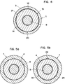
- Recesses 14 are provided on the conical surface of this cone 13, as can be seen from FIG. 4. These recesses 14 are worked into three areas of the cone 13, which are mutually offset by an angle of 120 °, by grinding, the depth of which is in the range of 0.2-0.4 mm.
- the driving piece 5 has two cams 15 at its end facing the cutting head 3. When the cutting head 3 is inserted, these cams 15 engage in a groove 16 machined therein. This positive connection transmits the torque from the reaming shaft 1 the cutting head 3.
- FIG. 2 shows a view of the cutting head 3 with the correspondingly attached cutting inserts 17.
- the retaining screw 8 has a hexagon socket 18 through which the retaining screw 8 can be screwed in and out.
- the cutting head shaft 4 which has a cylindrical shape, is slidably inserted into the cylindrical coaxial opening 2 of the reaming shaft 1.
- the cutting head 3 must be turned so that the cams 15 of the driving piece 5 engage in the groove 16 of the cutting head shaft 4.
- the cone 12 of the cutting head shaft 4 and the cone 13 of the reaming shaft 1 now lie on one another.
- the retaining screw 8 can now be screwed into the driving piece 5.
- FIG. 4 The situation as it is in the unscrewed state in the support of the two cones 12 and 18 is shown in Fig. 4.
- the cone 12 of the cutting head 3 is only in three areas 19, 20 and 21 on the cone 13 of the reamer shaft 1. There is a gap in the recesses 14, which are shown enlarged.
- the cutting head shaft 4 lies in the coaxial opening 2 of the reaming shaft 1, as shown in Fig.5a.
- the game between the cutting head shaft 4 and the coaxial opening is shown greatly enlarged.
- This deformation also affects the end region of the wall of the reamer shaft 1 facing the cutting head 3.
- the wall deforms in this area in such a way, as can be seen from FIG. 5 b, that the areas 28, 29 and 30 are pressed onto the cutting head shaft 4.
- the cutting head 3 is thereby in the reaming shaft 1 on the cone 12, since the locations of the cone 13 provided with recesses 14 never come into contact with the cone 12, on the three regions 19, 20 and 21 and on the cutting head shaft on the three regions 28, 29 and 30 kept free of play.
- the retaining screw 8 can be equipped with a head 22 having a conical shape.
- the inner surface 23 of the screw head hole of the cutting head 3 have a curved shape at their outer end.
- the conical head 22 of the retaining screw 8 rests on this curved shape.
- the retaining screw 8 is consequently used on the one hand for fastening the cutting head 3 to the reaming shaft 1 and on the other hand for adjusting the cutting head 3.
- the small thickness of the wall first causes the cone 13 of the reaming shaft 1 to be widened until an optimal connection between the cutting head 3 and the reaming shaft 1 is achieved before the cutting head 3 is widened, which is no longer in the range of the diameter tolerance Reamer lies through the conical head 22 of the retaining screw. This is because the force for deforming the cone 13 of the reaming shaft 1 is much less than the expansion and consequently the adjustment of the cutting head 3 by the conical head 22 of the retaining screw 8 because of the thin wall of the reaming shaft 1.
- a non-adjustable cutting head 3 can also be used for the same reaming shaft 1.
- the retaining screw 8 rests on the flat bottom of the bore of the cutting head 3.
- the coolant lubricant is supplied via a central bore 23 in the rear region of the reaming shaft 1.
- a circumferential groove 24 is incorporated, which is in line with the central one Bore 23 is connected via cross bores 25.
- a cover cap 26 is slid over the circumferential groove 24, which together with the circumferential groove 24 forms an annular channel which is closed toward the rear.
- the cover cap 26 Towards the cutting head 3, the cover cap 26 has an annular nozzle 27 through which the cooling lubricant is sprayed under pressure along the surface of the reaming shaft 1 to the cutting head 3.
- the cutting plates 17 of the cutting head 3 are thereby optimally supplied with cooling lubricant, regardless of how the teeth of the cutting heads are designed. Since the distance between the cutting plates 17 of the cutting head 3 and the ring nozzle 27 is not very large, the coolant-lubricant jet bridges this distance without problems.
Landscapes
- Engineering & Computer Science (AREA)
- Mechanical Engineering (AREA)
- Milling, Broaching, Filing, Reaming, And Others (AREA)
- Auxiliary Devices For Machine Tools (AREA)
- Jigs For Machine Tools (AREA)
- Drilling Tools (AREA)
Applications Claiming Priority (2)
| Application Number | Priority Date | Filing Date | Title |
|---|---|---|---|
| CH75591 | 1991-03-13 | ||
| CH755/91 | 1991-03-13 |
Publications (2)
| Publication Number | Publication Date |
|---|---|
| EP0504100A1 true EP0504100A1 (fr) | 1992-09-16 |
| EP0504100B1 EP0504100B1 (fr) | 1996-04-10 |
Family
ID=4194439
Family Applications (1)
| Application Number | Title | Priority Date | Filing Date |
|---|---|---|---|
| EP92810134A Expired - Lifetime EP0504100B1 (fr) | 1991-03-13 | 1992-02-25 | Alésoir à tête de coupe interchangeable |
Country Status (5)
| Country | Link |
|---|---|
| US (1) | US5163790A (fr) |
| EP (1) | EP0504100B1 (fr) |
| JP (1) | JP3153315B2 (fr) |
| AT (1) | ATE136480T1 (fr) |
| DE (1) | DE59205930D1 (fr) |
Cited By (4)
| Publication number | Priority date | Publication date | Assignee | Title |
|---|---|---|---|---|
| DE10009721A1 (de) * | 2000-03-01 | 2001-09-06 | Komet Stahlhalter Werkzeuge | Maschinenreibahle und Reibkopf für eine Maschinenreibahle |
| DE10009728A1 (de) * | 2000-03-01 | 2001-09-06 | Dihart Ag Dulliken | Reibwerkzeug mit Führungsschaft |
| WO2008155104A1 (fr) * | 2007-06-20 | 2008-12-24 | MAPAL Fabrik für Präzisionswerkzeuge Dr. Kress KG | Alésoir extensible |
| DE102021120357A1 (de) | 2021-08-05 | 2023-02-09 | Hartmetall-Werkzeugfabrik Paul Horn Gmbh | Schneideinsatz und werkzeug zur spanenden bearbeitung |
Families Citing this family (45)
| Publication number | Priority date | Publication date | Assignee | Title |
|---|---|---|---|---|
| CH690026A5 (de) * | 1994-07-02 | 2000-03-31 | Beck August Gmbh Co | Rotierendes Schaftwerkzeug. |
| US5775853A (en) * | 1996-09-03 | 1998-07-07 | Makino Inc. | Machining method and multi-function tool |
| US5873687A (en) * | 1997-04-16 | 1999-02-23 | Mori Seiki Co., Ltd. | Tool unit with hydraulic feed passage |
| DE19724855B4 (de) * | 1997-06-12 | 2007-08-09 | August Beck Gmbh & Co | Rotierendes Schaftwerkzeug und Verfahren zur Bearbeitung von Bohrungen mit einem derartigen Schaftwerkzeug |
| CN1247161C (zh) * | 2000-09-27 | 2006-03-29 | 库尔斯恩蒂斯股份公司 | 用于连接外科清理或钻孔器具零件的装置 |
| DE10048910A1 (de) * | 2000-10-02 | 2002-05-02 | Mapal Fab Praezision | Verbindungsstelle |
| SE524063C2 (sv) * | 2002-01-29 | 2004-06-22 | Sandvik Ab | Verktygskoppling för roterande verktyg där kopplingens hondel har ett triangulärt tvärsnitt |
| IL150013A (en) * | 2002-06-04 | 2007-06-17 | Gil Hecht | Swivel cutting tool |
| SE526762C2 (sv) * | 2002-06-17 | 2005-11-01 | Sandvik Intellectual Property | Han/hon-koppling uppvisande presspassning mellan delarna |
| US7785046B2 (en) * | 2002-07-17 | 2010-08-31 | Advanced Industries | Tool coolant application and direction assembly |
| US7134812B2 (en) * | 2002-07-17 | 2006-11-14 | Kevin Beckington | Tool coolant application and direction assembly |
| US20100270757A1 (en) * | 2002-07-17 | 2010-10-28 | Kevin Beckington | Tool coolant application and direction assembly |
| US7112020B2 (en) * | 2003-06-10 | 2006-09-26 | Kennametal Inc. | Cutting tool configured for improved engagement with a tool holder |
| DE50308700D1 (de) * | 2003-11-06 | 2008-01-10 | Urma Ag | Maschinenreibwerkzeug, Wechselkopf und Schaft |
| US7125207B2 (en) * | 2004-08-06 | 2006-10-24 | Kennametal Inc. | Tool holder with integral coolant channel and locking screw therefor |
| AT8511U1 (de) * | 2005-04-05 | 2006-09-15 | Ceratizit Austria Gmbh | Werkzeugaufbau |
| JP2007021646A (ja) * | 2005-07-15 | 2007-02-01 | Allied Material Corp | チップホルダ交換型穴加工用工具 |
| DE102005040587A1 (de) * | 2005-08-22 | 2007-03-01 | MAPAL Fabrik für Präzisionswerkzeuge Dr. Kress KG | Schnittstelle |
| TW200924879A (en) * | 2005-11-06 | 2009-06-16 | Iscar Ltd | Rotary cutting tool |
| US8328471B2 (en) | 2007-01-18 | 2012-12-11 | Kennametal Inc. | Cutting insert with internal coolant delivery and cutting assembly using the same |
| US7883299B2 (en) | 2007-01-18 | 2011-02-08 | Kennametal Inc. | Metal cutting system for effective coolant delivery |
| US8439608B2 (en) | 2007-01-18 | 2013-05-14 | Kennametal Inc. | Shim for a cutting insert and cutting insert-shim assembly with internal coolant delivery |
| US8454274B2 (en) | 2007-01-18 | 2013-06-04 | Kennametal Inc. | Cutting inserts |
| US8727673B2 (en) | 2007-01-18 | 2014-05-20 | Kennametal Inc. | Cutting insert with internal coolant delivery and surface feature for enhanced coolant flow |
| US9101985B2 (en) | 2007-01-18 | 2015-08-11 | Kennametal Inc. | Cutting insert assembly and components thereof |
| US20080175679A1 (en) * | 2007-01-18 | 2008-07-24 | Paul Dehnhardt Prichard | Milling cutter and milling insert with core and coolant delivery |
| US7625157B2 (en) * | 2007-01-18 | 2009-12-01 | Kennametal Inc. | Milling cutter and milling insert with coolant delivery |
| US7963729B2 (en) | 2007-01-18 | 2011-06-21 | Kennametal Inc. | Milling cutter and milling insert with coolant delivery |
| DE102007023168A1 (de) * | 2007-05-20 | 2008-11-27 | Gühring Ohg | Drehantreibbares spanabhebendes Werkzeug |
| DE102007023167A1 (de) * | 2007-05-20 | 2008-11-27 | Gühring Ohg | Spanabhebendes Werkzeug |
| JP4967863B2 (ja) * | 2007-07-05 | 2012-07-04 | 三菱マテリアル株式会社 | 穴加工工具 |
| US7955032B2 (en) | 2009-01-06 | 2011-06-07 | Kennametal Inc. | Cutting insert with coolant delivery and method of making the cutting insert |
| IL198378A (en) * | 2009-04-26 | 2013-11-28 | Iscar Ltd | Rotary cutting tools |
| DE102010014322B4 (de) | 2010-04-09 | 2015-04-23 | Kennametal Inc. | Werkzeugkopf für ein rotierendes Werkzeug |
| US8734062B2 (en) | 2010-09-02 | 2014-05-27 | Kennametal Inc. | Cutting insert assembly and components thereof |
| US8827599B2 (en) | 2010-09-02 | 2014-09-09 | Kennametal Inc. | Cutting insert assembly and components thereof |
| DE102012100976B4 (de) * | 2012-02-07 | 2014-04-24 | Franz Haimer Maschinenbau Kg | Einschraubwerkzeug und Werkzeugaufnahme für ein derartiges Einschraubwerkzeug |
| US9802256B2 (en) | 2012-02-07 | 2017-10-31 | Franz Haimer Maschinenbau Kg | Screw-in tool and tool holder for such a screw-in tool |
| DE102012107546A1 (de) * | 2012-08-17 | 2014-02-20 | Franz Haimer Maschinenbau Kg | Werkzeuganordnung |
| US9505059B2 (en) * | 2014-10-14 | 2016-11-29 | X'pole Precision Tools Inc. | Tools holder |
| DE102016205657B4 (de) * | 2016-04-06 | 2021-06-10 | Gühring KG | Spanabhebendes werkzeug zum entgraten von bohrungen |
| CN110270851B (zh) | 2018-03-15 | 2021-09-24 | 益壮企业有限公司 | 加工工具的组接中心定位结构 |
| TWI647036B (zh) * | 2018-03-15 | 2019-01-11 | 益壯企業有限公司 | 加工工具的組接中心定位結構 |
| WO2021084315A1 (fr) * | 2019-10-31 | 2021-05-06 | Dino Paoli S.R.L. | Ensemble de liaison douille-arbre d'une clé à impact pneumatique |
| US11391553B2 (en) * | 2020-04-15 | 2022-07-19 | Steve Knowles | Precision ammunition cartridge reaming device |
Citations (5)
| Publication number | Priority date | Publication date | Assignee | Title |
|---|---|---|---|---|
| US1439567A (en) * | 1919-11-14 | 1922-12-19 | J Faessler Mfg Company | Reamer |
| US2796264A (en) * | 1954-03-04 | 1957-06-18 | Portage Machine Company | Keeper key-universal type |
| US3320833A (en) * | 1964-11-23 | 1967-05-23 | Detroit Reamer & Tool Company | Deep-hole drill and reamer |
| GB1160769A (en) * | 1966-10-28 | 1969-08-06 | Padley & Venables Ltd | Improvements relating to Connecting of Tapered Spigots and Sockets |
| CH666643A5 (en) * | 1985-07-29 | 1988-08-15 | Polytool Ag | Reamer with cutting head of adjustable dia. - has bolt with conical head which expands reamer dia. |
Family Cites Families (7)
| Publication number | Priority date | Publication date | Assignee | Title |
|---|---|---|---|---|
| US2383688A (en) * | 1943-07-26 | 1945-08-28 | Tungsten Carbide Tool Company | Boring tool |
| DE2301748A1 (de) | 1973-01-13 | 1974-07-18 | Junginger Ju Geraete | Verstellbare spreizreibahle |
| CH574295A5 (fr) * | 1974-10-18 | 1976-04-15 | Merz Ag | |
| DE3234238A1 (de) * | 1982-09-15 | 1984-03-15 | August Beck GmbH & Co, 7472 Winterlingen | Aufbohrer mit wendeplatte |
| DE3314591A1 (de) * | 1983-04-22 | 1984-10-25 | Montanwerke Walter GmbH, 7400 Tübingen | Mehrteiliges spannsystem, insbesondere fuer rundlaufende werkzeuge |
| EP0215144B1 (fr) * | 1985-09-16 | 1989-05-03 | Dihart AG | Alésoir avec dispositif de refroidissement |
| SE457623B (sv) * | 1987-04-21 | 1989-01-16 | Sandvik Ab | Verktygskoppling |
-
1992
- 1992-02-25 EP EP92810134A patent/EP0504100B1/fr not_active Expired - Lifetime
- 1992-02-25 AT AT92810134T patent/ATE136480T1/de not_active IP Right Cessation
- 1992-02-25 DE DE59205930T patent/DE59205930D1/de not_active Expired - Fee Related
- 1992-03-06 US US07/847,361 patent/US5163790A/en not_active Expired - Fee Related
- 1992-03-12 JP JP05301192A patent/JP3153315B2/ja not_active Expired - Fee Related
Patent Citations (5)
| Publication number | Priority date | Publication date | Assignee | Title |
|---|---|---|---|---|
| US1439567A (en) * | 1919-11-14 | 1922-12-19 | J Faessler Mfg Company | Reamer |
| US2796264A (en) * | 1954-03-04 | 1957-06-18 | Portage Machine Company | Keeper key-universal type |
| US3320833A (en) * | 1964-11-23 | 1967-05-23 | Detroit Reamer & Tool Company | Deep-hole drill and reamer |
| GB1160769A (en) * | 1966-10-28 | 1969-08-06 | Padley & Venables Ltd | Improvements relating to Connecting of Tapered Spigots and Sockets |
| CH666643A5 (en) * | 1985-07-29 | 1988-08-15 | Polytool Ag | Reamer with cutting head of adjustable dia. - has bolt with conical head which expands reamer dia. |
Cited By (8)
| Publication number | Priority date | Publication date | Assignee | Title |
|---|---|---|---|---|
| DE10009721A1 (de) * | 2000-03-01 | 2001-09-06 | Komet Stahlhalter Werkzeuge | Maschinenreibahle und Reibkopf für eine Maschinenreibahle |
| DE10009728A1 (de) * | 2000-03-01 | 2001-09-06 | Dihart Ag Dulliken | Reibwerkzeug mit Führungsschaft |
| US6830502B2 (en) | 2000-03-01 | 2004-12-14 | Dihart Ag | Reaming tool with a guide shank |
| US6896450B2 (en) | 2000-03-01 | 2005-05-24 | Komet Praezisionswerkzeuge Robert Breuning Gmbh | Machine reamer and reaming head for a machine reamer |
| WO2008155104A1 (fr) * | 2007-06-20 | 2008-12-24 | MAPAL Fabrik für Präzisionswerkzeuge Dr. Kress KG | Alésoir extensible |
| EP2388098A1 (fr) * | 2007-06-20 | 2011-11-23 | MAPAL Fabrik für Präzisionswerkzeuge Dr. Kress KG | Alésoir extensible |
| US8790051B2 (en) | 2007-06-20 | 2014-07-29 | Mapal Fabrik Fur Prazisionswerkzeuge Dr. Kress Kg | Expandable reamer |
| DE102021120357A1 (de) | 2021-08-05 | 2023-02-09 | Hartmetall-Werkzeugfabrik Paul Horn Gmbh | Schneideinsatz und werkzeug zur spanenden bearbeitung |
Also Published As
| Publication number | Publication date |
|---|---|
| EP0504100B1 (fr) | 1996-04-10 |
| JPH0592316A (ja) | 1993-04-16 |
| US5163790A (en) | 1992-11-17 |
| DE59205930D1 (de) | 1996-05-15 |
| JP3153315B2 (ja) | 2001-04-09 |
| ATE136480T1 (de) | 1996-04-15 |
Similar Documents
| Publication | Publication Date | Title |
|---|---|---|
| EP0504100B1 (fr) | Alésoir à tête de coupe interchangeable | |
| DE19505754C1 (de) | Stanzstempeleinheit | |
| DE2748093C2 (fr) | ||
| EP0964764B1 (fr) | Outil de coupe pour alesage et chanfreinage | |
| DE3875534T2 (de) | Schneidwerkzeug fuer metall. | |
| DE60224252T2 (de) | Drehendes Werkzeug zur spanabhebenden Bearbeitung | |
| DE10261748B4 (de) | Stanzwerkzeug | |
| DE10326928B4 (de) | Schnittstelle zwischen zwei Teilelementen eines Werkzeugsystems | |
| EP0859679A1 (fr) | Outil de per age avec pointe rempla able | |
| DE3744547A1 (de) | Schnellwechsel-spindelspannhuelse fuer werkzeughalter | |
| DE102016105354B4 (de) | Spanabhebendes Werkzeug | |
| EP3467255A1 (fr) | Porte-burin | |
| DE1477836B1 (de) | Einstellbarer Werkzeugeinsatz | |
| DE3108438A1 (de) | Bohrwerkzeug | |
| EP0193020B1 (fr) | Dispositif d'outillage avec tête interchangeable | |
| EP2379260B1 (fr) | Outil pour usinage par enlèvement de copeaux, en particulier outil pour tournage longitudinal | |
| DE2831140A1 (de) | Spannzange | |
| DE69213229T2 (de) | Werkzeug für die bearbeitung schwerzugänglichen räumen, beispielsweise für innendrehen | |
| EP2114601B1 (fr) | Porte-outil | |
| EP3102355A1 (fr) | Élément de tête d'outil pour la fabrication d'une tête d'outil, tête d'outil et moyen de réception d'outil ainsi que procédé de fabrication d'un élément de tête d'outil et d'une tête d'outil | |
| DE2736387C2 (de) | Zerspanungswerkzeug | |
| DE102004029974A1 (de) | Verbindungssystem | |
| EP0285704A2 (fr) | Système de serrage composé de plusieurs parties en particulier pour outils tournant rond | |
| DE2854121C2 (de) | An ein Maschinenteil ansetzbare Vorrichtung zum Ausstechen von Ringlippen dort in Bohrungen eingestemmter Lagerbüchsen | |
| CH688029A5 (de) | Nachstellbare Reibahle mit auswechselbarer Schneidhuelse. |
Legal Events
| Date | Code | Title | Description |
|---|---|---|---|
| PUAI | Public reference made under article 153(3) epc to a published international application that has entered the european phase |
Free format text: ORIGINAL CODE: 0009012 |
|
| AK | Designated contracting states |
Kind code of ref document: A1 Designated state(s): AT CH DE ES FR GB IT LI |
|
| 17P | Request for examination filed |
Effective date: 19930311 |
|
| 17Q | First examination report despatched |
Effective date: 19941020 |
|
| GRAH | Despatch of communication of intention to grant a patent |
Free format text: ORIGINAL CODE: EPIDOS IGRA |
|
| GRAA | (expected) grant |
Free format text: ORIGINAL CODE: 0009210 |
|
| AK | Designated contracting states |
Kind code of ref document: B1 Designated state(s): AT CH DE ES FR GB IT LI |
|
| PG25 | Lapsed in a contracting state [announced via postgrant information from national office to epo] |
Ref country code: ES Free format text: THE PATENT HAS BEEN ANNULLED BY A DECISION OF A NATIONAL AUTHORITY Effective date: 19960410 |
|
| REF | Corresponds to: |
Ref document number: 136480 Country of ref document: AT Date of ref document: 19960415 Kind code of ref document: T |
|
| REG | Reference to a national code |
Ref country code: CH Ref legal event code: NV Representative=s name: BOVARD AG PATENTANWAELTE |
|
| REF | Corresponds to: |
Ref document number: 59205930 Country of ref document: DE Date of ref document: 19960515 |
|
| ET | Fr: translation filed | ||
| ITF | It: translation for a ep patent filed | ||
| GBT | Gb: translation of ep patent filed (gb section 77(6)(a)/1977) |
Effective date: 19960628 |
|
| PLBE | No opposition filed within time limit |
Free format text: ORIGINAL CODE: 0009261 |
|
| 26N | No opposition filed | ||
| REG | Reference to a national code |
Ref country code: GB Ref legal event code: IF02 |
|
| PGFP | Annual fee paid to national office [announced via postgrant information from national office to epo] |
Ref country code: AT Payment date: 20040108 Year of fee payment: 13 |
|
| PGFP | Annual fee paid to national office [announced via postgrant information from national office to epo] |
Ref country code: FR Payment date: 20040112 Year of fee payment: 13 |
|
| PGFP | Annual fee paid to national office [announced via postgrant information from national office to epo] |
Ref country code: GB Payment date: 20040115 Year of fee payment: 13 |
|
| PGFP | Annual fee paid to national office [announced via postgrant information from national office to epo] |
Ref country code: DE Payment date: 20040116 Year of fee payment: 13 |
|
| PGFP | Annual fee paid to national office [announced via postgrant information from national office to epo] |
Ref country code: CH Payment date: 20040213 Year of fee payment: 13 |
|
| PG25 | Lapsed in a contracting state [announced via postgrant information from national office to epo] |
Ref country code: IT Free format text: LAPSE BECAUSE OF NON-PAYMENT OF DUE FEES;WARNING: LAPSES OF ITALIAN PATENTS WITH EFFECTIVE DATE BEFORE 2007 MAY HAVE OCCURRED AT ANY TIME BEFORE 2007. THE CORRECT EFFECTIVE DATE MAY BE DIFFERENT FROM THE ONE RECORDED. Effective date: 20050225 Ref country code: GB Free format text: LAPSE BECAUSE OF NON-PAYMENT OF DUE FEES Effective date: 20050225 Ref country code: AT Free format text: LAPSE BECAUSE OF NON-PAYMENT OF DUE FEES Effective date: 20050225 |
|
| PG25 | Lapsed in a contracting state [announced via postgrant information from national office to epo] |
Ref country code: LI Free format text: LAPSE BECAUSE OF NON-PAYMENT OF DUE FEES Effective date: 20050228 Ref country code: CH Free format text: LAPSE BECAUSE OF NON-PAYMENT OF DUE FEES Effective date: 20050228 |
|
| PG25 | Lapsed in a contracting state [announced via postgrant information from national office to epo] |
Ref country code: DE Free format text: LAPSE BECAUSE OF NON-PAYMENT OF DUE FEES Effective date: 20050901 |
|
| GBPC | Gb: european patent ceased through non-payment of renewal fee |
Effective date: 20050225 |
|
| REG | Reference to a national code |
Ref country code: CH Ref legal event code: PL |
|
| PG25 | Lapsed in a contracting state [announced via postgrant information from national office to epo] |
Ref country code: FR Free format text: LAPSE BECAUSE OF NON-PAYMENT OF DUE FEES Effective date: 20051031 |
|
| REG | Reference to a national code |
Ref country code: FR Ref legal event code: ST Effective date: 20051031 |