EP0504100A1 - Reamer with exchangeable cutting head - Google Patents
Reamer with exchangeable cutting head Download PDFInfo
- Publication number
- EP0504100A1 EP0504100A1 EP92810134A EP92810134A EP0504100A1 EP 0504100 A1 EP0504100 A1 EP 0504100A1 EP 92810134 A EP92810134 A EP 92810134A EP 92810134 A EP92810134 A EP 92810134A EP 0504100 A1 EP0504100 A1 EP 0504100A1
- Authority
- EP
- European Patent Office
- Prior art keywords
- cutting head
- shaft
- reamer
- cone
- reaming
- Prior art date
- Legal status (The legal status is an assumption and is not a legal conclusion. Google has not performed a legal analysis and makes no representation as to the accuracy of the status listed.)
- Granted
Links
Images

Classifications
-
- B—PERFORMING OPERATIONS; TRANSPORTING
- B23—MACHINE TOOLS; METAL-WORKING NOT OTHERWISE PROVIDED FOR
- B23B—TURNING; BORING
- B23B31/00—Chucks; Expansion mandrels; Adaptations thereof for remote control
- B23B31/02—Chucks
- B23B31/10—Chucks characterised by the retaining or gripping devices or their immediate operating means
- B23B31/11—Retention by threaded connection
- B23B31/1107—Retention by threaded connection for conical parts
- B23B31/1122—Retention by threaded connection for conical parts using cylindrical threads
-
- B—PERFORMING OPERATIONS; TRANSPORTING
- B23—MACHINE TOOLS; METAL-WORKING NOT OTHERWISE PROVIDED FOR
- B23B—TURNING; BORING
- B23B31/00—Chucks; Expansion mandrels; Adaptations thereof for remote control
- B23B31/02—Chucks
- B23B31/10—Chucks characterised by the retaining or gripping devices or their immediate operating means
- B23B31/11—Retention by threaded connection
- B23B31/1107—Retention by threaded connection for conical parts
-
- B—PERFORMING OPERATIONS; TRANSPORTING
- B23—MACHINE TOOLS; METAL-WORKING NOT OTHERWISE PROVIDED FOR
- B23D—PLANING; SLOTTING; SHEARING; BROACHING; SAWING; FILING; SCRAPING; LIKE OPERATIONS FOR WORKING METAL BY REMOVING MATERIAL, NOT OTHERWISE PROVIDED FOR
- B23D77/00—Reaming tools
- B23D77/06—Reaming with means for compensating wear
- B23D77/10—Reaming with means for compensating wear by expanding a tube-like non-slotted part of the tool body
-
- Y—GENERAL TAGGING OF NEW TECHNOLOGICAL DEVELOPMENTS; GENERAL TAGGING OF CROSS-SECTIONAL TECHNOLOGIES SPANNING OVER SEVERAL SECTIONS OF THE IPC; TECHNICAL SUBJECTS COVERED BY FORMER USPC CROSS-REFERENCE ART COLLECTIONS [XRACs] AND DIGESTS
- Y10—TECHNICAL SUBJECTS COVERED BY FORMER USPC
- Y10T—TECHNICAL SUBJECTS COVERED BY FORMER US CLASSIFICATION
- Y10T279/00—Chucks or sockets
- Y10T279/16—Longitudinal screw clamp
-
- Y—GENERAL TAGGING OF NEW TECHNOLOGICAL DEVELOPMENTS; GENERAL TAGGING OF CROSS-SECTIONAL TECHNOLOGIES SPANNING OVER SEVERAL SECTIONS OF THE IPC; TECHNICAL SUBJECTS COVERED BY FORMER USPC CROSS-REFERENCE ART COLLECTIONS [XRACs] AND DIGESTS
- Y10—TECHNICAL SUBJECTS COVERED BY FORMER USPC
- Y10T—TECHNICAL SUBJECTS COVERED BY FORMER US CLASSIFICATION
- Y10T408/00—Cutting by use of rotating axially moving tool
- Y10T408/44—Cutting by use of rotating axially moving tool with means to apply transient, fluent medium to work or product
- Y10T408/45—Cutting by use of rotating axially moving tool with means to apply transient, fluent medium to work or product including Tool with duct
-
- Y—GENERAL TAGGING OF NEW TECHNOLOGICAL DEVELOPMENTS; GENERAL TAGGING OF CROSS-SECTIONAL TECHNOLOGIES SPANNING OVER SEVERAL SECTIONS OF THE IPC; TECHNICAL SUBJECTS COVERED BY FORMER USPC CROSS-REFERENCE ART COLLECTIONS [XRACs] AND DIGESTS
- Y10—TECHNICAL SUBJECTS COVERED BY FORMER USPC
- Y10T—TECHNICAL SUBJECTS COVERED BY FORMER US CLASSIFICATION
- Y10T408/00—Cutting by use of rotating axially moving tool
- Y10T408/89—Tool or Tool with support
- Y10T408/909—Having peripherally spaced cutting edges
- Y10T408/9098—Having peripherally spaced cutting edges with means to retain Tool to support
- Y10T408/90993—Screw driven means
-
- Y—GENERAL TAGGING OF NEW TECHNOLOGICAL DEVELOPMENTS; GENERAL TAGGING OF CROSS-SECTIONAL TECHNOLOGIES SPANNING OVER SEVERAL SECTIONS OF THE IPC; TECHNICAL SUBJECTS COVERED BY FORMER USPC CROSS-REFERENCE ART COLLECTIONS [XRACs] AND DIGESTS
- Y10—TECHNICAL SUBJECTS COVERED BY FORMER USPC
- Y10T—TECHNICAL SUBJECTS COVERED BY FORMER US CLASSIFICATION
- Y10T408/00—Cutting by use of rotating axially moving tool
- Y10T408/94—Tool-support
- Y10T408/95—Tool-support with tool-retaining means
Definitions
- the invention relates to a reamer with a replaceable cutting head according to the preamble of claim 1.
- CH-PS 574 295 shows a reamer with an exchangeable cutting head which is provided with a shoulder formed as a cone. This cone of the cutting head is inserted into a correspondingly shaped receiving opening in the reamer shaft. The cutting head is screwed to the reamer shaft using a screw bolt. The conical seat between the cutting head and the reamer shaft guarantees a play-free connection.
- this conical seat has the disadvantage that the cutting head is pressed into the reaming shaft, particularly when the feed forces are greater, and is jammed, in particular because the conical seat is self-locking.
- the cutting head is difficult to remove from the reaming shaft, which means that the screw pin in particular is subject to great wear and tear, and even damage can occur.
- An adjustable reamer can be seen from EP-PS 215 144.
- the cutting head and reaming shaft are made in one piece, the cutting head cannot be replaced.
- a screw with a conically shaped head is arranged axially in an opening of the cutting head.
- the conically shaped head of this screw rests on correspondingly shaped inner surfaces in the cutting head of the reamer.
- the cutting head is pressed apart by tightening the screw.
- the wear and tear reaming can be compensated for by the adjustability, the service life of the tool is increased.
- the cooling lubricant is brought through a central hole from behind through the reamer shaft into the inner part of the cutting head.
- the cooling lubricant is sprayed into the area of the reamer blades through fine holes at an angle between the reamer blades.
- the drilling of the holes between the reamers is very complex. It is less suitable for interchangeable cutting heads, since their production would be more expensive.
- the object of the invention is to provide a reamer with an interchangeable cutting head, in which a play-free connection is ensured between the reamer shank and the cutting head and the risk of the connection jamming is eliminated, so that the cutting head can be easily released from the reamer shank.
- these interchangeable cutting heads should be adjustable.
- the coolant-lubricant supply should be designed in such a way that any type of cutting heads can be used without the individual cutting heads having to be provided with additional bores, and that optimum cooling and lubrication is nevertheless ensured for each cutting head.
- Another advantage is that the torque is not transmitted from the reaming shaft to the cutting head via the conical seat, but rather via a driving piece which is fastened in the reaming shaft and is provided with cams which protrude into a groove in the cutting head.
- the driving piece is also provided with an internal thread in which the thread of the retaining screw engages.
- the driver piece is advantageously held with play in the reaming shaft, so that it can adapt to the retaining screw during the screwing-in process.
- a further advantageous embodiment of the invention is achieved if the retaining screw is equipped with a conical head which bears on the correspondingly shaped inner surface of the cutting head. This ensures that the cutting head can be readjusted at the same time without that additional funds are required.
- the cooling lubricant is supplied from the outside, that is, not through the cutting head.
- the cooling lubricant emerges from an annular nozzle which is mounted in the reaming shaft and flows along the peripheral surface of the reaming shaft over the cutting head surface to the cutting edges. Regardless of the arrangement of the cutting edges in the cutting head used, the cooling and lubrication is optimal at all times.
- the 1 has a coaxial opening 2, into which the cutting head shaft 4 of the cutting head 3 can be inserted.
- the coaxial opening 2 is cylindrical.
- a driving piece 5 is inserted, which is held by a cross pin 6, which penetrates both the driving piece 5 and the wall of the reaming shaft.
- the seat of the cross pin 6 on the driving piece is designed with play, just as the driving piece 5 has a play with respect to the wall of the reaming shaft 1.
- An internal thread 7 is incorporated into the driving piece 5, into which the retaining screw 8 can be screwed.
- the holding screw 8 is guided through a coaxial opening 9 in the cutting head 3. With the cylindrical head 10, the retaining screw 8 rests on the annular surface 11, as a result of which the cutting head 3 can be screwed into the reaming shaft 1.
- a cone 12 is attached to the cutting head shaft 4, which has an incline of the order of 45 ° to 60 ° and which tapers towards the cutting head shaft.
- the wall which forms the coaxial opening 2 of the reaming shaft 1 is closed at its end on the cutting head side with a cone 13 which opens outwards and which corresponds to the cone 12 of the cutting head shaft 1.
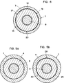
- Recesses 14 are provided on the conical surface of this cone 13, as can be seen from FIG. 4. These recesses 14 are worked into three areas of the cone 13, which are mutually offset by an angle of 120 °, by grinding, the depth of which is in the range of 0.2-0.4 mm.
- the driving piece 5 has two cams 15 at its end facing the cutting head 3. When the cutting head 3 is inserted, these cams 15 engage in a groove 16 machined therein. This positive connection transmits the torque from the reaming shaft 1 the cutting head 3.
- FIG. 2 shows a view of the cutting head 3 with the correspondingly attached cutting inserts 17.
- the retaining screw 8 has a hexagon socket 18 through which the retaining screw 8 can be screwed in and out.
- the cutting head shaft 4 which has a cylindrical shape, is slidably inserted into the cylindrical coaxial opening 2 of the reaming shaft 1.
- the cutting head 3 must be turned so that the cams 15 of the driving piece 5 engage in the groove 16 of the cutting head shaft 4.
- the cone 12 of the cutting head shaft 4 and the cone 13 of the reaming shaft 1 now lie on one another.
- the retaining screw 8 can now be screwed into the driving piece 5.
- FIG. 4 The situation as it is in the unscrewed state in the support of the two cones 12 and 18 is shown in Fig. 4.
- the cone 12 of the cutting head 3 is only in three areas 19, 20 and 21 on the cone 13 of the reamer shaft 1. There is a gap in the recesses 14, which are shown enlarged.
- the cutting head shaft 4 lies in the coaxial opening 2 of the reaming shaft 1, as shown in Fig.5a.
- the game between the cutting head shaft 4 and the coaxial opening is shown greatly enlarged.
- This deformation also affects the end region of the wall of the reamer shaft 1 facing the cutting head 3.
- the wall deforms in this area in such a way, as can be seen from FIG. 5 b, that the areas 28, 29 and 30 are pressed onto the cutting head shaft 4.
- the cutting head 3 is thereby in the reaming shaft 1 on the cone 12, since the locations of the cone 13 provided with recesses 14 never come into contact with the cone 12, on the three regions 19, 20 and 21 and on the cutting head shaft on the three regions 28, 29 and 30 kept free of play.
- the retaining screw 8 can be equipped with a head 22 having a conical shape.
- the inner surface 23 of the screw head hole of the cutting head 3 have a curved shape at their outer end.
- the conical head 22 of the retaining screw 8 rests on this curved shape.
- the retaining screw 8 is consequently used on the one hand for fastening the cutting head 3 to the reaming shaft 1 and on the other hand for adjusting the cutting head 3.
- the small thickness of the wall first causes the cone 13 of the reaming shaft 1 to be widened until an optimal connection between the cutting head 3 and the reaming shaft 1 is achieved before the cutting head 3 is widened, which is no longer in the range of the diameter tolerance Reamer lies through the conical head 22 of the retaining screw. This is because the force for deforming the cone 13 of the reaming shaft 1 is much less than the expansion and consequently the adjustment of the cutting head 3 by the conical head 22 of the retaining screw 8 because of the thin wall of the reaming shaft 1.
- a non-adjustable cutting head 3 can also be used for the same reaming shaft 1.
- the retaining screw 8 rests on the flat bottom of the bore of the cutting head 3.
- the coolant lubricant is supplied via a central bore 23 in the rear region of the reaming shaft 1.
- a circumferential groove 24 is incorporated, which is in line with the central one Bore 23 is connected via cross bores 25.
- a cover cap 26 is slid over the circumferential groove 24, which together with the circumferential groove 24 forms an annular channel which is closed toward the rear.
- the cover cap 26 Towards the cutting head 3, the cover cap 26 has an annular nozzle 27 through which the cooling lubricant is sprayed under pressure along the surface of the reaming shaft 1 to the cutting head 3.
- the cutting plates 17 of the cutting head 3 are thereby optimally supplied with cooling lubricant, regardless of how the teeth of the cutting heads are designed. Since the distance between the cutting plates 17 of the cutting head 3 and the ring nozzle 27 is not very large, the coolant-lubricant jet bridges this distance without problems.
Landscapes
- Engineering & Computer Science (AREA)
- Mechanical Engineering (AREA)
- Milling, Broaching, Filing, Reaming, And Others (AREA)
- Auxiliary Devices For Machine Tools (AREA)
- Jigs For Machine Tools (AREA)
- Drilling Tools (AREA)
Abstract
Description
Die Erfindung betrifft eine Reibahle mit auswechselbarem Schneidkopf gemäss dem Oberbegriff des Anspruchs 1.The invention relates to a reamer with a replaceable cutting head according to the preamble of
Derartige Reibahlen sind bekannt. So zeigt beispielsweise die CH-PS 574 295 eine Reibahle mit auswechselbarem Schneidkopf, der mit einem als Konus gebildeten Ansatz versehen ist. Dieser Konus des Schneidkopfes wird in eine entsprechend geformte Aufnahmeöffnung im Reibahlenschaft eingeführt. Der Schneidkopf wird über einen Schraubenbolzen mit dem Reibahlenschaft verschraubt. Durch den konischen Sitz zwischen Schneidkopf und Reibahlenschaft wird eine spielfreie Verbindung garantiert.Such reamers are known. For example, CH-PS 574 295 shows a reamer with an exchangeable cutting head which is provided with a shoulder formed as a cone. This cone of the cutting head is inserted into a correspondingly shaped receiving opening in the reamer shaft. The cutting head is screwed to the reamer shaft using a screw bolt. The conical seat between the cutting head and the reamer shaft guarantees a play-free connection.
Dieser konische Sitz weist aber den Nachteil auf, dass der Schneidkopf insbesondere bei grösseren Vorschubkräften in den Reibahlenschaft eingedrückt wird und sich festklemmt, insbesondere auch weil der konische Sitz selbsthemmend ist. Der Schneidkopf lässt sich nur schwer aus dem Reibahlenschaft herausnehmen, wodurch insbesondere der Verschraubungsstift-einem grossen Verschleiss unterworfen ist, und sogar Beschädigungen auftreten können. Bei derartigen Reibahlen mit auswechselbaren Schneidköpfen ist nicht vorgesehen, die Schneidköpfe mit einer Nachstelleinrichtung auszurüsten.However, this conical seat has the disadvantage that the cutting head is pressed into the reaming shaft, particularly when the feed forces are greater, and is jammed, in particular because the conical seat is self-locking. The cutting head is difficult to remove from the reaming shaft, which means that the screw pin in particular is subject to great wear and tear, and even damage can occur. In such reamers with interchangeable cutting heads, there is no provision for the cutting heads to be equipped with an adjusting device.
Eine nachstellbare Reibahle ist aus der EP-PS 215 144 ersichtlich. Bei dieser Ausführungsart sind Schneidkopf und Reibahlenschaft aus einem Stück gefertigt, der Schneidkopf ist nicht auswechselbar. Zur Nachstellung des Schneidkopfes ist axial in einer Oeffnung des Schneidkopfs eine Schraube mit einem konisch geformten Kopf angeordnet. Der konisch geformte Kopf dieser Schraube liegt an entsprechend geformten Innenflächen im Schneidkopf der Reibahle an. Durch Anziehen der Schraube wird der Schneidkopf auseinandergepresst. Die Abnützung der Reibahlenschneiden lässt sich durch die Nachstellbarkeit ausgleichen, die Lebensdauer des Werkzeuges wird erhöht.An adjustable reamer can be seen from EP-PS 215 144. In this embodiment, the cutting head and reaming shaft are made in one piece, the cutting head cannot be replaced. To readjust the cutting head, a screw with a conically shaped head is arranged axially in an opening of the cutting head. The conically shaped head of this screw rests on correspondingly shaped inner surfaces in the cutting head of the reamer. The cutting head is pressed apart by tightening the screw. The wear and tear reaming can be compensated for by the adjustability, the service life of the tool is increased.
Bei dieser Ausführung wird das Kühl-Schmiermittel durch eine zentrale Bohrung von hinten durch den Reibahlenschaft in den inneren Teil des Schneidkopfes gebracht. Durch schräg angebrachte feine Bohrungen zwischen den Reibahlenschneiden wird das Kühl-Schmiermittel in den Bereich der Reibahlenschneiden gespritzt. Das Anbringen der Bohrungen zwischen den Reibahlenschneiden ist sehr aufwendig. Es eignet sich weniger bei auswechselbaren Schneidköpfen, da deren Herstellung zusätzlich verteuert würde.In this version, the cooling lubricant is brought through a central hole from behind through the reamer shaft into the inner part of the cutting head. The cooling lubricant is sprayed into the area of the reamer blades through fine holes at an angle between the reamer blades. The drilling of the holes between the reamers is very complex. It is less suitable for interchangeable cutting heads, since their production would be more expensive.
Die Aufgabe der Erfindung besteht darin, eine Reibahle mit auswechselbarem Schneidkopf zu schaffen, bei welcher zwischen Reibahlenschaft und Schneidkopf eine spielfreie Verbindung gewährleistet und, die Gefahr eines Verklemmens der Verbindung eliminiert ist, so dass ein leichtes Lösen des Schneidkopfs aus dem Reibahlenschaft möglich wird.The object of the invention is to provide a reamer with an interchangeable cutting head, in which a play-free connection is ensured between the reamer shank and the cutting head and the risk of the connection jamming is eliminated, so that the cutting head can be easily released from the reamer shank.
Erfindungsgemäss erfolgt die Lösung dieser Aufgabe gemäss den Merkmalen des Anspruchs 1.According to the invention, this object is achieved according to the features of
Des weiteren sollen diese auswechselbaren Schneidköpfe nachstellbar sein. Gleichzeitig soll die Kühl-Schmiermittelzuführung so gestaltet sein, dass jegliche Art von Schneidköpfen anwendbar ist, ohne dass die einzelnen Schneidköpfe mit zusätzlichen Bohrungen versehen sein müssen, und dass trotzdem für jeden Schneidkopf eine optimale Kühlung und Schmierung gewährleistet ist.Furthermore, these interchangeable cutting heads should be adjustable. At the same time, the coolant-lubricant supply should be designed in such a way that any type of cutting heads can be used without the individual cutting heads having to be provided with additional bores, and that optimum cooling and lubrication is nevertheless ensured for each cutting head.
Ein optimaler spielfreier Sitz zwischen Reibahlenschaft und Schneidkopf wird erreicht, wenn der Kegel am Reibahlenschaft drei Bereiche, die durch Schleifen vertieft sind, aufweist, und die um je 120° versetzt sind. Beim Einsetzen des Schneidkopfes liegt dessen Kegel an drei Stellen auf dem Gegenkegel des Reibahlenschaftes an, wodurch seine Lage bestimmt ist. Beim Anziehen der Halteschraube werden die Auflagestellen im Kegel des Reibahlenschaftes nach aussen gedrückt. Die nicht anliegenden Bereiche werden dadurch nach innen gezogen. Dadurch verformt sich auch die Wandung des Reibahlenschaftes, wodurch zusätzlich der zylinderförmige Schneidkopfschaft an drei jeweils zwischen den Auflagestellen des Kegels liegenden Bereichen gehalten wird. Der Schneidkopf ist dadurch spielfrei gehalten. Da die Kegelwinkel so gewählt werden, dass keine Selbsthemmung besteht, ist ein Herausnehmen des Schneidkopfes problemlos möglich. Beim Lösen der Halteschraube federt der Kegel des Reibahlenschaftes in seine ursprüngliche Form zurück. Der Schneidkopf wird freigegeben.An optimal backlash-free fit between the reamer shaft and cutting head is achieved if the cone on the reamer shaft has three areas, which are deepened by grinding, and which are offset by 120 ° each. When inserting the cutting head, its cone is in contact three places on the counter cone of the reamer shaft, which determines its position. When the retaining screw is tightened, the support points in the cone of the reamer shaft are pressed outwards. The areas not in contact are thereby drawn inwards. As a result, the wall of the reaming shaft also deforms, as a result of which the cylindrical cutting head shaft is additionally held at three regions each lying between the contact points of the cone. This keeps the cutting head free of play. Since the taper angles are chosen so that there is no self-locking, the cutting head can be removed without any problems. When the retaining screw is loosened, the cone of the reaming shaft springs back into its original shape. The cutting head is released.
Von Vorteil ist weiterhin, dass das Drehmoment nicht über dem Kegelsitz vom Reibahlenschaft auf den Schneidkopf übertragen wird, sondern über ein Mitnahmestück, welches im Reibahlenschaft befestigt ist und mit Nocken versehen ist, die in eine Nut im Schneidkopf hineinragen. Das Mitnahmestück ist gleichzeitig mit einem Innengewinde versehen, in welches das Gewinde der Halteschraube eingreift.Another advantage is that the torque is not transmitted from the reaming shaft to the cutting head via the conical seat, but rather via a driving piece which is fastened in the reaming shaft and is provided with cams which protrude into a groove in the cutting head. The driving piece is also provided with an internal thread in which the thread of the retaining screw engages.
Um das Einschrauben der Halteschraube zu erleichtern, ist das Mitnehmerstück in vorteilhafter Weise mit Spiel im Reibahlenschaft gehalten, so dass es sich an die Halteschraube während des Einschraubvorganges anpassen kann.In order to facilitate screwing in the retaining screw, the driver piece is advantageously held with play in the reaming shaft, so that it can adapt to the retaining screw during the screwing-in process.
Eine weitere vorteilhafte Ausgestaltung der Erfindung wird erreicht, wenn die Halteschraube mit einem kegelförmigen Kopf ausgerüstet ist, welcher an der entsprechend geformten Innenfläche des Schneidkopfes anliegt. Dadurch wird erreicht, dass mit der Halteschraube gleichzeitig der Schneidkopf nachgestellt werden kann, ohne dass zusätzliche Mittel dazu notwendig sind.A further advantageous embodiment of the invention is achieved if the retaining screw is equipped with a conical head which bears on the correspondingly shaped inner surface of the cutting head. This ensures that the cutting head can be readjusted at the same time without that additional funds are required.
In vorteilhafter Weise, weil die Schneidköpfe auswechselbar sind, erfolgt die Zuführung des Kühl-Schmiermittels von aussen, das heisst nicht durch den Schneidkopf. Das Kühl-Schmiermittel tritt aus einer ringförmigen Düse, die im Reibahlenschaft angebracht ist und strömt entlang der Umfangsfläche des Reibahlenschaftes über die Schneidkopfoberfläche bis zu den Schneiden. Ungeachtet der Anordnung der Schneiden im eingesetzten Schneidkopf ist die Kühlung und Schmierung jederzeit optimal.Advantageously, because the cutting heads are interchangeable, the cooling lubricant is supplied from the outside, that is, not through the cutting head. The cooling lubricant emerges from an annular nozzle which is mounted in the reaming shaft and flows along the peripheral surface of the reaming shaft over the cutting head surface to the cutting edges. Regardless of the arrangement of the cutting edges in the cutting head used, the cooling and lubrication is optimal at all times.
Eine Ausführungsform der Erfindung wird nachfolgend anhand der Zeichnung näher erläutert.
- Es zeigt Fig. 1 eine Schnittdarstellung einer Reibahle mit auswechselbarem Schneidkopf ohne Nachstellung
- Fig. 2 eine Draufsicht auf eine Schneidkopfausführung
- Fig. 3 eine Schnittdarstellung eines Schneidkopfes mit Nachstellung
- Fig. 4 einen Schnitt entlang Linie IV-IV gemäss Fig. 1 mit nicht angezogener Halteschraube
- Fig. 5a einen Schnitt entlang Linie V-V gemäss Fig 1 in nicht angezogenem Zustand
- Fig. 5b einen Schnitt entlang Linie V-V gemäss Fig. 1 in angezogenem Zustand.
- 1 shows a sectional illustration of a reamer with an exchangeable cutting head without readjustment
- Fig. 2 is a plan view of a cutting head design
- Fig. 3 is a sectional view of a cutting head with adjustment
- Fig. 4 is a section along line IV-IV of FIG. 1 with the retaining screw not tightened
- 5a shows a section along line VV according to FIG. 1 in the non-tightened state
- 5b shows a section along line VV according to FIG. 1 in the tightened state.
Der Reibahlenschaft 1 gemäss Fig. 1 weist eine koaxiale Oeffnung 2 auf, in welche der Schneidkopfschaft 4 des Schneidkopfes 3 einschiebbar ist. Die koaxiale Oeffnung 2 ist zylinderförmig ausgeführt. Am Grund der koaxialen Oeffnung 2 ist ein Mitnahmestück 5 eingelegt, welches mit einem Querstift 6 gehalten ist, welcher sowohl das Mitnahmestück 5 als auch die Wandung des Reibahlenschaftes durchdringt. Zur Befestigung des Querstiftes 6 ist dieser an seinen Aussenseiten jeweils nietenförmig ausgeweitet. Der Sitz des Querstiftes 6 auf dem Mitnahmestück ist mit Spiel ausgeführt, wie auch das Mitnahmestück 5 gegenüber der Wandung des Reibahlenschaftes 1 ein Spiel aufweist. In das Mitnahmestück 5 ist ein Innengewinde 7 eingearbeitet, in welches die Halteschraube 8 einschraubbar ist.1 has a
Die Halteschraube 8 ist durch eine koaxiale Oeffnung 9 im Schneidkopf 3 geführt. Mit dem zylinderförmigen Kopf 10 liegt die Halteschraube 8 auf der Ringfläche 11 auf, wodurch sich der Schneidkopf 3 im Reibahlenschaft 1 festschrauben lässt. Am Schneidkopfschaft 4 ist ein Kegel 12 angebracht, der eine Steigung in der Grössenordnung von 45° bis 60° aufweist, und der sich gegen den Schneidkopfschaft hin verjüngt. Die Wandung, die die koaxiale Oeffnung 2 des Reibahlenschafts 1 bildet, ist an ihrem schneidkopfseitigen Ende mit einem Kegel 13 abgeschlossen, der sich nach aussen hin öffnet, und der dem Kegel 12 des Schneidkopfschaftes 1 entspricht. An der Kegelfläche dieses Kegels 13 sind Vertiefungen 14 angebracht, wie aus Fig. 4 ersichtlich ist. Diese Vertiefungen 14 sind an drei Bereichen des Kegels 13, die gegenseitig um einen Winkel von 120° versetzt sind, durch Ausschleifen eingearbeitet, deren Tiefe im Bereich von 0,2 - 0,4 mm liegt.The
Das Mitnahmestück 5 weist an seinem dem Schneidkopf 3 zugewandten Ende zwei Nocken 15 auf. Diese Nocken 15 greifen bei eingesetztem Schneidkopf 3 in eine in diesen eingearbeitete Nut 16 ein. Diese formschlüssige Verbindung überträgt das Drehmoment vom Reibahlenschaft 1 auf den Schneidkopf 3. Fig. 2 zeigt eine Ansicht auf den Schneidkopf 3 mit den entsprechend angebrachten Schneidplatten 17. Die Halteschraube 8 weist einen Innensechskant 18 auf, durch welchen die Halteschraube 8 ein- und ausschraubbar ist.The driving
Zum Einsetzen eines Schneidkopfes 3 in einen Reibahlenschaft 1 wird der Schneidkopfschaft 4, der eine zylindrische Form aufweist, in die zylinderförmige koaxiale Oeffnung 2 des Reibahlenschaftes 1 gleitend eingeführt. Der Schneidkopf 3 muss so verdreht werden, dass die Nokken 15 des Mitnahmestückes 5 in die Nut 16 des Schneidkopfschaftes 4 eingreifen. Der Kegel 12 des Schneidkopfschaftes 4 und der Kegel 13 des Reibahlenschaftes 1 liegen nun aufeinander. Die Halteschraube 8 lässt sich nun in das Mitnahmestück 5 einschrauben.To insert a cutting
Die Situation, wie sie im nicht festgeschraubten Zustand in der Auflage der beiden Kegel 12 und 18 vorliegt, ist in Fig. 4 dargestellt. Der Kegel 12 des Schneidkopfes 3 liegt lediglich an drei Bereichen 19, 20 und 21 am Kegel 13 des Reibahlenschaftes 1 an. Bei den Vertiefungen 14, die vergrössert dargestellt sind, besteht ein Zwischenraum.The situation as it is in the unscrewed state in the support of the two
Der Schneidkopfschaft 4 liegt in der koaxialen Oeffnung 2 des Reibahlenschaftes 1, wie in Fig.5a dargestellt ist. Dabei ist das Spiel zwischen Schneidkopfschaft 4 und koaxialer Oeffnung stark vergrössert gezeichnet.The cutting
Beim Anziehen der Halteschraube 8 wird der Kegel 12 des Schneidkopfes 3 in den Kegel 18 des Reibahlenschaftes 1 hineingepresst. Die am Kegel 12 des Schneidkopfes 3 anliegenden Bereiche 19, 20 und 21 des Kegels 13 des Reibahlenschaftes 1 werden dabei radial nach aussen gedrückt. Da die Wandung des Reibahlenschaftes 1 nur eine geringe Dicke in der Grössenordnung von etwa 10 % des Durchmessers hat, den der Reibahlenschaft 1 im Bereich der koaxialen Oeffnung 2 aufweist, entsteht eine auf die nicht anliegenden Bereiche mit den Vertiefungen 14 ausgestatteten Stellen eine Zugkraft, die bewirkt, dass die mit den Vertiefungen 14 ausgerüsteten Bereiche radial nach innen gezogen werden.When the retaining
Diese Verformung wirkt sich auch auf den dem Schneidkopf 3 zugewandten Endbereich der Wandung des Reibahlenschaftes 1 aus. Die Wandung verformt sich in diesem Bereich dergestalt, ersichtlich aus Fig. 5b, dass die Bereiche 28, 29 und 30 auf den Schneidkopfschaft 4 gepresst werden.This deformation also affects the end region of the wall of the
Der Schneidkopf 3 ist dadurch im Reibahlenschaft 1 am Kegel 12, da die mit Vertiefungen 14 versehenen Stellen des Kegels 13 nie zur Anlage mit dem Kegel 12 gelangen, an den drei Bereichen 19, 20 und 21 und am Schneidkopfschaft an den drei Bereichen 28, 29 und 30 spielfrei gehalten. Die Bereiche 28, 29 und 30 der Wandung, die durch die Verformung auf den Schneidkopfschaft gepresst werden, erstrecken sich über eine gewisse Länge des Schneidkopfschaftes 4.The cutting
Durch diese Halterung des Schneidkopfes 3 an seinem Kegel 12 und entlang seines zylindrischen Schneidkopfschaftes 4 ergibt sich eine sehr stabile und spielfreie Verbindung zwischen Reibahlenschaft 1 und Schneidkopf 3.This mounting of the cutting
Beim Lösen der Halteschraube 8 geht der elastisch verformte Kegel 13 selbständig in seine ursprüngliche Form zurück, die Wandung des Reibahlenschaftes 1 nimmt ebenfalls seine ursprüngliche Form wieder ein, und da der Winkel der Kegel 12 bzw. 13 so gestaltet ist, dass keine Selbsthemmung auftritt, löst sich der Schneidkopf 3 selbständig aus der Verbindung.When the retaining
Gemäss Fig. 3 kann die Halteschraube 8 mit einem eine Konusform aufweisenden Kopf 22 ausgerüstet werden. Die Innenfläche 23 des Schraubenkopfloches des Schneidekopfes 3 weisen an ihrem äusseren Ende eine gewölbte Form auf. An dieser gewölbten Form liegt der konische Kopf 22 der Halteschraube 8 auf. Durch Anziehen der Halteschraube 8 wird die vordere Seite des Schneidkopfes 3 auseinandergedrückt, wodurch der Durchmesser des Schneidkopfes 3 vergrössert wird, was der gewünschten Nachstellung entspricht. Diese Nachstellung bewegt sich in einem Bereich von Tausendstel bis Hundertstel Millimeter.3, the retaining
Im vorliegenden Fall wird demzufolge die Halteschraube 8 einerseits zum Befestigen des Schneidkopfes 3 am Reibahlenschaft 1 und andererseits zur Nachstellung des Schneidkopfes 3 benutzt. Beim Anziehen der Halteschraube 8 erfolgt durch die geringe Dicke der Wandung zuerst das Aufweiten des Kegels 13 des Reibahlenschaftes 1, bis eine optimale Verbindung zwischen Schneidkopf 3 und Reibahlenschaft 1 erreicht ist, bevor eine Ausweitung des Schneidkopfes 3, die nicht mehr im Bereich der Durchmessertoleranz der Reibahle liegt, durch den konischen Kopf 22 der Halteschraube erfolgt. Dies ist deshalb der Fall, weil die Kraft zur Verformung des Kegels 13 des Reibahlenschaftes 1 wegen der dünnen Wandung des Reibahlenschaftes 1 viel geringer ist, als die Ausweitung und demzufolge die Nachstellung des Schneidkopfes 3 durch den konischen Kopf 22 der Halteschraube 8.In the present case, the retaining
Durch Auswechseln der Halteschraube 8 mit einem konischen Kopf 22 gegen eine Schraube mit einem zylindrischen Kopf kann beim gleichen Reibahlenschaft 1 auch ein nicht nachstellbarer Schneidkopf 3 eingesetzt werden. In diesem Falle liegt die Halteschraube 8 am flachen Bohrungsgrund des Schneidkopfes 3 an.By replacing the retaining
Gemäss Fig. 1 erfolgt die Kühl-Schmiermittelzuführung über eine zentrale Bohrung 23 im hinteren Bereich des Reibahlenschaftes 1. Im Reibahlenschaft 1 ist eine umlaufende Nut 24 eingearbeitet, die mit der zentralen Bohrung 23 über Querbohrungen 25 verbunden ist. Ueber die umlaufende Nut 24 ist eine Abdeckkappe 26 geschoben, welche zusammen mit der umlaufenden Nut 24 einen Ringkanal, der gegen hinten abgeschlossen ist, bildet. Gegen den Schneidkopf 3 hin weist die Abdeckkappe 26 eine Ringdüse 27 auf, durch welche das Kühl-Schmiermittel unter Druck entlang der Oberfläche des Reibahlenschaftes 1 bis zum Schneidkopf 3 gespritzt wird. Die Schneidplatten 17 des Schneidkopfes 3 werden dadurch in optimaler Weise mit Kühl-Schmiermittel versorgt, unabhängig davon, wie die Verzahnung der Schneidköpfe ausgeführt ist. Da der Abstand zwischen Schneidplatten 17 des Schneidkopfes 3 zur Ringdüse 27 nicht sehr gross ist, überbrückt der Kühl-Schmiermittelstrahl diese Distanz problemlos.1, the coolant lubricant is supplied via a
Claims (7)
Applications Claiming Priority (2)
| Application Number | Priority Date | Filing Date | Title |
|---|---|---|---|
| CH755/91 | 1991-03-13 | ||
| CH75591 | 1991-03-13 |
Publications (2)
| Publication Number | Publication Date |
|---|---|
| EP0504100A1 true EP0504100A1 (en) | 1992-09-16 |
| EP0504100B1 EP0504100B1 (en) | 1996-04-10 |
Family
ID=4194439
Family Applications (1)
| Application Number | Title | Priority Date | Filing Date |
|---|---|---|---|
| EP92810134A Expired - Lifetime EP0504100B1 (en) | 1991-03-13 | 1992-02-25 | Reamer with exchangeable cutting head |
Country Status (5)
| Country | Link |
|---|---|
| US (1) | US5163790A (en) |
| EP (1) | EP0504100B1 (en) |
| JP (1) | JP3153315B2 (en) |
| AT (1) | ATE136480T1 (en) |
| DE (1) | DE59205930D1 (en) |
Cited By (4)
| Publication number | Priority date | Publication date | Assignee | Title |
|---|---|---|---|---|
| DE10009721A1 (en) * | 2000-03-01 | 2001-09-06 | Komet Stahlhalter Werkzeuge | Machine reamer with axially protending head designs head as variable cutter plate with extension having three equi-spaced wedge faces forming truncated pyramid and matched by plate seat bevel faces. |
| DE10009728A1 (en) * | 2000-03-01 | 2001-09-06 | Dihart Ag Dulliken | Reaming tool for coaxial boring uses head joined to guide shaft by selfcentering mechanism of ground face-limited pin and receiver cone for rapid tool change. |
| WO2008155104A1 (en) * | 2007-06-20 | 2008-12-24 | MAPAL Fabrik für Präzisionswerkzeuge Dr. Kress KG | Expandable reamer |
| DE102021120357A1 (en) | 2021-08-05 | 2023-02-09 | Hartmetall-Werkzeugfabrik Paul Horn Gmbh | CUTTING INSERT AND TOOL FOR MACHINING |
Families Citing this family (45)
| Publication number | Priority date | Publication date | Assignee | Title |
|---|---|---|---|---|
| GB2290995B (en) * | 1994-07-02 | 1998-06-10 | Beck August Gmbh Co | Rotary cutting tool comprising cutting head and shank |
| US5775853A (en) * | 1996-09-03 | 1998-07-07 | Makino Inc. | Machining method and multi-function tool |
| US5873687A (en) * | 1997-04-16 | 1999-02-23 | Mori Seiki Co., Ltd. | Tool unit with hydraulic feed passage |
| DE19724855B4 (en) * | 1997-06-12 | 2007-08-09 | August Beck Gmbh & Co | Rotary shank tool and method of machining bores with such a shank tool |
| CN1247161C (en) * | 2000-09-27 | 2006-03-29 | 库尔斯恩蒂斯股份公司 | Devices for connecting parts of surgical cleaning or drilling instruments |
| DE10048910A1 (en) * | 2000-10-02 | 2002-05-02 | Mapal Fab Praezision | junction |
| SE524063C2 (en) * | 2002-01-29 | 2004-06-22 | Sandvik Ab | Tool coupling for rotating tools where the female part of the coupling has a triangular cross section |
| IL150013A (en) * | 2002-06-04 | 2007-06-17 | Gil Hecht | Rotary cutting tool |
| SE526762C2 (en) * | 2002-06-17 | 2005-11-01 | Sandvik Intellectual Property | He / she connection showing press fit between the parts |
| US20100270757A1 (en) * | 2002-07-17 | 2010-10-28 | Kevin Beckington | Tool coolant application and direction assembly |
| US7785046B2 (en) * | 2002-07-17 | 2010-08-31 | Advanced Industries | Tool coolant application and direction assembly |
| US7134812B2 (en) * | 2002-07-17 | 2006-11-14 | Kevin Beckington | Tool coolant application and direction assembly |
| US7112020B2 (en) * | 2003-06-10 | 2006-09-26 | Kennametal Inc. | Cutting tool configured for improved engagement with a tool holder |
| ES2297113T3 (en) * | 2003-11-06 | 2008-05-01 | Urma Ag | FRICTION TOOL MACHINE; REPLACEMENT HEAD AND HANDLE. |
| US7125207B2 (en) * | 2004-08-06 | 2006-10-24 | Kennametal Inc. | Tool holder with integral coolant channel and locking screw therefor |
| AT8511U1 (en) * | 2005-04-05 | 2006-09-15 | Ceratizit Austria Gmbh | TOOL CONSTRUCTION |
| JP2007021646A (en) * | 2005-07-15 | 2007-02-01 | Allied Material Corp | Tip holder exchange type drilling tool |
| DE102005040587A1 (en) * | 2005-08-22 | 2007-03-01 | MAPAL Fabrik für Präzisionswerkzeuge Dr. Kress KG | interface |
| TW200724269A (en) * | 2005-11-06 | 2007-07-01 | Iscar Ltd | Rotary cutting tool |
| US8439608B2 (en) | 2007-01-18 | 2013-05-14 | Kennametal Inc. | Shim for a cutting insert and cutting insert-shim assembly with internal coolant delivery |
| US9101985B2 (en) | 2007-01-18 | 2015-08-11 | Kennametal Inc. | Cutting insert assembly and components thereof |
| US20080175679A1 (en) * | 2007-01-18 | 2008-07-24 | Paul Dehnhardt Prichard | Milling cutter and milling insert with core and coolant delivery |
| US8727673B2 (en) | 2007-01-18 | 2014-05-20 | Kennametal Inc. | Cutting insert with internal coolant delivery and surface feature for enhanced coolant flow |
| US7883299B2 (en) | 2007-01-18 | 2011-02-08 | Kennametal Inc. | Metal cutting system for effective coolant delivery |
| US7625157B2 (en) * | 2007-01-18 | 2009-12-01 | Kennametal Inc. | Milling cutter and milling insert with coolant delivery |
| US7963729B2 (en) * | 2007-01-18 | 2011-06-21 | Kennametal Inc. | Milling cutter and milling insert with coolant delivery |
| US8328471B2 (en) | 2007-01-18 | 2012-12-11 | Kennametal Inc. | Cutting insert with internal coolant delivery and cutting assembly using the same |
| US8454274B2 (en) | 2007-01-18 | 2013-06-04 | Kennametal Inc. | Cutting inserts |
| DE102007023167A1 (en) * | 2007-05-20 | 2008-11-27 | Gühring Ohg | Machining tool |
| DE102007023168A1 (en) * | 2007-05-20 | 2008-11-27 | Gühring Ohg | Rotary drivable cutting tool |
| JP4967863B2 (en) * | 2007-07-05 | 2012-07-04 | 三菱マテリアル株式会社 | Drilling tool |
| US7955032B2 (en) | 2009-01-06 | 2011-06-07 | Kennametal Inc. | Cutting insert with coolant delivery and method of making the cutting insert |
| IL198378A (en) * | 2009-04-26 | 2013-11-28 | Iscar Ltd | Rotary cutting tool |
| DE102010014322B4 (en) * | 2010-04-09 | 2015-04-23 | Kennametal Inc. | Tool head for a rotating tool |
| US8827599B2 (en) | 2010-09-02 | 2014-09-09 | Kennametal Inc. | Cutting insert assembly and components thereof |
| US8734062B2 (en) | 2010-09-02 | 2014-05-27 | Kennametal Inc. | Cutting insert assembly and components thereof |
| US9802256B2 (en) | 2012-02-07 | 2017-10-31 | Franz Haimer Maschinenbau Kg | Screw-in tool and tool holder for such a screw-in tool |
| DE102012100976B4 (en) * | 2012-02-07 | 2014-04-24 | Franz Haimer Maschinenbau Kg | Screwing tool and tool holder for such a screw-in |
| DE102012107546A1 (en) * | 2012-08-17 | 2014-02-20 | Franz Haimer Maschinenbau Kg | tooling |
| US9505059B2 (en) * | 2014-10-14 | 2016-11-29 | X'pole Precision Tools Inc. | Tools holder |
| DE102016205657B4 (en) * | 2016-04-06 | 2021-06-10 | Gühring KG | CHIPPING TOOL FOR DEBURRING HOLES |
| TWI647036B (en) * | 2018-03-15 | 2019-01-11 | 益壯企業有限公司 | Assembly center positioning structure of processing tool |
| CN110270851B (en) | 2018-03-15 | 2021-09-24 | 益壮企业有限公司 | Assembly Center Positioning Structure of Machining Tools |
| WO2021084315A1 (en) * | 2019-10-31 | 2021-05-06 | Dino Paoli S.R.L. | Socket-shaft connection assembly of pneumatic impact wrench |
| US11391553B2 (en) * | 2020-04-15 | 2022-07-19 | Steve Knowles | Precision ammunition cartridge reaming device |
Citations (5)
| Publication number | Priority date | Publication date | Assignee | Title |
|---|---|---|---|---|
| US1439567A (en) * | 1919-11-14 | 1922-12-19 | J Faessler Mfg Company | Reamer |
| US2796264A (en) * | 1954-03-04 | 1957-06-18 | Portage Machine Company | Keeper key-universal type |
| US3320833A (en) * | 1964-11-23 | 1967-05-23 | Detroit Reamer & Tool Company | Deep-hole drill and reamer |
| GB1160769A (en) * | 1966-10-28 | 1969-08-06 | Padley & Venables Ltd | Improvements relating to Connecting of Tapered Spigots and Sockets |
| CH666643A5 (en) * | 1985-07-29 | 1988-08-15 | Polytool Ag | Reamer with cutting head of adjustable dia. - has bolt with conical head which expands reamer dia. |
Family Cites Families (7)
| Publication number | Priority date | Publication date | Assignee | Title |
|---|---|---|---|---|
| US2383688A (en) * | 1943-07-26 | 1945-08-28 | Tungsten Carbide Tool Company | Boring tool |
| DE2301748A1 (en) | 1973-01-13 | 1974-07-18 | Junginger Ju Geraete | ADJUSTABLE SPREADER |
| CH574295A5 (en) * | 1974-10-18 | 1976-04-15 | Merz Ag | |
| DE3234238A1 (en) * | 1982-09-15 | 1984-03-15 | August Beck GmbH & Co, 7472 Winterlingen | DRILLER WITH INSERT |
| DE3314591A1 (en) * | 1983-04-22 | 1984-10-25 | Montanwerke Walter GmbH, 7400 Tübingen | MULTI-PIECE CLAMPING SYSTEM, IN PARTICULAR FOR ROTARY TOOLS |
| DE3569897D1 (en) * | 1985-09-16 | 1989-06-08 | Dihart Ag | Reamer with cooling provision |
| SE457623B (en) * | 1987-04-21 | 1989-01-16 | Sandvik Ab | TOOL CONNECTION |
-
1992
- 1992-02-25 EP EP92810134A patent/EP0504100B1/en not_active Expired - Lifetime
- 1992-02-25 AT AT92810134T patent/ATE136480T1/en not_active IP Right Cessation
- 1992-02-25 DE DE59205930T patent/DE59205930D1/en not_active Expired - Fee Related
- 1992-03-06 US US07/847,361 patent/US5163790A/en not_active Expired - Fee Related
- 1992-03-12 JP JP05301192A patent/JP3153315B2/en not_active Expired - Fee Related
Patent Citations (5)
| Publication number | Priority date | Publication date | Assignee | Title |
|---|---|---|---|---|
| US1439567A (en) * | 1919-11-14 | 1922-12-19 | J Faessler Mfg Company | Reamer |
| US2796264A (en) * | 1954-03-04 | 1957-06-18 | Portage Machine Company | Keeper key-universal type |
| US3320833A (en) * | 1964-11-23 | 1967-05-23 | Detroit Reamer & Tool Company | Deep-hole drill and reamer |
| GB1160769A (en) * | 1966-10-28 | 1969-08-06 | Padley & Venables Ltd | Improvements relating to Connecting of Tapered Spigots and Sockets |
| CH666643A5 (en) * | 1985-07-29 | 1988-08-15 | Polytool Ag | Reamer with cutting head of adjustable dia. - has bolt with conical head which expands reamer dia. |
Cited By (8)
| Publication number | Priority date | Publication date | Assignee | Title |
|---|---|---|---|---|
| DE10009721A1 (en) * | 2000-03-01 | 2001-09-06 | Komet Stahlhalter Werkzeuge | Machine reamer with axially protending head designs head as variable cutter plate with extension having three equi-spaced wedge faces forming truncated pyramid and matched by plate seat bevel faces. |
| DE10009728A1 (en) * | 2000-03-01 | 2001-09-06 | Dihart Ag Dulliken | Reaming tool for coaxial boring uses head joined to guide shaft by selfcentering mechanism of ground face-limited pin and receiver cone for rapid tool change. |
| US6830502B2 (en) | 2000-03-01 | 2004-12-14 | Dihart Ag | Reaming tool with a guide shank |
| US6896450B2 (en) | 2000-03-01 | 2005-05-24 | Komet Praezisionswerkzeuge Robert Breuning Gmbh | Machine reamer and reaming head for a machine reamer |
| WO2008155104A1 (en) * | 2007-06-20 | 2008-12-24 | MAPAL Fabrik für Präzisionswerkzeuge Dr. Kress KG | Expandable reamer |
| EP2388098A1 (en) * | 2007-06-20 | 2011-11-23 | MAPAL Fabrik für Präzisionswerkzeuge Dr. Kress KG | Expandable reamer |
| US8790051B2 (en) | 2007-06-20 | 2014-07-29 | Mapal Fabrik Fur Prazisionswerkzeuge Dr. Kress Kg | Expandable reamer |
| DE102021120357A1 (en) | 2021-08-05 | 2023-02-09 | Hartmetall-Werkzeugfabrik Paul Horn Gmbh | CUTTING INSERT AND TOOL FOR MACHINING |
Also Published As
| Publication number | Publication date |
|---|---|
| JPH0592316A (en) | 1993-04-16 |
| EP0504100B1 (en) | 1996-04-10 |
| DE59205930D1 (en) | 1996-05-15 |
| ATE136480T1 (en) | 1996-04-15 |
| US5163790A (en) | 1992-11-17 |
| JP3153315B2 (en) | 2001-04-09 |
Similar Documents
| Publication | Publication Date | Title |
|---|---|---|
| EP0504100B1 (en) | Reamer with exchangeable cutting head | |
| DE19505754C1 (en) | Stamping unit with punch and drive unit | |
| DE2748093C2 (en) | ||
| EP0964764B1 (en) | Friction and vertical cutting tool | |
| DE3875534T2 (en) | CUTTING TOOL FOR METAL. | |
| DE60224252T2 (en) | Rotary tool for machining | |
| DE10261748B4 (en) | punching tool | |
| DE10326928B4 (en) | Interface between two sub-elements of a tool system | |
| DE102016105354B4 (en) | Machining tool | |
| EP0859679A1 (en) | Drilling tool with replaceable bit | |
| DE3744547A1 (en) | QUICK-CHANGE SPINDLE CLAMPING SLEEVE FOR TOOL HOLDER | |
| EP3467255A1 (en) | Pick holder | |
| DE1477836B1 (en) | Adjustable tool insert | |
| DE3108438A1 (en) | DRILLING TOOL | |
| EP0193020B1 (en) | Tooling device with an exchangeable tool head | |
| EP2379260B1 (en) | Machining tool, particularly tool for longitudinal turning | |
| DE2831140A1 (en) | Two=part collet chuck - includes projections defining channel in which retaining or coupling ring is accommodated | |
| DE69213229T2 (en) | TOOL FOR MACHINING ACCESSIBLE SPACES, EXAMPLE FOR INSIDE TURNING | |
| EP2114601B1 (en) | Tool holder | |
| EP3102355A1 (en) | Tool head element for producing a tool head, tool head, tool receiving means, and method for producing a tool head element and a tool head | |
| DE2736387C2 (en) | Cutting tool | |
| DE102004029974A1 (en) | connection system | |
| EP0285704A2 (en) | Clamping system of several parts in particular for concentric running tools | |
| DE2854121C2 (en) | A device that can be attached to a machine part for cutting out ring lips in bearing bushes mortised in bores there | |
| EP3243369B1 (en) | Agricultural machine and bearing assembly of such an agricultural machine |
Legal Events
| Date | Code | Title | Description |
|---|---|---|---|
| PUAI | Public reference made under article 153(3) epc to a published international application that has entered the european phase |
Free format text: ORIGINAL CODE: 0009012 |
|
| AK | Designated contracting states |
Kind code of ref document: A1 Designated state(s): AT CH DE ES FR GB IT LI |
|
| 17P | Request for examination filed |
Effective date: 19930311 |
|
| 17Q | First examination report despatched |
Effective date: 19941020 |
|
| GRAH | Despatch of communication of intention to grant a patent |
Free format text: ORIGINAL CODE: EPIDOS IGRA |
|
| GRAA | (expected) grant |
Free format text: ORIGINAL CODE: 0009210 |
|
| AK | Designated contracting states |
Kind code of ref document: B1 Designated state(s): AT CH DE ES FR GB IT LI |
|
| PG25 | Lapsed in a contracting state [announced via postgrant information from national office to epo] |
Ref country code: ES Free format text: THE PATENT HAS BEEN ANNULLED BY A DECISION OF A NATIONAL AUTHORITY Effective date: 19960410 |
|
| REF | Corresponds to: |
Ref document number: 136480 Country of ref document: AT Date of ref document: 19960415 Kind code of ref document: T |
|
| REG | Reference to a national code |
Ref country code: CH Ref legal event code: NV Representative=s name: BOVARD AG PATENTANWAELTE |
|
| REF | Corresponds to: |
Ref document number: 59205930 Country of ref document: DE Date of ref document: 19960515 |
|
| ET | Fr: translation filed | ||
| ITF | It: translation for a ep patent filed | ||
| GBT | Gb: translation of ep patent filed (gb section 77(6)(a)/1977) |
Effective date: 19960628 |
|
| PLBE | No opposition filed within time limit |
Free format text: ORIGINAL CODE: 0009261 |
|
| 26N | No opposition filed | ||
| REG | Reference to a national code |
Ref country code: GB Ref legal event code: IF02 |
|
| PGFP | Annual fee paid to national office [announced via postgrant information from national office to epo] |
Ref country code: AT Payment date: 20040108 Year of fee payment: 13 |
|
| PGFP | Annual fee paid to national office [announced via postgrant information from national office to epo] |
Ref country code: FR Payment date: 20040112 Year of fee payment: 13 |
|
| PGFP | Annual fee paid to national office [announced via postgrant information from national office to epo] |
Ref country code: GB Payment date: 20040115 Year of fee payment: 13 |
|
| PGFP | Annual fee paid to national office [announced via postgrant information from national office to epo] |
Ref country code: DE Payment date: 20040116 Year of fee payment: 13 |
|
| PGFP | Annual fee paid to national office [announced via postgrant information from national office to epo] |
Ref country code: CH Payment date: 20040213 Year of fee payment: 13 |
|
| PG25 | Lapsed in a contracting state [announced via postgrant information from national office to epo] |
Ref country code: IT Free format text: LAPSE BECAUSE OF NON-PAYMENT OF DUE FEES;WARNING: LAPSES OF ITALIAN PATENTS WITH EFFECTIVE DATE BEFORE 2007 MAY HAVE OCCURRED AT ANY TIME BEFORE 2007. THE CORRECT EFFECTIVE DATE MAY BE DIFFERENT FROM THE ONE RECORDED. Effective date: 20050225 Ref country code: GB Free format text: LAPSE BECAUSE OF NON-PAYMENT OF DUE FEES Effective date: 20050225 Ref country code: AT Free format text: LAPSE BECAUSE OF NON-PAYMENT OF DUE FEES Effective date: 20050225 |
|
| PG25 | Lapsed in a contracting state [announced via postgrant information from national office to epo] |
Ref country code: LI Free format text: LAPSE BECAUSE OF NON-PAYMENT OF DUE FEES Effective date: 20050228 Ref country code: CH Free format text: LAPSE BECAUSE OF NON-PAYMENT OF DUE FEES Effective date: 20050228 |
|
| PG25 | Lapsed in a contracting state [announced via postgrant information from national office to epo] |
Ref country code: DE Free format text: LAPSE BECAUSE OF NON-PAYMENT OF DUE FEES Effective date: 20050901 |
|
| GBPC | Gb: european patent ceased through non-payment of renewal fee |
Effective date: 20050225 |
|
| REG | Reference to a national code |
Ref country code: CH Ref legal event code: PL |
|
| PG25 | Lapsed in a contracting state [announced via postgrant information from national office to epo] |
Ref country code: FR Free format text: LAPSE BECAUSE OF NON-PAYMENT OF DUE FEES Effective date: 20051031 |
|
| REG | Reference to a national code |
Ref country code: FR Ref legal event code: ST Effective date: 20051031 |