EP0285704A2 - Clamping system of several parts in particular for concentric running tools - Google Patents
Clamping system of several parts in particular for concentric running tools Download PDFInfo
- Publication number
- EP0285704A2 EP0285704A2 EP87118285A EP87118285A EP0285704A2 EP 0285704 A2 EP0285704 A2 EP 0285704A2 EP 87118285 A EP87118285 A EP 87118285A EP 87118285 A EP87118285 A EP 87118285A EP 0285704 A2 EP0285704 A2 EP 0285704A2
- Authority
- EP
- European Patent Office
- Prior art keywords
- clamping
- pin
- receiving body
- rotation
- axis
- Prior art date
- Legal status (The legal status is an assumption and is not a legal conclusion. Google has not performed a legal analysis and makes no representation as to the accuracy of the status listed.)
- Granted
Links
Images

Classifications
-
- B—PERFORMING OPERATIONS; TRANSPORTING
- B23—MACHINE TOOLS; METAL-WORKING NOT OTHERWISE PROVIDED FOR
- B23B—TURNING; BORING
- B23B31/00—Chucks; Expansion mandrels; Adaptations thereof for remote control
- B23B31/02—Chucks
- B23B31/10—Chucks characterised by the retaining or gripping devices or their immediate operating means
- B23B31/107—Retention by laterally-acting detents, e.g. pins, screws, wedges; Retention by loose elements, e.g. balls
- B23B31/1075—Retention by screws
- B23B31/1077—Retention by screws acting on a floating pin
-
- Y—GENERAL TAGGING OF NEW TECHNOLOGICAL DEVELOPMENTS; GENERAL TAGGING OF CROSS-SECTIONAL TECHNOLOGIES SPANNING OVER SEVERAL SECTIONS OF THE IPC; TECHNICAL SUBJECTS COVERED BY FORMER USPC CROSS-REFERENCE ART COLLECTIONS [XRACs] AND DIGESTS
- Y10—TECHNICAL SUBJECTS COVERED BY FORMER USPC
- Y10T—TECHNICAL SUBJECTS COVERED BY FORMER US CLASSIFICATION
- Y10T279/00—Chucks or sockets
- Y10T279/17—Socket type
- Y10T279/17666—Radially reciprocating jaws
- Y10T279/17692—Moving-cam actuator
- Y10T279/17709—Threaded sleeve and wedge
-
- Y—GENERAL TAGGING OF NEW TECHNOLOGICAL DEVELOPMENTS; GENERAL TAGGING OF CROSS-SECTIONAL TECHNOLOGIES SPANNING OVER SEVERAL SECTIONS OF THE IPC; TECHNICAL SUBJECTS COVERED BY FORMER USPC CROSS-REFERENCE ART COLLECTIONS [XRACs] AND DIGESTS
- Y10—TECHNICAL SUBJECTS COVERED BY FORMER USPC
- Y10T—TECHNICAL SUBJECTS COVERED BY FORMER US CLASSIFICATION
- Y10T409/00—Gear cutting, milling, or planing
- Y10T409/30—Milling
- Y10T409/309352—Cutter spindle or spindle support
- Y10T409/309408—Cutter spindle or spindle support with cutter holder
-
- Y—GENERAL TAGGING OF NEW TECHNOLOGICAL DEVELOPMENTS; GENERAL TAGGING OF CROSS-SECTIONAL TECHNOLOGIES SPANNING OVER SEVERAL SECTIONS OF THE IPC; TECHNICAL SUBJECTS COVERED BY FORMER USPC CROSS-REFERENCE ART COLLECTIONS [XRACs] AND DIGESTS
- Y10—TECHNICAL SUBJECTS COVERED BY FORMER USPC
- Y10T—TECHNICAL SUBJECTS COVERED BY FORMER US CLASSIFICATION
- Y10T409/00—Gear cutting, milling, or planing
- Y10T409/30—Milling
- Y10T409/30952—Milling with cutter holder
Definitions
- the invention relates to a multi-part clamping system, in particular for rotary tools, with a receiving body, optionally carrying a clamping shank, which has on one side a contact surface running at right angles to the axis of rotation and a coaxial fitting bore, and with a connecting part, preferably designed as a tool carrier, on one end face is also formed with a contact surface running at right angles to the axis of rotation and with a coaxial fitting pin which fits into the fitting bore and through which the connecting part can be centered with respect to the receiving body, with a clamping pin which is assigned to the fitting pin and is coaxial with the axis of rotation and which is located in an associated cavity of the receiving body is accommodated, as well as with clamping means which can be actuated from the outside of the receptacle body for mutually bracing the connecting part and the receptacle body and which have at least two radia in the wall of the receptacle body surrounding the cavity l have movably mounted clamping elements, which are arranged
- the fitting bore referred to as the receiving bore and the fitting pin acting as a centering pin are conical.
- the arrangement is such that the inner cone of the fitting bore has a cone angle larger than the outer cone of the fitting pin by a predetermined small angular value, with at least one of these, by correspondingly designing the fitting pin and / or the receiving body during the longitudinal displacement of the cone gap between the two cones the two cones can be elastically deformed until the two cones abut one another over a large area.
- the clamping means bracing the connecting part with the receiving body consist of a coaxial clamping screw which is axially supported on a shoulder of the receiving body by a corresponding longitudinal bore of the receiving body and is screwed into an associated coaxial threaded hole in the fitting pin of the connecting part.
- This central clamping screw can only be accessed from the rear of the receiving body, which is particularly inconvenient when the receiving body is inserted into a tool spindle by means of a clamping shaft.
- the holder body When changing the tool, the holder body must first be removed from the spindle, around the clamping screw to make accessible and to be able to detach the connecting part carrying the tool. In practice, this means that several elements - from behind - must be taken apart. Even if the receiving body is formed directly by the hollow tool spindle, problems regarding the simple actuation of the central clamping screw by an automatic tool changing device can arise.
- clamping systems which are similar in principle and which are designed with a cylindrical fitting pin of the connecting part and one of which is described by way of example in DE-OS 32 37 128.
- actuation of the clamping means from the side of the receiving body allows a clamping system, from which the invention is based and which is described in EP-0204 671 A2.
- a coaxial clamping pin is screwed to the cylindrical fitting pin of the connecting part, which carries two mutually opposite parallel plane surfaces on its part lying in the associated cavity of the receiving body, into which a sawtooth-shaped toothing is incorporated in the profile.
- the clamping elements which are designed in the form of sliders and are radially displaceably mounted in corresponding guide bushes in the wall of the receiving body, are in turn correspondingly toothed on the end faces facing the clamping pin, the arrangement being such that at least two are in the clamping position in the clamping position Wedge surfaces of the toothing of the clamping pin arranged successively in the axial direction are in engagement with corresponding oblique clamping surfaces of the toothing of the clamping elements arranged at an axial distance.
- the actuating means for adjusting the two diametrically opposed slides are formed by a clamping screw which can be actuated from the side of the receiving body by means of a hexagon socket and which runs through a corresponding through-bore of the clamping pin in the region of the toothing.
- This clamping screw can also be designed as a sum screw, the right-hand and left-hand threaded parts are screwed into associated threaded bores of the slide.
- the clamping screw Since the clamping screw passes through the clamping pin, it must be completely removed when the connecting part is removed from the receiving body, ie when changing the tool, which is cumbersome and also undesirable because it involves loose parts; or it must be slotted, which is detrimental to the stability. It also places very high demands on the manufacturing accuracy if it has to be ensured that, in the case of teeth that are in engagement with one another, several teeth or tooth surfaces lying axially one behind the other bear evenly. Even comparatively small manufacturing inaccuracies lead to the fact that the power transmission takes place on locally restricted areas, which are then overloaded accordingly.
- the clamping pin In order to avoid that either the teeth do not properly engage with each other or the connecting part rotatably with the receiving body Coupling drivers are jammed, therefore, in practice, the clamping pin must have a certain degree of rotational mobility with respect to the fitting pin, which is achieved, for example, by screwing the clamping pin onto the fitting pin.
- the object of the invention is to provide a multi-part clamping system of the type mentioned, which on the one hand maintains a high concentricity even when large forces act laterally on the connecting part and on the other hand a precise construction of the angular position of the connecting part predetermined by the drivers independent axial bracing of the connecting part against the receiving body with great axial clamping force guaranteed.
- the clamping system is characterized according to the invention in that the wedge surface areas of the clamping pin lie on a single common conical surface which is coaxial with the axis of rotation and which forms an acute angle with the axis of rotation.
- the tensioning pin can not only be screwed tightly against the end of the fitting pin - whereby the tensioning pin cannot loosen in its thread during the axial bracing - but it can also be integrally formed on the end of the fitting pin.
- the arrangement can even be such that the clamping pin is formed by the fitting pin itself, which has a circumferential groove which is delimited on one side by the conical surface.
- the fitting pin itself can have any design corresponding to the respective purpose; it can be cylindrical or conical or in the manner of a polygonal profile, in order to mention only the most important shapes that are common in practice.
- the opposing clamping elements ensure, in cooperation with the smooth single cone outer surface surrounding the axis of rotation, that no one-sided resulting radial clamping forces are exerted on the clamping pin, so that there is also no danger that the fitting pin is pushed out radially on one side from its position required for exact concentricity . At the same time allow it the clamping elements acting on the conical surface of the clamping pin to achieve a practically arbitrarily large axial clamping force.
- the clamping system is ideally suited for NC machine tools with automatic tool change. With such a tool change, only the connecting part carrying the tool needs to be removed; there is no need to disassemble further elements, for example the receiving body from the receiving spindle.
- the clamping pin placed on the fitting pin can be mushroom-shaped as a rotationally symmetrical rotating part.
- the receiving body can also have a coaxial bore for receiving a central clamping screw, which opens up the possibility of clamping connecting parts in the same receiving body either with the clamping pin or with the known coaxial threaded hole for the central clamping screw.
- the connecting part can be clamped in a conventional receiving body by means of the central clamping screw after removing the clamping pin.
- the tensioning elements can advantageously be formed by slides which are mounted so as to be radially displaceable in corresponding guides of the wall of the receiving body, it having proven to be advantageous if each slide has at the end at least one projecting clamping nose carrying the clamping surface.
- This clamping lug can be shaped in the region of its end face in accordance with the outline shape of the clamping pin, with which it can be achieved that it encloses the conical outer surface of the clamping pin in an angular range of practically up to almost 180 °. This results in very favorable conditions with regard to the surface pressure.
- the actuating means similar to that known from EP-0204 671 A2, have an aggregate screw which cooperates with corresponding threaded bores of the diametrically opposite slide and which carries actuating devices which are accessible from the outside.
- the arrangement is now such that the sum screw is arranged above the clamping pin so that the clamping pin itself has neither a bore nor a slot for receiving the sum screw and accordingly does not experience any weakening which would impair stability.
- the clamping pin is guided laterally in the receiving body. This prevents the fitting pin from being adversely affected by the clamping forces acting on the conical surface of the clamping pin even if, due to manufacturing tolerances, these clamping forces have a resulting component at right angles to the axis of rotation.
- the clamping system has an essentially cylindrical, solid receiving body 1 with an NCT cone 3 coaxial with the axis of rotation 2 and a coaxial threaded bore 4, which comes from the end face of the NCT cone 3 leads into the receiving body 1.
- the NCT cone 3 which is adjoined by a plane surface 5 running at right angles to the axis of rotation 2, is used for the concentric coupling of the receiving body 1 with a tool spindle (not shown).
- This associated driver engages in open-edge recesses 6 of the tool body 1; the axial bracing can take place via a central clamping screw screwed into the threaded bore 3.
- a coaxial tapered fitting bore 7 is formed in the receiving body 1, which assumes a flat contact surface 8 running at right angles to the axis of rotation 2.
- An essentially cylindrical connecting part 9 is clamped to the receiving body 1 and carries a rotary tool (not shown), for example a milling cutter head.
- the connecting part 9 carries a coaxial tapered fitting pin 10 (FIG. 1) or 10a (FIG. 6) on the end face, which is surrounded by a flat contact surface 11 extending at right angles to the axis of rotation 2.
- the inner cone of the fitting bore 7 has a cone angle which is larger by a predetermined small angular value than the outer cone of the fitting pin 10, 10a.
- the arrangement is such that at least in the longitudinal displacement of the cone gap between the two cones one of these two cones is elastically deformable until the two cones abut one another over a large area.
- drivers 13 (FIG. 1) with a cylindrical shaft 14 are pressed to size, which engage in corresponding open-edge recesses 15 in the area of the contact surface 11 of the connecting part 9 and a rotationally fixed, play-free coupling between produce the connector 9 and the receiving body 1.
- These drivers 13 are not shown in Figure 6.
- the connecting part 9 has, in the region of the fitting pin 10, a coaxial threaded bore 17 extending from its flat end face 16.
- a coaxial mushroom-shaped clamping pin 18 is placed without play, which is designed as a rotationally symmetrical rotating part and carries a coaxial threaded shoulder 19 which is screwed into the threaded bore 17.
- clamping pin 18 could also be integrally formed on the fitting pin 10, which means that the threaded shoulder 19 is omitted.
- the mushroom-shaped clamping pin 18 then has a first cylindrical section 20 on its upper flat end face, which is delimited on the side opposite the end face by a circumferential coaxial conical surface 21 forming a wedge surface.
- the conical lateral surface 21 forms an acute angle 22 with the axis of rotation 2; it is followed by a frusto-conical coaxial section 24, which is finally followed by a second coaxial cylindrical section 25, which is perpendicular to it Axis of rotation 2 extending end face sits tightly on the end face 16 of the fitting pin 10.
- a coaxial, essentially cylindrical cavity 25 is formed on the tapered fitting bore 7, which receives the clamping pin 18 in the assembled state.
- cylindrical guide bores 26 the common axis of which runs at right angles to the turning axis 2 and intersects it.
- two clamping elements in the form of cylindrical slides 27 are mounted for longitudinal displacement, each of which has a continuous threaded bore 28.
- a sum screw 29 is screwed into the two threaded holes and passes through the cavity 25 in the area above the clamping pin 18 and has an actuating device in the form of a hexagon socket or other inner profile 30 at one end. The sum screw 29 is thus visible from the outside, i.e. can be operated more precisely from the side of the receiving body 1.
- each of the slides 27 is formed at its end projecting into the cavity 25 with a protruding clamping lug 31 which, on its side pointing upwards in FIG. 1, bears an western conical clamping surface 32.
- the clamping surface 32 includes an acute angle 33 of approximately 20 ° with the longitudinal axis of the slide 27. It is interrupted by a groove-like recess 330 in such a way that it is on both sides of the groove-like recess 330 result in two identical clamping surface areas.
- the clamping lug 31 at 34 On its end facing the clamping pin 18, the clamping lug 31 at 34, following the outline of the clamping pin 18, is recessed in a part-circle shape such that it encompasses the clamping pin 18 on the conical surface 21 over an angular range (sector) of almost 180 °.
- a grub screw 36 engages in a longitudinal groove 35 laterally attached to the slide 27, by means of which the slide 27 is held captively.
- the fitting pin 10 is inserted into the fitting bore 7 of the receiving body 1 in such a way that the drivers 13, which are rectangular in cross section, engage in the cutouts 15. Then the sum screw 29 is tightened, which moves the two slides 27 radially towards one another.
- the two partial areas of the oblique clamping surface 32 engage under the oblique wedge or conical lateral surface 21 of the clamping pin 18 in the manner shown in FIG. 1. Because of this inclined position of the surfaces 21, 32, a large axially acting clamping force component is transmitted to the clamping pin 18 via the clamping lugs 31 and the slide 27, which component tends to pull the fitting pin 10 into the fitting bore 7.
- the size of the axial component of the clamping force acting on the clamping pin 18 depends on the choice of the angles 22, 33; it can be chosen arbitrarily.
- the clamping pin 18 is guided with its second cylindrical section 25 at 37 (FIG. 1) on the inner wall of the cylindrical cavity 25 in a longitudinally displaceable manner.
- the clamping surface 32 of the slide 27 can also be divided into more than two clamping surface areas, as it is also conceivable to provide a plurality of separate clamping lugs 31 on each of the slide 27.
- the slider 27 itself is formed in the form of cylindrical bolts in the described embodiment; alternatively, they could also have an angular cross-sectional shape. It would also be conceivable in special cases to have several radially movable clamping elements act on the clamping pin 18, but these must be arranged opposite each other so that there is no one-sided radial clamping force component acting on the clamping pin 18.
- the connecting part 9 can also be clamped in a receiving body 1 equipped with a longitudinal bore corresponding to the threaded bore 4 by means of the conventional central clamping screw, whereby the receiving body 9 can be used universally.
- the axial clamping forces ensure in each case a play-free mutual abutment of the contact surfaces 8, 11 and a radial centering of the connecting part 9 with respect to the receiving body 1 via the fitting pin 10 acting as a centering pin.
- FIG. 6 is similar to that of FIGS. 1 to 5. The same or corresponding parts are therefore provided with the same reference numerals, with no further explanation being necessary.
- the fitting pin 10a itself is designed directly as a clamping pin, so that a mushroom-shaped clamping pin 18 placed on the end face 16 of the fitting pin 10a is omitted.
- the frustoconical fitting pin 10a is provided in the region of the fitting bore 7 with a circumferential groove 210, the bottom 211 of which lies in a plane extending at right angles to the axis of rotation 2 and which is delimited on one side by the conical surface 21 on the opposite side.
- the groove 210 has such a height in the axial direction and such a depth that, in the clamping state illustrated in FIG. 6, the clamping lugs 31 of the two cylindrical slides 27 engaging in the groove 210, unimpeded by other groove wall parts, only with their clamping surfaces 32 on the Attack the conical surface 21 and transmit the axial forces required for the bracing.
- the cavity 25 is formed directly by the fitting bore 7.
- the clamping lugs 31 are formed at 34 in such a way that they encompass the "clamping pin” formed by the fitting pin 10a in the region of the root of the groove 210 in each case over almost 180 °.
Abstract
Description
Die Erfindung betrifft ein mehrteiliges Spannsystem, insbesondere für rundlaufende Werkzeuge, mit einem gegebenenfalls einen Spannschaft tragenden Aufnahmekörper, der an einer Seite eine rechtwinklig zu der Drehachse verlaufende Anlagefläche und eine koaxiale Paßbohrung aufweist, sowie mit einem vorzugsweise als Werkzeugträger ausgebildeten Anschlußteil, das auf einer Stirnseite ebenfalls mit einer rechtwinklig zu der Drehachse verlaufenden Anlagefläche und mit einem koaxialen, in die Paßbohrung passenden Paßzapfen ausgebildet ist, durch den das Anschlußteil bezüglich des Aufnahmekörpers zentrierbar ist, mit einem dem Paßzapfen zugeordneten, zur Drehachse koaxialen Spannzapfen, der in einem zugeordneten Hohlraum des Aufnahmekörpers aufgenommen ist, sowie mit von der Außenseite des Aufnahmekörpers her betätigbaren Spannmitteln zur gegenseitigen Verspannung des Anschlußteiles und des Aufnahmekörpers, die wenigstens zwei in der den Hohlraum umschließenden Wandung des Aufnahmekörpers radial beweglich gelagerte Spannelemente aufweisen, welche einander gegenüberliegend angeordnet sind und in einer Spannstellung schräg zu der Drehachse verlaufende Keilflächenbereiche des Spannzapfens untergreifende Spannflächen tragen und mit ihnen gemeinsamen Betätigungsmitteln gekuppelt sind, durch die sie zwischen einer unwirksamen Lösestellung und der Spannstellung verstellbar sind.The invention relates to a multi-part clamping system, in particular for rotary tools, with a receiving body, optionally carrying a clamping shank, which has on one side a contact surface running at right angles to the axis of rotation and a coaxial fitting bore, and with a connecting part, preferably designed as a tool carrier, on one end face is also formed with a contact surface running at right angles to the axis of rotation and with a coaxial fitting pin which fits into the fitting bore and through which the connecting part can be centered with respect to the receiving body, with a clamping pin which is assigned to the fitting pin and is coaxial with the axis of rotation and which is located in an associated cavity of the receiving body is accommodated, as well as with clamping means which can be actuated from the outside of the receptacle body for mutually bracing the connecting part and the receptacle body and which have at least two radia in the wall of the receptacle body surrounding the cavity l have movably mounted clamping elements, which are arranged opposite one another and in a clamping position oblique to the axis of rotation extending wedge surface areas of the clamping pin under clamping surfaces and are coupled to them common actuating means by which they are adjustable between an ineffective release position and the clamping position.
Bei einem aus der DE-OS 33 14 591 bekannten Spannsystem dieser Art sind die als Aufnahmebohrung bezeichnete Paßbohrung und der als Zentrierzapfen wirkende Paßzapfen kegelig ausgebildet. Die Anordnung ist dabei derart getroffen, daß der Innenkegel der Paßbohrung einen um einen vorbestimmten kleinen Winkelwert größeren Kegelwinkel als der Außenkegel des Paßzapfens aufweist, wobei durch entsprechende Ausbildung des Paßzapfens und/oder des Aufnahmekörpers bei der Längsverschiebung der Konuslücke zwischen den beiden Kegeln wenigstens einer dieser beiden Kegel bis zur großflächigen Anlage der beiden Kegel aneinander elastisch verformbar ist. Bei diesem Spannsystem ist auch beim Auftreten großer seitlich auf das Anschlußteil wirkender Kräfte eine hohe Rundlaufgenauigkeit gewährleistet, ohne daß dazu übertriebene Anforderungen an die Herstellungsgenauigkeit gestellt oder Schwierigkeiten beim Anfügen des Anschlußteiles an den Aufnahmekörper in Kauf genommen werden müßten. Die das Anschlußteil mit dem Aufnahmekörper verspannenden spannmittel bestehen aus einer koaxialen Spannschraube, die durch eine entsprechende Längsbohrung des Aufnahmekörpers verlaufend auf einer Schulter des Aufnahmekörpers axial abgestützt und in eine zugeordnete koaxiale Gewindebohrung in dem Paßzapfen des Anschlußteiles eingeschraubt ist.In a clamping system of this type known from DE-OS 33 14 591, the fitting bore referred to as the receiving bore and the fitting pin acting as a centering pin are conical. The arrangement is such that the inner cone of the fitting bore has a cone angle larger than the outer cone of the fitting pin by a predetermined small angular value, with at least one of these, by correspondingly designing the fitting pin and / or the receiving body during the longitudinal displacement of the cone gap between the two cones the two cones can be elastically deformed until the two cones abut one another over a large area. With this clamping system, a high concentricity is guaranteed even when large forces acting laterally on the connecting part occur, without exaggerated demands being placed on the manufacturing accuracy or having to put up with difficulties in attaching the connecting part to the receiving body. The clamping means bracing the connecting part with the receiving body consist of a coaxial clamping screw which is axially supported on a shoulder of the receiving body by a corresponding longitudinal bore of the receiving body and is screwed into an associated coaxial threaded hole in the fitting pin of the connecting part.
Diese zentrale Spannschraube ist nur von der Rückseite des Aufnahmekörpers her zugänglich, was insbesondere dann gelegentlich umständlich ist, wenn der Aufnahmekörper mittels eines Spannschaftes in eine Werkzeugspindel eingesetzt ist. Beim Werkzeugwechsel muß dann zunächst der Aufnahmekörper von der Spindel abgenommen werden, um die Spannschraube zugänglich zu machen und das das Werkzeug tragende Anschlußteil lösen zu können. Praktisch bedeutet dies, daß mehrere Elemente - von hinten her - auseinandergenommen werden müssen. Auch wenn der Aufnahmekörper unmittelbar durch die hohle Werkzeugspindel gebildet ist, können sich Probleme hinsichtlich der einfachen Betätigung der zentralen Spannschraube durch eine automatische Werkzeugwechselvorrichtung ergeben.This central clamping screw can only be accessed from the rear of the receiving body, which is particularly inconvenient when the receiving body is inserted into a tool spindle by means of a clamping shaft. When changing the tool, the holder body must first be removed from the spindle, around the clamping screw to make accessible and to be able to detach the connecting part carrying the tool. In practice, this means that several elements - from behind - must be taken apart. Even if the receiving body is formed directly by the hollow tool spindle, problems regarding the simple actuation of the central clamping screw by an automatic tool changing device can arise.
Grundsätzlich Gleiches gilt auch für im Prinzip ähnliche Spannsysteme, die mit einem zylindrischen Paßzapfen des Anschlußteiles ausgeführt sind und von denen eines beispielhaft in der DE-OS 32 37 128 beschrieben ist.Basically the same also applies to clamping systems which are similar in principle and which are designed with a cylindrical fitting pin of the connecting part and one of which is described by way of example in DE-OS 32 37 128.
Eine Betätigung der Spannmittel von der Seite des Aufnahmekörpers her erlaubt demgegenüber ein Spannsystem, von dem die Erfindung ausgeht und das in der EP-0204 671 A2 beschrieben ist. Bei diesem Spannsystem ist mit dem zylindrischen Paßzapfen des Anschlußteiles ein koaxialer Spannzapfen verschraubt, der an seinem in dem zugeordneten Hohlraum des Aufnahmekörpers liegenden Teil zwei einander gegenüberliegende parallele Planflächen trägt, in die eine im Profil sägezahnförmige Verzahnung eingearbeitet ist. Die in Gestalt von Schiebern ausgebildeten, in entsprechenden Führungsbuchsen in der Wandung des Aufnahmekörpers radial verschieblich gelagerten Spannelemente sind ihrerseits an den dem Spannzapfen zugewandten Stirnseiten entsprechend verzahnt, wobei die Anordnung derart getroffen ist, daß bei in der Spannstellung stehenden Spannelementen zumindest zwei in Achsrichtung aufeinanderfolgend angeordnete Keilflächen der Verzahnung des Spannzapfens mit entsprechenden, im axialen Abstand angeordneten schrägen Spannflächen der Verzahnung der Spannelemente in Eingriff stehen. Die Betätigungsmittel zur Verstellung der beiden diametral einander gegenüberliegenden Schieber sind durch eine von der Seite des Aufnahmekörpers mittels eines Innensechskants betätigbare Spannschraube gebildet, die durch eine entsprechende Durchgangsbohrung des Spannzapfens im Bereiche der Verzahnung verläuft. Diese Spannschraube kann auch als Summenschraube ausgebildet sein, deren rechts- und linksgängige Gewindeteile in zugeordnete Gewindebohrungen der Schieber eingeschraubt sind.In contrast, actuation of the clamping means from the side of the receiving body allows a clamping system, from which the invention is based and which is described in EP-0204 671 A2. In this clamping system, a coaxial clamping pin is screwed to the cylindrical fitting pin of the connecting part, which carries two mutually opposite parallel plane surfaces on its part lying in the associated cavity of the receiving body, into which a sawtooth-shaped toothing is incorporated in the profile. The clamping elements, which are designed in the form of sliders and are radially displaceably mounted in corresponding guide bushes in the wall of the receiving body, are in turn correspondingly toothed on the end faces facing the clamping pin, the arrangement being such that at least two are in the clamping position in the clamping position Wedge surfaces of the toothing of the clamping pin arranged successively in the axial direction are in engagement with corresponding oblique clamping surfaces of the toothing of the clamping elements arranged at an axial distance. The actuating means for adjusting the two diametrically opposed slides are formed by a clamping screw which can be actuated from the side of the receiving body by means of a hexagon socket and which runs through a corresponding through-bore of the clamping pin in the region of the toothing. This clamping screw can also be designed as a sum screw, the right-hand and left-hand threaded parts are screwed into associated threaded bores of the slide.
Da die Klemmschraube den Spannzapfen durchquert, muß sie bei der Abnahme des Anschlußteiles von dem Aufnahmekörper, d.h. bei einem Werkzeugwechsel, ganz herausgenommen werden, was umständlich und auch deshalb unerwünscht ist, weil dabei lose Teile anfallen; oder aber es muß der Spannzapfen geschlitzt sein, was der Stabilität abträglich ist. Auch stellt es sehr hohe Anforderungen an die Herstellungsgenauigkeit, wenn sichergestellt werden muß, daß bei in Eingriff miteinander stehenden Verzahnungen mehrere axial im Abstand hintereinander liegende Zähne oder Zahnflächen gleichmäßig tragen. Schon verhältnismäßig kleine Herstellungsungenauigkeiten führen dazu, daß die Kraftübertragung an örtlich begrenzten Flächenteilen erfolgt, die dann entsprechend überlastet werden. Um zu vermeiden, daß entweder die Verzahnungen nicht ordnungsgemäß miteinander in Eingriff kommen der die das Anschlußteil drehfest mit dem Aufnahmekörper kuppelnden Mitnehmer verklemmt werden, muß deshalb in der Praxis der Spannzapfen eine gewisse Drehbeweglichkeit gegenüber dem Paßzapfen aufweisen, die bspw. dadurch erreicht wird, daß der Spannzapfen auf den Paßzapfen aufgeschraubt ist. Damit scheidet zum einen eine einstückige Ausbildung des Spannzapfens an dem Paßzapfen aus, die für manche Anwendungszwecke erwünscht wäre, während zum anderen bereits eine kleine Verdrehung des Spannzapfens bezüglich des Paßzapfens beim Spannvorgang wegen des Gewindes zu einer nicht zu vernachlässigenden Axialbewegung des Spannzapfens führt, die undefiniert ist und ebenfalls eine ungleichmäßige Aufteilung der zu übertragenden Zugkraft auf die axial hintereinander liegenden Zahnflächen der miteinander in Eingriff kommenden Verzahnungen hervorruft.Since the clamping screw passes through the clamping pin, it must be completely removed when the connecting part is removed from the receiving body, ie when changing the tool, which is cumbersome and also undesirable because it involves loose parts; or it must be slotted, which is detrimental to the stability. It also places very high demands on the manufacturing accuracy if it has to be ensured that, in the case of teeth that are in engagement with one another, several teeth or tooth surfaces lying axially one behind the other bear evenly. Even comparatively small manufacturing inaccuracies lead to the fact that the power transmission takes place on locally restricted areas, which are then overloaded accordingly. In order to avoid that either the teeth do not properly engage with each other or the connecting part rotatably with the receiving body Coupling drivers are jammed, therefore, in practice, the clamping pin must have a certain degree of rotational mobility with respect to the fitting pin, which is achieved, for example, by screwing the clamping pin onto the fitting pin. This eliminates, on the one hand, a one-piece design of the clamping pin on the fitting pin, which would be desirable for some applications, while, on the other hand, even a small twisting of the clamping pin with respect to the fitting pin during the clamping process leads to a not negligible axial movement of the clamping pin, which is undefined is and also causes an uneven distribution of the tensile force to be transmitted to the axially one behind the tooth surfaces of the mutually engaging teeth.
Aufgabe der Erfindung ist es, ein mehrteiliges Spannsystem der eingangs genannten Art zu schaffen, das einerseits auch beim Auftreten großer,seitlich auf das Anschlußteil wirkender Kräfte eine hohe Rundlaufgenauigkeit behält und andererseits bei einfachem Aufbau eine exakte, von der durch die Mitnehmer vorgegebenen Winkelstellung des Anschlußteiles unabhängige axiale Verspannung des Anschlußteiles gegen den Aufnahmekörper mit großer axialer Spannkraft gewährleistet.The object of the invention is to provide a multi-part clamping system of the type mentioned, which on the one hand maintains a high concentricity even when large forces act laterally on the connecting part and on the other hand a precise construction of the angular position of the connecting part predetermined by the drivers independent axial bracing of the connecting part against the receiving body with great axial clamping force guaranteed.
Zur Lösung dieser Aufgabe ist das Spannsystem erfindungsgemäß dadurch gekennzeichnet, daß die Keilflächenbereiche des Spannzapfens auf einer einzigen gemeinsamen, zur Drehachse koaxialen Kegelmantelfläche liegen, die mit der Drehachse einen spitzen Winkel einschließt.To achieve this object, the clamping system is characterized according to the invention in that the wedge surface areas of the clamping pin lie on a single common conical surface which is coaxial with the axis of rotation and which forms an acute angle with the axis of rotation.
Da die axiale Spannung ausschließlich über die zu der Drehachse koaxiale Kegelmantelfläche des Spannzapfens erfolgt, ist unabhängig von der durch die Mitnehmer vorgegebenen Winkelstellung des Anschlußteiles bezüglich des Aufnahmekörpers immer eine exakte Verspannung über die gesamten tragenden Flächenbereiche gewährleistet. Der Spannzapfen kann nicht nur auf den Paßzapfen stirnseitig fest anliegend aufgeschraubt sein - wobei bei der axialen Verspannung kein Losdrehen des Spannzapfens in seinem Gewinde auftreten kann - sondern er kann auch an dem Paßzapfen stirnseitig einstückig angeformt sein. Alternativ kann in einer besonders einfachen Ausführungsform die Anordnung sogar derart getroffen sein, daß der Spannzapfen durch den Paßzapfen selbst gebildet ist, der eine von der Kegelmantelfläche einseitig begrenzte, rings umlaufende Nut aufweist.Since the axial clamping takes place exclusively via the conical lateral surface of the clamping pin coaxial with the axis of rotation, an exact clamping over the entire load-bearing surface areas is always guaranteed, regardless of the angular position of the connecting part with respect to the receiving body, which is predetermined by the driver. The tensioning pin can not only be screwed tightly against the end of the fitting pin - whereby the tensioning pin cannot loosen in its thread during the axial bracing - but it can also be integrally formed on the end of the fitting pin. Alternatively, in a particularly simple embodiment, the arrangement can even be such that the clamping pin is formed by the fitting pin itself, which has a circumferential groove which is delimited on one side by the conical surface.
Der Paßzapfen selbst kann jede beliebige, dem jeweiligen Einsatzzweck entsprechende Gestaltung aufweisen; er kann zylindrisch oder kegelig oder nach Art eines Polygonprofils ausgebildet sein, um nur die wichtigsten, in der Praxis gebräuchlichen Formgebungen zu erwähnen. Die einander gegenüberliegenden Spannelemente gewährleisten im Zusammenwirken mit der die Drehachse umgebenden glatten einzigen Kegelmantelfläche, daß auf den Spannzapfen keine einseitigen resultierenden radialen Spannkräfte ausgeübt werden, so daß auch keine Gefahr besteht, daß der Paßzapfen aus seiner für den exakten Rundlauf erforderlichen Stellung einseitig radial herausgedrückt wird. Gleichzeitig erlauben es die an der Kegelmantelfläche des Spannzapfens angreifenden Spannelemente, eine praktisch beliebig große axiale Spannkraft zu erzielen.The fitting pin itself can have any design corresponding to the respective purpose; it can be cylindrical or conical or in the manner of a polygonal profile, in order to mention only the most important shapes that are common in practice. The opposing clamping elements ensure, in cooperation with the smooth single cone outer surface surrounding the axis of rotation, that no one-sided resulting radial clamping forces are exerted on the clamping pin, so that there is also no danger that the fitting pin is pushed out radially on one side from its position required for exact concentricity . At the same time allow it the clamping elements acting on the conical surface of the clamping pin to achieve a practically arbitrarily large axial clamping force.
Das Spannsystem ist in hervorragender Weise für NC-Werkzeugmaschinen mit automatischem Werkzeugwechsel geeignet. Bei einem solchen Werkzeugwechsel braucht lediglich das das Werkzeug tragende Anschlußteil abgenommen werden; eine Notwendigkeit zur Demontage weiterer Elemente, bspw. des Aufnahmekörpers von der Aufnahmespindel, entfällt.The clamping system is ideally suited for NC machine tools with automatic tool change. With such a tool change, only the connecting part carrying the tool needs to be removed; there is no need to disassemble further elements, for example the receiving body from the receiving spindle.
Der auf den Paßzapfen aufgesetzte Spannzapfen kann in einer bevorzugten Ausführungsform als rotationssymmetrisches Drehteil pilzförmig ausgebildet sein. Wenn er auf den Paßzapfen aufgeschraubt ist, kann der Aufnahmekörper auch eine koaxiale Bohrung zur Aufnahme einer zentralen Spannschraube aufweisen, womit die Möglichkeit eröffnet wird, in dem gleichen Aufnahmekörper wahlweise Anschlußteile mit dem Spannzapfen oder mit der bekannten koaxialen Gewindebohrung für die zentrale Spannschraube zu spannen. Umgekehrt kann bei entsprechender Wahl des Gewindes, mit dem der Spannzapfen auf den Paßzapfen aufgeschraubt ist, nach Abnahme des Spannzapfens das Anschlußteil in einem herkömmlichen Aufnahmekörper mittels der zentralen Spannschraube gespannt werden.In a preferred embodiment, the clamping pin placed on the fitting pin can be mushroom-shaped as a rotationally symmetrical rotating part. If it is screwed onto the fitting pin, the receiving body can also have a coaxial bore for receiving a central clamping screw, which opens up the possibility of clamping connecting parts in the same receiving body either with the clamping pin or with the known coaxial threaded hole for the central clamping screw. Conversely, with a suitable choice of the thread with which the clamping pin is screwed onto the fitting pin, the connecting part can be clamped in a conventional receiving body by means of the central clamping screw after removing the clamping pin.
Die Spannelemente können mit Vorteil durch in entsprechenden Führungen der Wandung des Aufnahmekörpers radial verschieblich gelagerte Schieber gebildet sein, wobei es sich als günstig erwiesen hat, wenn jeder Schieber stirnseitig wenigstens eine die Spannfläche tragende vorspringende Spannase aufweist. Diese Spannase kann im Bereiche ihrer Stirnseite der Umrißgestalt des Spannzapfens entsprechend geformt sein, womit erreicht werden kann, daß sie die Kegelmantelfläche des Spannzapfens in einem Winkelbereich von praktisch bis fast 180° umschließt. Damit ergeben sich sehr günstige Verhältnisse hinsichtlich der Flächenpressung.The tensioning elements can advantageously be formed by slides which are mounted so as to be radially displaceable in corresponding guides of the wall of the receiving body, it having proven to be advantageous if each slide has at the end at least one projecting clamping nose carrying the clamping surface. This clamping lug can be shaped in the region of its end face in accordance with the outline shape of the clamping pin, with which it can be achieved that it encloses the conical outer surface of the clamping pin in an angular range of practically up to almost 180 °. This results in very favorable conditions with regard to the surface pressure.
Zweckmäßig ist es, wenn die Betätigungsmittel, ähnlich wie aus der EP-0204 671 A2 bekannt, eine mit entsprechenden Gewindebohrungen der diametral einander gegenüberliegenden Schieber zusammenwirkende Summenschraube aufweisen, die von außen zugängliche Betätigungseinrichtungen trägt. Dabei ist aber in einer bevorzugten Ausführungsform die Anordnung nunmehr derart getroffen, daß die Summenschraube oberhalb des Spannzapfens verlaufend angeordnet ist, so daß der Spannzapfen selbst weder eine Bohrung noch einen Schlitz zur Aufnahme der Summenschraube aufweist und demgemäß auch keine die Stabilität beeinträchtigende Schwächung erfährt.It is expedient if the actuating means, similar to that known from EP-0204 671 A2, have an aggregate screw which cooperates with corresponding threaded bores of the diametrically opposite slide and which carries actuating devices which are accessible from the outside. However, in a preferred embodiment, the arrangement is now such that the sum screw is arranged above the clamping pin so that the clamping pin itself has neither a bore nor a slot for receiving the sum screw and accordingly does not experience any weakening which would impair stability.
Schließlich kann es vorteilhaft sein, wenn der Spannzapfen in dem Aufnahmekörper seitlich geführt ist. Dadurch ist eine ungünstige Beeinflussung des Paßzapfens durch die an der Kegelmantelfläche des Spannzapfens angreifenden Spannkräfte auch dann ausgeschlossen, wenn, bedingt durch Herstellungstoleranzen, diese Spannkräfte eine resultierende Komponente rechtwinklig zur Drehachse aufweisen.Finally, it can be advantageous if the clamping pin is guided laterally in the receiving body. This prevents the fitting pin from being adversely affected by the clamping forces acting on the conical surface of the clamping pin even if, due to manufacturing tolerances, these clamping forces have a resulting component at right angles to the axis of rotation.
In der Zeichnung sind Ausführungsbeispiele des Gegenstandes der Erfindung dargestellt. Es zeigen:
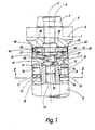
- Fig. 1 ein Spannsystem gemäß der Erfindung, teilweise im axialen Schnitt, in einer Seitenansicht,
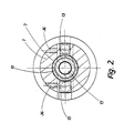
- Fig. 2 das Spannsystem nach Fig. 1, geschnitten längs der Linie II-II der Fig. 1, in einer Draufsicht,
- Fig. 3 bis 5 ein Spannelement des Spannsystems nach Fig.1, in einer stirnseitigen Seitenansicht, im axialen Schnitt, in einer Seitenansicht und in einer Draufsicht, und
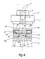
- Fig. 6 ein Spannsystem gemäß der Erfindung, in einer abgewandelten Ausführungsform, in einer Schnittdarstellung entsprechend Fig. 1.
- 1 is a clamping system according to the invention, partly in axial section, in a side view,
- 2, the clamping system of FIG. 1, cut along the line II-II of FIG. 1, in a plan view,
- 3 to 5 a tensioning element of the tensioning system according to FIG. 1, in a frontal side view, in axial section, in a side view and in a top view, and
- 6 shows a clamping system according to the invention, in a modified embodiment, in a sectional view corresponding to FIG. 1.
Das Spannsystem weist in beiden Ausführungsformen, nach Fig. 1 und 6, einen im wesentlichen zylindrischen, massiven Aufnahmekörper 1 mit einem zu der Drehachse 2 koaxialen NCT-Kegel 3 und einer koaxialen Gewindebohrung 4 auf, die von der Stirnseite des NCT-Kegels 3 her in den Aufnahmekörper 1 führt. Der NCT-Kegel 3, an den sich eine rechtwinklig zu der Drehachse 2 verlaufende Planfläche 5 anschließt, dient zur rundlaufgenauen Kupplung des Aufnahmekörpers 1 mit einer nicht weiter dargestellten Werkzeugspindel. Dieser zugeordnete Mitnehmer greifen in randoffene Ausnehmungen 6 des Werkzeugkörpers 1 ein; die axiale Verspannung kann über eine in die Gewindebohrung 3 eingeschraubte zentrale Spannschraube erfolgen.In both embodiments, according to FIGS. 1 and 6, the clamping system has an essentially cylindrical, solid
Auf der der Planfläche 5 gegenüberliegenden Seite ist in dem Aufnahekörper 1 eine koaxiale kegelige Paßbohrung 7 ausgebildet, die von einer rechtwinklig zu der Drehachse 2 verlaufenden planen Anlagefläche 8 ausgeht.On the side opposite the
Mit dem Aufnahmekörper 1 ist ein im wesentlichen zylindrisches Anschlußteil 9 verspannt, das ein nicht weiter dargestelltes rundlaufendes Werkzeug, bspw. einen Fräsmesserkopf, trägt. Das Anschlußteil 9 trägt stirnseitig einen koaxialen kegeligen Paßzapfen 10(Fig.1) oder 10a (Fig. 6), der von einer rechtwinklig zu der Drehachse 2 sich erstreckenden planen Anlagefläche 11 umgeben ist. Der Innenkegel der Paßbohrung 7 weist einen um einen vorbestimmten kleinen Winkelwert größeren Kegelwinkel als der Außenkegel des Paßzapfens 10,10a auf. Die Anordnung ist derart getroffen, daß bei der Längsverschiebung der Konuslücke zwischen den beiden Kegeln wenigstens einer dieser beiden Kegel bis zur großflächigen Anlage der beiden Kegel aneinander elastisch verformbar ist.An essentially cylindrical connecting part 9 is clamped to the
Im Bereiche der Anlagefläche 8 sind in entsprechende achsparallele zylindrische Bohrungen 12 des Aufnahmekörpers Mitnehmer 13 (Fig.1) mit einem zylindrischen Schaft 14 maßgenau eingepreßt, die in entsprechende randoffene Aussparungen 15 im Bereiche der Anlagefläche 11 des Anschlußteiles 9 eingreifen und eine drehfeste spielfreie Kupplung zwischen dem Anschlußteil 9 und dem Aufnahmekörper 1 herstellen. Diese Mitnehmer 13 sind in Fig.6 nicht weiter dargestellt.In the area of the
Bei der Ausführungsform nach Fig. 1 weist das Anschlußteil 9 im Bereiche des Paßzapfens 10 eine von dessen planer Stirnfläche 16 ausgehende koaxiale Gewindebohrung 17 auf. Auf seine Stirnfläche 16 ist ein koaxialer pilzförmiger Spannzapfen 18 spielfrei aufgesetzt, der als rotationssymmetrisches Drehteil ausgebildet ist und einen koaxialen Gewindeansatz 19 trägt, welcher in die Gewindebohrung 17 eingeschraubt ist.In the embodiment according to FIG. 1, the connecting part 9 has, in the region of the
Alternativ könnte der Spannzapfen 18 auch einstückig an dem Paßzapfen 10 angeformt sein, womit der Gewindeansatz 19 entfällt.Alternatively, the clamping pin 18 could also be integrally formed on the
Der pilzförmige Spannzapfen 18 weist anschließend an seine obere ebene Stirnfläche einen ersten zylindrischen Abschnitt 20 auf, der auf der der Stirnfläche gegenüberliegenden Seite durch eine ringsumlaufende, eine Keilfläche bildende koaxiale Kegelmantelfläche 21 begrenzt ist. Die Kegelmantelfläche 21 schließt mit der Drehachse 2 einen spitzen Winkel 22 ein; an sie schließt sich ein kegelstumpfförmiger koaxialer Abschnitt 24 an, auf den schließlich ein zweiter koaxialer zylindrischer Abschnitt 25 folgt, der mit seiner rechtwinklig zu der Drehachse 2 verlaufenden Stirnfläche stramm auf der Stirnfläche 16 des Paßzapfens 10 sitzt.The mushroom-shaped clamping pin 18 then has a first
In dem Aufnahmekörper 1 der Ausführungsform nach Fig. 1 ist anschließend an die kegelige Paßbohrung 7 ein koaxialer, im wesentlichen zylindrischer Hohlraum 25 ausgebildet, der im zusammengesetzten Zustand den Spannzapfen 18 aufnimmt. In den Hohlraum 25 führen zwei zueinander koaxiale, in den den Hohlraum 25 umgebenden Wandungsteilen des Aufnahmekörpers 1 angeordnete zylindrische Führungsbohrungen 26, deren gemeinsame Achse rechtwinklig zu der Drechachse 2 verläuft und diese schneidet. In den beiden Führungsbohrungen 26 sind zwei Spannelemente in Gestalt zylindrischer Schieber 27 längsverschieblich gelagert, von denen jeder eine durchgehende Gewindebohrung 28 aufweist. In die beiden Gewindehohrungen ist eine Summenschraube 29 eingeschraubt, die den Hohlraum 25 in dem Bereich oberhalb des Spannzapfens 18 durchquert und an einem Ende eine Betätigungseinrichtung in Gestalt eines Innensechskants oder anderen Innenprofils 30 aufweist. Die Summenschraube 29 ist somit ersichtlich von außen, d.h. genauer von der Seite des Aufnahmekörpers 1 her betätigbar.In the receiving
Wie insbesondere den Fig. 3 bis 5 zu entnehmen, ist jeder der Schieber 27 an seinem in den Hohlraum 25 ragenden Ende mit einer vorspringenden Spannase 31 ausgebildet, die auf ihrer in Fig.1 nach oben weisenden Seite eine im westentlichen kegelförmige Spannfläche 32 trägt. Die Spannfläche 32 schließt einen spitzen Winkel 33 von ca. 20° mit der Längsachse des Schiebers 27 ein. Sie ist durch eine nutenartige Vertiefung 330 unterbrochen, derart, daß sich beidseitig der nutenartigen Vertiefung 330 zwei gleichgestaltete Spannflächenbereiche ergeben. An ihrer dem Spannzapfen 18 zugewandten Stirnseite ist die Spannase 31 bei 34, dem Umriß des Spannzapfens 18 folgend, teilkreisförmig ausgespart, derart, daß sie den Spannzapfen 18 auf der Kegelmantelfläche 21 über einen Winkelbereich (Sektor) von fast 180° umgreift. In eine an dem Schieber 27 seitlich angebrachte Längsnut 35 greift jeweils eine Madenschraube 36 ein, durch die der Schieber 27 unverlierbar gehaltert ist.As can be seen in particular from FIGS. 3 to 5, each of the
Zum Spannen des Anschlußteiles 9 an dem Aufnahmekörper 1 wird bei in einer zurückgezogenen unwirksamen Stellung stehenden Schiebern 27 der Paßzapfen 10 in die Paßbohrung 7 des Aufnahmekörpers 1 eingefügt, derart, daß die im Querschnitt rechteckigen Mitnehmer 13 in die Aussparungen 15 eingreifen. Anschließend wird die Summenschraube 29 angezogen, die die beiden Schieber 27 radial aufeinander zu bewegt. Dabei untergreifen die beiden Teilbereiche der schrägen Spannfläche 32 die schräge Keil- oder Kegelmantelfläche 21 des Spannzapfens 18 in der aus Fig. 1 ersichtlichen Weise. Wegen dieser Schräglage der Flächen 21, 32 wird auf den Spannzapfen 18 über die Spannasen 31 und die Schieber 27 eine große axial wirkende Spannkraftkomponente übertragen, die bestrebt ist, den Paßzapfen 10 in die Paßbohrung 7 hineinzuziehen. Die radialen Spannkraftkomponenten der beiden einander genau 180° gegenüberliegenden Schieber 27 heben sich gegenseitig auf. Die Größe der auf den Spannzapfen 18 zur Wirkung kommenden Axialkomponente der Spannkraft hängt von der Wahl der Winkel 22, 33 ab; sie kann beliebig gewählt werden.For tensioning the connecting part 9 on the receiving
Der Spannzapfen 18 ist mit seinem zweiten zylindrischen Abschnitt 25 bei 37 (Fig. 1) an der Innenwand des zylindrischen Hohlraumes 25 längsverschieblich geführt.The clamping pin 18 is guided with its second
Die Spannfläche 32 der Schieber 27 kann auch in mehr als zwei Spannflächenbereiche unterteilt sein, wie es auch denkbar ist, an jedem der Schieber 27 mehrere getrennte Spannasen 31 vorzusehen. Die Schieber 27 selbst sind bei dem beschriebenen Ausführungsbeispiel in Gestalt zylindrischer Bolzen ausgebildet; alternativ könnten sie auch eine eckige Querschnittsgestalt aufweisen. Denkbar wäre es auch in besonderen Fällen, an dem Spannzapfen 18 mehrere radial bewegliche Spannelemente angreifen zu lassen, die einander gegenüberliegend aber jeweils so angeordnet sein müssen, daß sich keine einseitige, an dem Spannzapfen 18 angreifende radiale spannkraftkomponente ergibt.The clamping
Bei abgeschraubtem Spannzapfen 18 kann das Anschlußteil 9 in einem mit einer der Gewindebohrung 4 entsprechenden Längsbohrung ausgestatteten Aufnahmekörper 1 auch mittels der herkömmlichen zentralen Spannschraube gespannt werden, womit der Aufnahmekörper 9 universell einsetzbar ist. Die axialen Spannkräfte gewährleisten in jedem Falle eine spielfreie gegenseitige Anlage der Anlageflächen 8,11 und eine radiale Zentrierung des Anschlußteils 9 bezüglich des Aufnahmekörpers 1 über den als Zentrierzapfen wirkenden Paßzapfen 10.When the clamping pin 18 is unscrewed, the connecting part 9 can also be clamped in a receiving
Die Ausführungsform nach Fig. 6 ist ähnlich jener nach den Fig. 1 bis 5 ausgebildet. Gleiche oder entsprechende Teile sind deshalb mit gleichen Bezugszeichen versehen, wobei sich eine nochmalige Erläuterung insoweit erübrigt.The embodiment of FIG. 6 is similar to that of FIGS. 1 to 5. The same or corresponding parts are therefore provided with the same reference numerals, with no further explanation being necessary.
Abweichend von der Ausführungsform nach den Fig. 1 bis 5 ist der Paßzapfen 10a selbst unmittelbar als Spannzapfen ausgebildet, so daß ein auf die Stirnfläche 16 des Paßzapfens 10a aufgesetzter pilzförmiger Spannzapfen 18 entfällt. Zu diesem Zwecke ist der kegelstumpfförmige Paßzapfen 10a im Bereiche der Paßbohrung 7 mit einer ringsumlaufenden Nut 210 versehen, deren Boden 211 in einer rechtwinklig zu der Drehachse 2 sich erstreckenden Ebene liegt und die auf der gegenüberliegenden Seite einseitig durch die Kegelmantelfläche 21 begrenzt ist. Die Nut 210 weist eine solche Höhe in Achsrichtung sowie eine solche Tiefe auf, daß bei dem in Fig.6 veranschaulichten Spannzustand die in die Nut 210 eingreifenden Spannasen 31 der beiden zylindrischen Schieber 27,von anderen Nutenwandungsteilen unbehindert,lediglich mit ihren Spannflächen 32 an der Kegelmantelfläche 21 angreifen und die zur Verspannung erforderlichen Axialkräfte übertragen.Deviating from the embodiment according to FIGS. 1 to 5, the fitting pin 10a itself is designed directly as a clamping pin, so that a mushroom-shaped clamping pin 18 placed on the
Der Hohlraum 25 ist in diesem Falle unmittelbar durch die Paßbohrung 7 gebildet. Die Spannasen 31 sind bei 34 derart ausgebildet, daß sie den durch den Paßzapfen 10a gebildeten "Spannzapfen" im Bereiche der Wurzel der Nut 210 jeweils über fast 180° umgreifen.In this case, the
Claims (11)
Priority Applications (1)
| Application Number | Priority Date | Filing Date | Title |
|---|---|---|---|
| AT87118285T ATE96711T1 (en) | 1987-04-08 | 1987-12-10 | MULTI-PART CLAMPING SYSTEM, PARTICULARLY FOR ROTARY TOOLS. |
Applications Claiming Priority (2)
| Application Number | Priority Date | Filing Date | Title |
|---|---|---|---|
| DE3711808 | 1987-04-08 | ||
| DE19873711808 DE3711808A1 (en) | 1987-04-08 | 1987-04-08 | MULTI-PIECE CLAMPING SYSTEM, IN PARTICULAR FOR ROTARY TOOLS |
Publications (3)
| Publication Number | Publication Date |
|---|---|
| EP0285704A2 true EP0285704A2 (en) | 1988-10-12 |
| EP0285704A3 EP0285704A3 (en) | 1990-04-25 |
| EP0285704B1 EP0285704B1 (en) | 1993-11-03 |
Family
ID=6325113
Family Applications (1)
| Application Number | Title | Priority Date | Filing Date |
|---|---|---|---|
| EP87118285A Expired - Lifetime EP0285704B1 (en) | 1987-04-08 | 1987-12-10 | Clamping system of several parts in particular for concentric running tools |
Country Status (6)
| Country | Link |
|---|---|
| US (1) | US4799837A (en) |
| EP (1) | EP0285704B1 (en) |
| JP (1) | JPS63260706A (en) |
| AT (1) | ATE96711T1 (en) |
| DE (2) | DE3711808A1 (en) |
| ES (1) | ES2044904T3 (en) |
Cited By (2)
| Publication number | Priority date | Publication date | Assignee | Title |
|---|---|---|---|---|
| US6902355B2 (en) * | 2000-10-02 | 2005-06-07 | Mapal Fabrick Fur Prazisionswerkzeuge Dr. Kress Kg | Junction |
| WO2007147711A1 (en) * | 2006-06-19 | 2007-12-27 | Komet Group Holding Gmbh | Junction between two components of a rotating tool system |
Families Citing this family (7)
| Publication number | Priority date | Publication date | Assignee | Title |
|---|---|---|---|---|
| DE3904259A1 (en) * | 1989-02-13 | 1990-08-16 | Guehring Gottlieb Fa | COUPLING FOR DETACHABLE FIXING OF COMPONENTS ON CORRESPONDING CARRIER PARTS |
| DE3930245A1 (en) * | 1989-09-11 | 1991-03-14 | Otto Zettl | CLUTCH DEVICE FOR MODULAR TOOLING SYSTEMS |
| WO2000053361A1 (en) * | 1999-03-11 | 2000-09-14 | Sunspot Edm Tooling | Tool holder |
| US8087675B2 (en) * | 2006-08-24 | 2012-01-03 | Korson Daniel G | Chuck holder incorporating independent arrayed wedge clamps for clamping such as irregularly shaped and thin wall parts with a minimum of deformation |
| US8033766B2 (en) * | 2008-05-09 | 2011-10-11 | Kennametal Inc. | Tool holder with ball clamping mechanism |
| IT201700013072A1 (en) * | 2017-02-07 | 2018-08-07 | Algra S P A | DEVICE FOR LOCKING TOOL HOLDERS ON LATHES |
| IT201700052288A1 (en) * | 2017-05-15 | 2018-11-15 | Algra S P A | DEVICE FOR AUTOMATIC TOOL LOCKING ON LATHES AND MACHINES THAT CARRY OUT PROCESSING FOR CHANGING CHIPS |
Citations (8)
| Publication number | Priority date | Publication date | Assignee | Title |
|---|---|---|---|---|
| DE2606215A1 (en) * | 1976-02-17 | 1977-08-25 | Deckel Ag Friedrich | TOOL CLAMPING DEVICE |
| EP0123156A2 (en) * | 1983-04-22 | 1984-10-31 | Montanwerke Walter Gmbh | Clamping system, especially for rotating tools |
| US4575293A (en) * | 1984-07-12 | 1986-03-11 | Mario Berti | Machine tool holder having opposed ramp members |
| EP0189697A1 (en) * | 1985-01-21 | 1986-08-06 | Sandvik Tobler S.A. | Quick clamping system |
| EP0204671A2 (en) * | 1985-05-08 | 1986-12-10 | Santrade Ltd. | Tool coupling device |
| EP0219594A1 (en) * | 1985-10-23 | 1987-04-29 | Klement, Klaus-Dieter | Device actuated by fluid under pressure |
| US4729702A (en) * | 1986-10-10 | 1988-03-08 | Carboloy Inc. | Clamping means for taper tool shanks |
| EP0281760A2 (en) * | 1987-03-11 | 1988-09-14 | Firma Gottlieb Gühring | Coupling system for a cutting tool having a shaft |
Family Cites Families (11)
| Publication number | Priority date | Publication date | Assignee | Title |
|---|---|---|---|---|
| US2684249A (en) * | 1950-11-30 | 1954-07-20 | Giddings & Lewis | Toolhead and taper shank adapter |
| SE368917B (en) * | 1969-03-24 | 1974-07-29 | Bofors Ab | |
| US3618962A (en) * | 1970-02-17 | 1971-11-09 | Warner Swasey Co | Collet chuck |
| GB1557345A (en) * | 1977-02-15 | 1979-12-05 | Leitner K | Chuck |
| JPS5558939A (en) * | 1978-10-23 | 1980-05-02 | Mitsubishi Metal Corp | Quick change type tool holder |
| SE427732B (en) * | 1979-09-20 | 1983-05-02 | Sandvik Ab | tool holder |
| DE3131478A1 (en) * | 1981-08-08 | 1983-02-24 | Emil Wohlhaupter u. Co, 7443 Frickenhausen | Arrangement for connecting two tool parts rotating about a common axis |
| DE3227345A1 (en) * | 1982-07-22 | 1984-01-26 | Dieter Dipl.-Ing. 7250 Leonberg Göltenbodt | Tool holder for lathes |
| DE3237128A1 (en) * | 1982-10-07 | 1984-04-12 | Wilhelm Fette Gmbh, 2053 Schwarzenbek | COMBINATION TOOL |
| JPS6020832A (en) * | 1983-07-12 | 1985-02-02 | Fuji Seikou Kk | Holder for revolving cutting tool |
| DE3410154A1 (en) * | 1984-03-20 | 1985-10-03 | Fried. Krupp Gmbh, 4300 Essen | TOOL DEVICE WITH INTERCHANGEABLE TOOL HEAD |
-
1987
- 1987-04-08 DE DE19873711808 patent/DE3711808A1/en active Granted
- 1987-12-10 AT AT87118285T patent/ATE96711T1/en not_active IP Right Cessation
- 1987-12-10 ES ES87118285T patent/ES2044904T3/en not_active Expired - Lifetime
- 1987-12-10 DE DE87118285T patent/DE3788060D1/en not_active Expired - Lifetime
- 1987-12-10 EP EP87118285A patent/EP0285704B1/en not_active Expired - Lifetime
-
1988
- 1988-02-05 US US07/152,913 patent/US4799837A/en not_active Expired - Fee Related
- 1988-04-06 JP JP63084945A patent/JPS63260706A/en active Pending
Patent Citations (8)
| Publication number | Priority date | Publication date | Assignee | Title |
|---|---|---|---|---|
| DE2606215A1 (en) * | 1976-02-17 | 1977-08-25 | Deckel Ag Friedrich | TOOL CLAMPING DEVICE |
| EP0123156A2 (en) * | 1983-04-22 | 1984-10-31 | Montanwerke Walter Gmbh | Clamping system, especially for rotating tools |
| US4575293A (en) * | 1984-07-12 | 1986-03-11 | Mario Berti | Machine tool holder having opposed ramp members |
| EP0189697A1 (en) * | 1985-01-21 | 1986-08-06 | Sandvik Tobler S.A. | Quick clamping system |
| EP0204671A2 (en) * | 1985-05-08 | 1986-12-10 | Santrade Ltd. | Tool coupling device |
| EP0219594A1 (en) * | 1985-10-23 | 1987-04-29 | Klement, Klaus-Dieter | Device actuated by fluid under pressure |
| US4729702A (en) * | 1986-10-10 | 1988-03-08 | Carboloy Inc. | Clamping means for taper tool shanks |
| EP0281760A2 (en) * | 1987-03-11 | 1988-09-14 | Firma Gottlieb Gühring | Coupling system for a cutting tool having a shaft |
Cited By (3)
| Publication number | Priority date | Publication date | Assignee | Title |
|---|---|---|---|---|
| US6902355B2 (en) * | 2000-10-02 | 2005-06-07 | Mapal Fabrick Fur Prazisionswerkzeuge Dr. Kress Kg | Junction |
| WO2007147711A1 (en) * | 2006-06-19 | 2007-12-27 | Komet Group Holding Gmbh | Junction between two components of a rotating tool system |
| US8172490B2 (en) | 2006-06-19 | 2012-05-08 | Komet Group Gmbh | Junction between two components of a rotating tool system |
Also Published As
| Publication number | Publication date |
|---|---|
| DE3711808C2 (en) | 1990-04-26 |
| US4799837A (en) | 1989-01-24 |
| DE3788060D1 (en) | 1993-12-09 |
| EP0285704B1 (en) | 1993-11-03 |
| ES2044904T3 (en) | 1994-01-16 |
| DE3711808A1 (en) | 1988-10-20 |
| ATE96711T1 (en) | 1993-11-15 |
| EP0285704A3 (en) | 1990-04-25 |
| JPS63260706A (en) | 1988-10-27 |
Similar Documents
| Publication | Publication Date | Title |
|---|---|---|
| EP0507147B1 (en) | Coupling | |
| DE10326928B4 (en) | Interface between two sub-elements of a tool system | |
| EP0282090A1 (en) | Inserted tooth milling cutter | |
| CH656335A5 (en) | DRILLING TOOL. | |
| EP0385280A1 (en) | Inside turning tool | |
| EP1240963B1 (en) | Connecting element | |
| EP1896207B1 (en) | Tool system with interface | |
| WO1996036452A1 (en) | Profiled inserted-blade cutter | |
| DE3433878A1 (en) | AXIAL CLAMP CONNECTION | |
| EP0490913B1 (en) | Device for removably securing a tool to a machine spindle | |
| EP0299141A1 (en) | Machine tool, punching machine or suchlike machine with a tool holding device for automatic tool changing | |
| EP0285704B1 (en) | Clamping system of several parts in particular for concentric running tools | |
| EP0962280B1 (en) | Alignment device | |
| EP0193020A2 (en) | Tooling device with an exchangeable tool head | |
| DE10205635B4 (en) | connection tool | |
| EP3263251B1 (en) | Collet, clamping nut, and collet chuck having special interaction between the collet and the clamping nut | |
| DE102017131001A1 (en) | Milling tool holder and milling tool | |
| DE8517718U1 (en) | Machine tool spindle and matching tool holder | |
| EP0282786B1 (en) | Coupling device for connecting pieces rotationally | |
| DE2533495B2 (en) | Boring bar | |
| EP1896219B1 (en) | Joint | |
| DE3521799C2 (en) | ||
| DE4311109A1 (en) | Modular tool system | |
| DE3828239C2 (en) | ||
| DE3546543C2 (en) | Machine-tool spindle and matching tool holder |
Legal Events
| Date | Code | Title | Description |
|---|---|---|---|
| PUAI | Public reference made under article 153(3) epc to a published international application that has entered the european phase |
Free format text: ORIGINAL CODE: 0009012 |
|
| AK | Designated contracting states |
Kind code of ref document: A2 Designated state(s): AT BE CH DE ES FR GB IT LI LU NL SE |
|
| PUAL | Search report despatched |
Free format text: ORIGINAL CODE: 0009013 |
|
| AK | Designated contracting states |
Kind code of ref document: A3 Designated state(s): AT BE CH DE ES FR GB IT LI LU NL SE |
|
| 17P | Request for examination filed |
Effective date: 19900913 |
|
| 17Q | First examination report despatched |
Effective date: 19911216 |
|
| RAP1 | Party data changed (applicant data changed or rights of an application transferred) |
Owner name: WALTER AKTIENGESELLSCHAFT |
|
| GRAA | (expected) grant |
Free format text: ORIGINAL CODE: 0009210 |
|
| PGFP | Annual fee paid to national office [announced via postgrant information from national office to epo] |
Ref country code: LU Payment date: 19931015 Year of fee payment: 7 |
|
| PGFP | Annual fee paid to national office [announced via postgrant information from national office to epo] |
Ref country code: FR Payment date: 19931021 Year of fee payment: 7 |
|
| AK | Designated contracting states |
Kind code of ref document: B1 Designated state(s): AT BE CH DE ES FR GB IT LI LU NL SE |
|
| REF | Corresponds to: |
Ref document number: 96711 Country of ref document: AT Date of ref document: 19931115 Kind code of ref document: T |
|
| PGFP | Annual fee paid to national office [announced via postgrant information from national office to epo] |
Ref country code: GB Payment date: 19931108 Year of fee payment: 7 |
|
| ET | Fr: translation filed | ||
| REF | Corresponds to: |
Ref document number: 3788060 Country of ref document: DE Date of ref document: 19931209 |
|
| PGFP | Annual fee paid to national office [announced via postgrant information from national office to epo] |
Ref country code: BE Payment date: 19931215 Year of fee payment: 7 |
|
| EPTA | Lu: last paid annual fee | ||
| PGFP | Annual fee paid to national office [announced via postgrant information from national office to epo] |
Ref country code: SE Payment date: 19931220 Year of fee payment: 7 |
|
| PGFP | Annual fee paid to national office [announced via postgrant information from national office to epo] |
Ref country code: ES Payment date: 19931227 Year of fee payment: 7 |
|
| PGFP | Annual fee paid to national office [announced via postgrant information from national office to epo] |
Ref country code: CH Payment date: 19931228 Year of fee payment: 7 Ref country code: AT Payment date: 19931228 Year of fee payment: 7 |
|
| PGFP | Annual fee paid to national office [announced via postgrant information from national office to epo] |
Ref country code: NL Payment date: 19931231 Year of fee payment: 7 |
|
| ITF | It: translation for a ep patent filed |
Owner name: JACOBACCI CASETTA & PERANI S.P.A. |
|
| REG | Reference to a national code |
Ref country code: ES Ref legal event code: FG2A Ref document number: 2044904 Country of ref document: ES Kind code of ref document: T3 |
|
| GBT | Gb: translation of ep patent filed (gb section 77(6)(a)/1977) |
Effective date: 19940203 |
|
| PLBE | No opposition filed within time limit |
Free format text: ORIGINAL CODE: 0009261 |
|
| STAA | Information on the status of an ep patent application or granted ep patent |
Free format text: STATUS: NO OPPOSITION FILED WITHIN TIME LIMIT |
|
| 26N | No opposition filed | ||
| PG25 | Lapsed in a contracting state [announced via postgrant information from national office to epo] |
Ref country code: LU Free format text: LAPSE BECAUSE OF NON-PAYMENT OF DUE FEES Effective date: 19941210 Ref country code: GB Effective date: 19941210 Ref country code: AT Effective date: 19941210 |
|
| PG25 | Lapsed in a contracting state [announced via postgrant information from national office to epo] |
Ref country code: SE Effective date: 19941211 |
|
| PG25 | Lapsed in a contracting state [announced via postgrant information from national office to epo] |
Ref country code: LI Effective date: 19941231 Ref country code: CH Effective date: 19941231 Ref country code: BE Effective date: 19941231 |
|
| EAL | Se: european patent in force in sweden |
Ref document number: 87118285.3 |
|
| BERE | Be: lapsed |
Owner name: WALTER A.G. Effective date: 19941231 |
|
| PG25 | Lapsed in a contracting state [announced via postgrant information from national office to epo] |
Ref country code: NL Effective date: 19950701 |
|
| GBPC | Gb: european patent ceased through non-payment of renewal fee |
Effective date: 19941210 |
|
| PG25 | Lapsed in a contracting state [announced via postgrant information from national office to epo] |
Ref country code: FR Effective date: 19950831 |
|
| REG | Reference to a national code |
Ref country code: CH Ref legal event code: PL |
|
| NLV4 | Nl: lapsed or anulled due to non-payment of the annual fee |
Effective date: 19950701 |
|
| EUG | Se: european patent has lapsed |
Ref document number: 87118285.3 |
|
| REG | Reference to a national code |
Ref country code: FR Ref legal event code: ST |
|
| PG25 | Lapsed in a contracting state [announced via postgrant information from national office to epo] |
Ref country code: ES Free format text: LAPSE BECAUSE OF NON-PAYMENT OF DUE FEES Effective date: 19951211 |
|
| REG | Reference to a national code |
Ref country code: ES Ref legal event code: FD2A Effective date: 19960113 |
|
| PG25 | Lapsed in a contracting state [announced via postgrant information from national office to epo] |
Ref country code: IT Free format text: LAPSE BECAUSE OF NON-PAYMENT OF DUE FEES;WARNING: LAPSES OF ITALIAN PATENTS WITH EFFECTIVE DATE BEFORE 2007 MAY HAVE OCCURRED AT ANY TIME BEFORE 2007. THE CORRECT EFFECTIVE DATE MAY BE DIFFERENT FROM THE ONE RECORDED. Effective date: 20051210 |
|
| PGFP | Annual fee paid to national office [announced via postgrant information from national office to epo] |
Ref country code: DE Payment date: 20061231 Year of fee payment: 20 |