EP0504051B1 - Hydrokinetic coupling with fixed filling amount and principal and auxiliary retardation chambers - Google Patents
Hydrokinetic coupling with fixed filling amount and principal and auxiliary retardation chambers Download PDFInfo
- Publication number
- EP0504051B1 EP0504051B1 EP92400645A EP92400645A EP0504051B1 EP 0504051 B1 EP0504051 B1 EP 0504051B1 EP 92400645 A EP92400645 A EP 92400645A EP 92400645 A EP92400645 A EP 92400645A EP 0504051 B1 EP0504051 B1 EP 0504051B1
- Authority
- EP
- European Patent Office
- Prior art keywords
- receiving element
- chamber
- forming
- delay chamber
- auxiliary
- Prior art date
- Legal status (The legal status is an assumption and is not a legal conclusion. Google has not performed a legal analysis and makes no representation as to the accuracy of the status listed.)
- Expired - Lifetime
Links
Images

Classifications
-
- F—MECHANICAL ENGINEERING; LIGHTING; HEATING; WEAPONS; BLASTING
- F16—ENGINEERING ELEMENTS AND UNITS; GENERAL MEASURES FOR PRODUCING AND MAINTAINING EFFECTIVE FUNCTIONING OF MACHINES OR INSTALLATIONS; THERMAL INSULATION IN GENERAL
- F16D—COUPLINGS FOR TRANSMITTING ROTATION; CLUTCHES; BRAKES
- F16D33/00—Rotary fluid couplings or clutches of the hydrokinetic type
- F16D33/06—Rotary fluid couplings or clutches of the hydrokinetic type controlled by changing the amount of liquid in the working circuit
- F16D33/08—Rotary fluid couplings or clutches of the hydrokinetic type controlled by changing the amount of liquid in the working circuit by devices incorporated in the fluid coupling, with or without remote control
-
- F—MECHANICAL ENGINEERING; LIGHTING; HEATING; WEAPONS; BLASTING
- F16—ENGINEERING ELEMENTS AND UNITS; GENERAL MEASURES FOR PRODUCING AND MAINTAINING EFFECTIVE FUNCTIONING OF MACHINES OR INSTALLATIONS; THERMAL INSULATION IN GENERAL
- F16D—COUPLINGS FOR TRANSMITTING ROTATION; CLUTCHES; BRAKES
- F16D33/00—Rotary fluid couplings or clutches of the hydrokinetic type
- F16D33/06—Rotary fluid couplings or clutches of the hydrokinetic type controlled by changing the amount of liquid in the working circuit
Definitions
- the present invention relates generally to hydrokinetic couplers.
- hydrokinetic couplers generally comprise two elements, namely, a motor element, forming a pump, and a receiving element, forming a turbine, which, placed opposite in a casing, define between them a working circuit containing fluid.
- the present invention relates more particularly to the case where the "filling" of these hydrokinetic couplers is fixed, that is to say the case where their working circuit permanently contains a determined and constant quantity of fluid, fixed to the 'use.
- hydrokinetic couplers of this type find their application in particular in driving a load, by being interposed between it and the corresponding motor, and they are responsible for ensuring, first , a progressive start of the load, thus sparing the drive motor, and, then, an advantageous operating flexibility for the whole.
- the drive torque available on their output shaft depends on the filling and the speed.
- the filling is itself determined as a function, in particular, of the power to be transmitted in steady state.
- the starting drive torque may therefore be too great to effectively allow the desired progressiveness, in particular when the load to be driven has too great an inertia, as may be the case for example for certain conveyors with bandaged.
- this drive torque is then usually in a ratio of the order of 1.7 to 1.8 compared to the normal resistive torque in steady state.
- a delay chamber which, connected to the working circuit, extending annularly around the axis of the assembly, is able to limit the quantity of fluid effectively at start-up present in this working circuit, and therefore filling at this time, by a temporary bypass of a substantial part of this fluid.
- the communication between the working circuit and this delay chamber comprises, in a distinct manner, at least one sampling channel and at least one restitution channel, with, on the restitution channel, for the progressiveness sought, at least a calibrated nozzle.
- a second delay chamber hereinafter called simply for convenience, an auxiliary delay chamber.
- the sampling path connecting the working circuit to the auxiliary delay chamber involves the space separating one from the other at their outer periphery the driving element and the receiving element.
- auxiliary sampling chamber must necessarily extend at least in part radially beyond the outer peripheral diameter of the working circuit, to the detriment of the overall diametrical size of the assembly and its inertia.
- Document FR-A-2 298 037 also describes a hydrokinetic coupler, the receiving element of which, in one of its embodiments, comprises at least one bore through which a circulation of fluid takes place.
- this document FR-A-2 298 037 relates, in reality, to a coupler with variable filling, and not to a coupler with fixed filling.
- the drilling that comprises the receiving element of this coupler in this embodiment occurs near its periphery, to evacuate fluid, and not to fill the working circuit during operation.
- the present invention generally relates to an arrangement which, by taking advantage of a drilling of the receiving element, makes it possible to avoid in a very simple manner the preceding drawbacks exposed for hydrokinetic couplers with fixed filling.
- a hydrokinetic coupler with fixed filling of the type comprising, arranged opposite in a casing, two elements defining between them a working circuit containing a fluid, namely a motor element, which pump form, and a receiving element, which forms a turbine, with, connected to the working circuit to reduce the quantity of fluid which is actually present therein at start-up, two delay chambers which extend annularly around the axis of the assembly, namely, a first chamber, or main chamber, and a second chamber, or auxiliary chamber, this hydrokinetic coupler being in a way general characterized in that, the receiving element being perforated with at least one drilling, the sampling channel connecting the working circuit to the auxiliary delay chamber involves this drilling, it intervenes on half of the element receiver arranged in its mean diameter and its outer peripheral diameter, the auxiliary delay chamber itself extends between these two diameters, on the side of the receiver element, and the main delay chamber extends inside the mean diameter of the receiving element, also on the side of this receiving element.
- the drilling thus used for the sampling channel serving the auxiliary delay chamber is usually provided for pressure balancing.
- auxiliary delay chamber can thus extend entirely in an overall volume whose diameter is at most of the order of the external peripheral diameter of the working circuit, the diametral and longitudinal dimensions, of the assembly is advantageously reduced, as well as its inertia, despite the presence of two delay chambers.
- the hydrokinetic coupler with fixed filling comprises, overall, an annular casing 10, which, formed, mainly, of two shells 10A, 10B, one forming a body, the other forming a cover, duly facing one another along a transverse joint plane 11, and duly secured to each other, for example by tie rods not visible in the figures, is crossed , axially, by a hollow shaft 12, with the interposition of rolling means 13.
- This shaft 12 is intended to be locked in rotation on the input shaft of the load to be driven, not shown.
- the casing 10 Jointly, by its shell 10A forming a body, the casing 10 is intended to be locked in rotation on the output shaft of any drive motor, also not shown.
- a generally toric working circuit 15 intended to contain a fluid not shown, namely a motor element 16A, which, integral with the housing 10, forms a pump , and a receiving element 16B, which forms a turbine and of which the shaft 12 is integral.
- 17A be the blades of the driving element 16A, and 17B those of the receiving element 16B.
- the motor element 16A is integral with the shell 10A forming the body of the casing 10, its blades 17A being directly carried by the latter, coming integrally therefrom.
- the shell 18 of the receiving element 16B is usually perforated with at least one bore 19, for balancing the pressures on one and the other of its faces.
- This bore 19, which intervenes between two blades 17B, may for example be circular.
- the mean diameter DM in question being defined as being at mid-distance between the inner peripheral diameter D1 and the outer peripheral diameter D2.
- holes 19 can thus be provided on the shell 18 of the receiving element 16B, for example being more or less regularly distributed circularly.
- the hydrokinetic coupler with fixed filling further comprises, connected to the working circuit 15, in order to reduce the quantity of fluid which is actually present there at start-up, two delay chambers which extend one and the other. other annularly around the axis X of the assembly, coaxially with respect to each other, namely, on the one hand, a first chamber 20, or main chamber, which is closest to the axis X, and a second chamber 22, or auxiliary chamber, which is the furthest therefrom.
- the main delay chamber 20 is connected to the working circuit 15, on the one hand, by a sampling channel, located towards the X axis, and, on the other hand, by a restitution channel, located more outside, and involving the intervention of calibrated nozzles.
- the auxiliary delay chamber 22 is also connected to the working circuit 15 by a sampling channel 25.
- this sampling channel 25 involves one or more holes 19 of the receiving element 16B, the auxiliary delay chamber 22 itself extends between the mean diameter DM of the receiving element 16B and its diameter external device D2, on the side of the receiving element, and the main delay chamber 20 extends inside the mean diameter DM of the receiving element 16B, also on the side of this receiving element 16B.
- the auxiliary retardation chamber 22 extends outside the shell 10B forming the cover of the casing 10, and preferably opposite the hole (s) 19 of the receiver element 16B, that is to say preferably according to a diameter corresponding substantially to the diameter along which this or these holes 19 extend, this shell 10B forming a cover itself presents, for participation in the constitution of the sampling channel 25, at least one bore 26.
- the auxiliary delay chamber 22 and the main delay chamber 20 are formed between the shell 10B forming the housing cover 10 and a cover 23 externally attached thereto, for example by screws. 24.
- the hole (s) 26 of the shell 10B forming the cover therefore open directly into the auxiliary delay chamber 22.
- the auxiliary delay chamber 22 can advantageously extend, if desired, and as shown, entirely in an overall volume whose diameter is at most of the order of outer peripheral diameter of the working circuit 15, assumed to be defined, as indicated above, by the diameter external device D2 of the receiving element 16B.
- the auxiliary delay chamber 22 can extend radially slightly beyond this outer peripheral diameter D2, the essential being that it remains radially below the outer peripheral diameter D3 of the casing 10.
- auxiliary retardation chamber 22 is moreover entirely circumscribed by the main retardation chamber 20.
- its volume represents a fraction, for example between 25% and 50% , of the volume of the working circuit 15.
- the fluid used is oil.
- part of the fluid is then derived from the working circuit 15 towards the auxiliary delay chamber 22 by the sampling channel 25.
- the auxiliary delay chamber 22 fills with fluid, by withdrawing it from the working circuit 15.
- the corresponding fluid withdrawal essentially results from the movement of the vortex, and not centrifugal force.
- the working circuit 15 thus being largely lightened with fluid, the drive motor can advantageously start without excessive load, at a substantially constant torque much lower than the nominal resistive torque in steady state.
- the characteristic curve I of the drive motor is shown in thin line, representative of the drive torque developed by this, and, in solid lines, the curve II representative of the drive torque CD, which, transmitted to the receiver element 16B, is available on the output shaft 12.
- the receiving element 16B When, at a time t2, the value thereof reaches that of the nominal resistive torque CN applied to the output shaft 12, the receiving element 16B, hitherto stationary, begins to be driven in rotation, which ensures the starting of the output shaft 12, and, by this, that of the load to be driven.
- the driven load then reaches its normal speed of rotation.
- the time t2 is of the order of 10 seconds, and the time t3 of the order of 30 to 40 seconds.
- the auxiliary delay chamber 22 extends inside the shell 10B forming the cover of the casing 10, between the latter and the receiving element 16B.
- the sampling channel 25 is therefore reduced to (x) only (s) drilling (s) 19 of this receiving element 16B.
- the auxiliary delay chamber 22 results at least in part from the fact that, between the shell 10A forming the body and the shell 10B forming the cover of the casing 10, a shim 30 is interposed axially, along their joint plane 11.
- the hydrokinetic coupler with fixed filling according to the invention advantageously has no moving part.
Description
La présente invention concerne d'une manière générale les coupleurs hydrocinétiques.The present invention relates generally to hydrokinetic couplers.
Ainsi qu'on le sait, les coupleurs hydrocinétiques comportent, globalement, deux éléments, à savoir, un élément moteur, formant pompe, et un élément récepteur, formant turbine, qui, disposés en vis-à-vis dans un carter, définissent entre eux un circuit de travail contenant du fluide.As is known, hydrokinetic couplers generally comprise two elements, namely, a motor element, forming a pump, and a receiving element, forming a turbine, which, placed opposite in a casing, define between them a working circuit containing fluid.
La présente invention vise plus particulièrement le cas où le "remplissage" de ces coupleurs hydrocinétiques est fixe, c'est-à-dire le cas où leur circuit de travail contient en permanence une quantité déterminée, et constante, de fluide, fixée à l'utilisation.The present invention relates more particularly to the case where the "filling" of these hydrokinetic couplers is fixed, that is to say the case where their working circuit permanently contains a determined and constant quantity of fluid, fixed to the 'use.
Ainsi qu'on le sait, les coupleurs hydrocinétiques de ce type trouvent notamment leur application dans l'entraînement d'une charge, en étant interposés entre celle-ci et le moteur correspondant, et ils ont à charge d'assurer, d'abord, une progressivité du démarrage de la charge, en ménageant ainsi le moteur d'entraînement, et, ensuite, une avantageuse souplesse de fonctionnement pour l'ensemble.As is known, hydrokinetic couplers of this type find their application in particular in driving a load, by being interposed between it and the corresponding motor, and they are responsible for ensuring, first , a progressive start of the load, thus sparing the drive motor, and, then, an advantageous operating flexibility for the whole.
En pratique, le couple d'entraînement disponible sur leur arbre de sortie dépend du remplissage et de la vitesse.In practice, the drive torque available on their output shaft depends on the filling and the speed.
Le remplissage est lui-même déterminé en fonction, notamment, de la puissance à transmettre en régime établi.The filling is itself determined as a function, in particular, of the power to be transmitted in steady state.
Eu égard au remplissage retenu, le couple d'entraînement au démarrage peut dès lors être trop important pour permettre effectivement la progressivité souhaitée, notamment lorsque la charge à entrainer présente une inertie trop grande, comme cela peut être le cas par exemple pour certains transporteurs à bande.With regard to the filling selected, the starting drive torque may therefore be too great to effectively allow the desired progressiveness, in particular when the load to be driven has too great an inertia, as may be the case for example for certain conveyors with bandaged.
Sans autre, en effet, ce couple d'entraînement est alors usuellement dans un rapport de l'ordre de 1,7 à 1,8 par rapport au couple résistant normal en régime établi.Without other, in fact, this drive torque is then usually in a ratio of the order of 1.7 to 1.8 compared to the normal resistive torque in steady state.
Pour pallier cette difficulté, et, donc, pour améliorer la progressivité au démarrage, il est usuel de prévoir une chambre de retardement, qui, reliée au circuit de travail, en s'étendant annulairement autour de l'axe de l'ensemble, est apte à limiter au démarrage la quantité de fluide effectivement présente dans ce circuit de travail, et donc le remplissage à cet instant, par une dérivation temporaire d'une partie substantielle de ce fluide.To overcome this difficulty, and therefore to improve the progressiveness at start-up, it is usual to provide a delay chamber, which, connected to the working circuit, extending annularly around the axis of the assembly, is able to limit the quantity of fluid effectively at start-up present in this working circuit, and therefore filling at this time, by a temporary bypass of a substantial part of this fluid.
En pratique, la communication entre le circuit de travail et cette chambre de retardement comporte, de manière distincte, au moins une voie de prélèvement et au moins une voie de restitution, avec, sur la voie de restitution, pour la progressivité recherchée, au moins un ajutage calibré.In practice, the communication between the working circuit and this delay chamber comprises, in a distinct manner, at least one sampling channel and at least one restitution channel, with, on the restitution channel, for the progressiveness sought, at least a calibrated nozzle.
Ces dispositions donnent usuellement satisfaction.These provisions are usually satisfactory.
Elles permettent en effet d'abaisser à une valeur de l'ordre de 1,5 à 1,7, voire même de l'ordre de 1,3 à 1,5 lorsque la chambre de retardement mise en oeuvre est suffisamment longue à cet effet et que les ajutages calibrés de sa voie de restitution sont établis en conséquence, le rapport entre le couple d'entraînement et le couple résistant normal en régime établi.They indeed make it possible to lower to a value of the order of 1.5 to 1.7, or even of the order of 1.3 to 1.5 when the delay chamber used is sufficiently long at this effect and that the calibrated nozzles of its return path are established accordingly, the ratio between the drive torque and the normal resistive torque in steady state.
Mais, au moins dans certains cas, pour lesquels, par exemple, il est souhaitable que ce rapport soit abaissé à une valeur de l'ordre de 1,2, elles peuvent encore s'avérer insuffisantes.But, at least in certain cases, for which, for example, it is desirable that this ratio be lowered to a value of the order of 1.2, they may still prove to be insufficient.
Pour surmonter cette difficulté, il a déjà été proposé d'adjoindre à la première chambre de retardement, ou chambre de retardement principale, une deuxième chambre de retardement, dite ci-après par simple commodité chambre de retardement auxiliaire.To overcome this difficulty, it has already been proposed to add to the first delay chamber, or main delay chamber, a second delay chamber, hereinafter called simply for convenience, an auxiliary delay chamber.
C'est le cas, par exemple, dans le document DE-A-35 22 174, auquel correspond le préambule de la revendication 1.This is the case, for example, in document DE-A-35 22 174, which corresponds to the preamble of claim 1.
Mais, dans ce document, la voie de prélèvement reliant le circuit de travail à la chambre de retardement auxiliaire fait intervenir l'espace séparant l'un de l'autre à leur périphérie extérieure l'élément moteur et l'élément récepteur.However, in this document, the sampling path connecting the working circuit to the auxiliary delay chamber involves the space separating one from the other at their outer periphery the driving element and the receiving element.
Il en résulte, tout d'abord, que le prélèvement correspondant est assuré par la force centrifuge, ce qui suppose que la vitesse de rotation soit suffisante, et implique donc un certain délai.It follows, first of all, that the corresponding withdrawal is ensured by centrifugal force, which supposes that the speed of rotation is sufficient, and therefore implies a certain delay.
Il en résulte, également, que la chambre de prélèvement auxiliaire doit nécessairement au moins pour partie s'étendre radialement au-delà du diamètre périphérique extérieur du circuit de travail, au détriment de l'encombrement diamétral hors tout de l'ensemble et de son inertie.It also follows that the auxiliary sampling chamber must necessarily extend at least in part radially beyond the outer peripheral diameter of the working circuit, to the detriment of the overall diametrical size of the assembly and its inertia.
Il est connu, par ailleurs, de prévoir des perçages dans l'élément récepteur pour diverses raisons.It is known, moreover, to provide holes in the receiving element for various reasons.
C'est le cas, par exemple dans le document US-A-3 165 894, dans lequel un tel perçage, situé au voisinage de l'axe, appartient à une voie de prélèvement destinée à intervenir en cas de surcharge, et qui, par ailleurs, concerne, non pas un coupleur hydrocinétique à remplissage fixe, mais un coupleur hydrocinétique à remplissage variable, dont le fonctionnement, de ce fait, est différent.This is the case, for example in document US-A-3,165,894, in which such a drilling, located in the vicinity of the axis, belongs to a sampling channel intended to intervene in the event of overload, and which, moreover, does not concern a hydrokinetic coupler with fixed filling, but a hydrokinetic coupler with variable filling, the operation of which is therefore different.
Le document FR-A-2 298 037 décrit lui aussi un coupleur hydrocinétique dont l'élément récepteur comporte dans une de ses formes de réalisation au moins un perçage par lequel se fait une circulation de fluide.Document FR-A-2 298 037 also describes a hydrokinetic coupler, the receiving element of which, in one of its embodiments, comprises at least one bore through which a circulation of fluid takes place.
Mais, comme le document US-A-3 165 894, ce document FR-A-2 298 037 concerne, en réalité, un coupleur à remplissage variable, et non pas un coupleur à remplissage fixe.However, like document US-A-3 165 894, this document FR-A-2 298 037 relates, in reality, to a coupler with variable filling, and not to a coupler with fixed filling.
De fait, le perçage que comporte l'élément récepteur de ce coupleur dans cette forme de réalisation intervient à proximité de sa périphérie, pour évacuer du fluide, et non pas pour remplir le circuit de travail pendant le fonctionnement.In fact, the drilling that comprises the receiving element of this coupler in this embodiment occurs near its periphery, to evacuate fluid, and not to fill the working circuit during operation.
Enfin, l'axe de ce coupleur doit nécessairement être disposé verticalement en fonctionnement.Finally, the axis of this coupler must necessarily be arranged vertically in operation.
La présente invention a d'une manière générale pour objet une disposition qui, en tirant parti d'un perçage de l'élément récepteur, permet d'éviter de manière très simple les inconvénients précédents exposés pour les coupleurs hydrocinétiques à remplissage fixe.The present invention generally relates to an arrangement which, by taking advantage of a drilling of the receiving element, makes it possible to avoid in a very simple manner the preceding drawbacks exposed for hydrokinetic couplers with fixed filling.
De manière plus précise, elle a pour objet un coupleur hydrocinétique à remplissage fixe du genre comportant, disposés en vis-à-vis dans un carter, deux éléments définissant entre eux un circuit de travail contenant un fluide, à savoir un élément moteur, qui forme pompe, et un élément récepteur, qui forme turbine, avec, reliées au circuit de travail pour y diminuer la quantité de fluide qui y est effectivement présente au démarrage, deux chambres de retardement qui s'étendent annulairement autour de l'axe de l'ensemble, à savoir, une première chambre, ou chambre principale, et une deuxième chambre, ou chambre auxiliaire, ce coupleur hydrocinétique étant d'une manière générale caractérisé en ce que, l'élément récepteur étant ajouré d'au moins un perçage, la voie de prélèvement reliant le circuit de travail à la chambre de retardement auxiliaire fait intervenir ce perçage, celui-ci intervient sur la moitié de l'élément récepteur disposé en son diamètre moyen et son diamètre périphérique extérieur, la chambre de retardement auxiliaire s'étend elle-même entre ces deux diamètres, du côté de l'élément récepteur, et la chambre de retardement principale s'étend à l'intérieur du diamètre moyen de l'élément récepteur, également du côté de cet élément récepteur.More specifically, it relates to a hydrokinetic coupler with fixed filling of the type comprising, arranged opposite in a casing, two elements defining between them a working circuit containing a fluid, namely a motor element, which pump form, and a receiving element, which forms a turbine, with, connected to the working circuit to reduce the quantity of fluid which is actually present therein at start-up, two delay chambers which extend annularly around the axis of the assembly, namely, a first chamber, or main chamber, and a second chamber, or auxiliary chamber, this hydrokinetic coupler being in a way general characterized in that, the receiving element being perforated with at least one drilling, the sampling channel connecting the working circuit to the auxiliary delay chamber involves this drilling, it intervenes on half of the element receiver arranged in its mean diameter and its outer peripheral diameter, the auxiliary delay chamber itself extends between these two diameters, on the side of the receiver element, and the main delay chamber extends inside the mean diameter of the receiving element, also on the side of this receiving element.
En pratique, le perçage ainsi mis à profit pour la voie de prélèvement desservant la chambre de retardement auxiliaire est usuellement prévu pour l'équilibrage des pressions.In practice, the drilling thus used for the sampling channel serving the auxiliary delay chamber is usually provided for pressure balancing.
Quoi qu'il en soit, ce perçage intervenant, de manière intermédiaire, entre le diamètre périphérique intérieur de l'élément récepteur, et donc du circuit de travail, et le diamètre périphérique extérieur de celui-ci, le prélèvement de fluide dans le circuit de travail en direction de la chambre de retardement auxiliaire résulte bien plus, suivant l'invention, du mouvement de vortex se développant en service dans le circuit de travail que de la force centrifuge.Anyway, this drilling intervening, in an intermediate manner, between the internal peripheral diameter of the receiving element, and therefore of the working circuit, and the external peripheral diameter of the latter, the withdrawal of fluid in the circuit of work towards the auxiliary delay chamber results much more, according to the invention, from the vortex movement developing in service in the work circuit than from centrifugal force.
Ce prélèvement peut ainsi intervenir avantageusement plus rapidement.This withdrawal can thus take place advantageously more quickly.
En effet, la vitesse linéaire du mouvement de vortex est alors maximale, en étant alors fréquemment de l'ordre de 50 m/sec.Indeed, the linear speed of the vortex movement is then maximum, being then frequently of the order of 50 m / sec.
En outre, du fait que la chambre de retardement auxiliaire peut ainsi s'étendre tout entière dans un volume hors tout dont le diamètre est au plus de l'ordre du diamètre périphérique extérieur du circuit de travail, l'encombrement diamétral, et longitudinal, de l'ensemble se trouve avantageusement réduit, ainsi que son inertie, malgré la présence de deux chambres de retardement.In addition, because the auxiliary delay chamber can thus extend entirely in an overall volume whose diameter is at most of the order of the external peripheral diameter of the working circuit, the diametral and longitudinal dimensions, of the assembly is advantageously reduced, as well as its inertia, despite the presence of two delay chambers.
Les caractéristiques et avantages de l'invention ressortiront d'ailleurs de la description qui va suivre, à titre d'exemple, en référence aux dessins schématiques annexés sur lesquels :
- la figure 1 est une demi-vue en coupe axiale d'un coupleur hydrocinétique suivant l'invention ;
- la figure 2 est un diagramme illustrant son fonctionnement ;
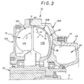
- la figure 3 est une demi-vue en coupe axiale analogue à celle de la figure 1 pour une variante de réalisation.
- Figure 1 is a half view in axial section of a hydrokinetic coupler according to the invention;
- Figure 2 is a diagram illustrating its operation;
- Figure 3 is a half view in axial section similar to that of Figure 1 for an alternative embodiment.
Tel qu'illustré sur ces figures, et de manière connue en soi, le coupleur hydrocinétique à remplissage fixe suivant l'invention comporte, globalement, un carter annulaire 10, qui, formé, principalement, de deux coquilles 10A, 10B, l'une formant corps, l'autre formant couvercle, dûment affrontées l'une à l'autre suivant un plan de joint 11 transversal, et dûment solidarisées l'une à l'autre, par exemple par des tirants non visibles sur les figures, est traversé, axialement, par un arbre 12 creux, avec interposition de moyens de roulement 13.As illustrated in these figures, and in a manner known per se, the hydrokinetic coupler with fixed filling according to the invention comprises, overall, an
Cet arbre 12 est destiné à être calé en rotation sur l'arbre d'entrée de la charge à entraîner, non représenté.This
Il forme donc l'arbre de sortie de l'ensemble.It therefore forms the output shaft of the assembly.
Conjointement, par sa coquille 10A formant corps, le carter 10 est destiné à être calé en rotation sur l'arbre de sortie d'un quelconque moteur d'entraînement, également non représenté.Jointly, by its
Il s'agit le plus souvent, en pratique, d'un moteur électrique.It is most often, in practice, an electric motor.
Dans le carter 10 sont disposés, en vis-à-vis, deux éléments définissant entre eux un circuit de travail 15 globalement torique destiné à contenir un fluide non représenté, à savoir un élément moteur 16A, qui, solidaire du carter 10, forme pompe, et un élément récepteur 16B, qui forme turbine et dont est solidaire l'arbre 12.In the
Il s'agit, dans l'un et l'autre cas, de roues à aubes à fond largement arrondi.In both cases, these are impellers with a widely rounded bottom.
Soit 17A les aubes de l'élément moteur 16A, et 17B celles de l'élément récepteur 16B.Let 17A be the blades of the
En pratique, l'élément moteur 16A fait corps avec la coquille 10A formant corps du carter 10, ses aubes 17A étant directement portées par cette dernière, en venant de manière intégrante de celle-ci.In practice, the
Il n'en est bien évidemment pas de même pour l'élément récepteur 16B, qui, à l'intérieur de la coquille 10B formant couvercle du carter 10, présente au contraire une coquille 18 spécifique pour le support de ses aubes 17B.It is obviously not the same for the
Entre son diamètre périphérique intérieur D1, d'une part, et son diamètre périphérique extérieur D2, qui définit le diamètre périphérique extérieur du circuit de travail 15, d'autre part, la coquille 18 de l'élément récepteur 16B est usuellement ajourée d'au moins un perçage 19, pour l'équilibrage des pressions sur l'une et l'autre de ses faces.Between its internal peripheral diameter D1, on the one hand, and its external peripheral diameter D2, which defines the external peripheral diameter of the
Le contour de ce perçage 19, qui intervient entre deux aubes 17B, peut par exemple être circulaire.The outline of this
Mais, en variante, il peut tout aussi bien être plus ou moins allongé en boutonnière, suivant un parallèle ou suivant un méridien.However, as a variant, it may just as well be more or less elongated in a buttonhole, along a parallel or along a meridian.
En pratique, et tel que représenté, il intervient sur la moitié de la coquille 18 de l'élément récepteur 16B disposée entre son diamètre moyen DM et son diamètre périphérique extérieur D2, le diamètre moyen DM en question étant défini comme étant à mi-distance entre le diamètre périphérique intérieur D1 et le diamètre périphérique extérieur D2.In practice, and as shown, it acts on half of the
Bien entendu, plusieurs perçages 19 peuvent être ainsi prévus sur la coquille 18 de l'élément récepteur 16B, en étant par exemple plus ou moins régulièrement répartis circulairement.Of course,
Le coupleur hydrocinétique à remplissage fixe suivant l'invention comporte, en outre, reliées au circuit de travail 15, pour y diminuer la quantité de fluide qui y est effectivement présente au démarrage, deux chambres de retardement qui s'étendent l'une et l'autre annulairement autour de l'axe X de l'ensemble, coaxialement l'une par rapport à l'autre, à savoir, d'une part, une première chambre 20, ou chambre principale, qui est la plus proche de l'axe X, et une deuxième chambre 22, ou chambre auxiliaire, qui est la plus éloignée de celui-ci.The hydrokinetic coupler with fixed filling according to the invention further comprises, connected to the
Suivant des modalités qui sont bien connues par elles-mêmes, et qui, ne relevant pas de la présente invention, ne seront pas décrites ici, la chambre de retardement principale 20 est reliée au circuit de travail 15, d'une part, par une voie de prélèvement, située vers l'axe X, et, d'autre part, par une voie de restitution, située plus à l'extérieur, et impliquant l'intervention d'ajutages calibrés.According to methods which are well known in themselves, and which, not pertaining to the present invention, will not be described here, the
De manière connue en soi, la chambre de retardement auxiliaire 22 est elle aussi reliée au circuit de travail 15 par une voie de prélèvement 25.In a manner known per se, the
Suivant l'invention, cette voie de prélèvement 25 fait intervenir le ou les perçages 19 de l'élément récepteur 16B, la chambre de retardement auxiliaire 22 s'étend elle-même entre le diamètre moyen DM de l'élément récepteur 16B et son diamètre périphérique extérieur D2, du côté de l'élément récepteur, et la chambre de retardement principale 20 s'étend à l'intérieur du diamètre moyen DM de l'élément récepteur 16B, également du côté de cet élément récepteur 16B.According to the invention, this
Dans la forme de réalisation plus particulièrement représentée sur la figure 1, la chambre de retardement auxiliaire 22 s'étend à l'extérieur de la coquille 10B formant couvercle du carter 10, et, de préférence, en regard du ou des perçages 19 de l'élément récepteur 16B, c'est-à-dire de préférence suivant un diamètre correspondant sensiblement au diamètre suivant lequel s'étendent ce ou ces perçages 19, cette coquille 10B formant couvercle présente, elle-même, pour participation à la constitution de la voie de prélèvement 25, au moins un perçage 26.In the embodiment more particularly shown in FIG. 1, the
En pratique, dans cette forme de réalisation, la chambre de retardement auxiliaire 22 et la chambre de retardement principale 20, sont formées entre la coquille 10B formant couvercle du carter 10 et un capot 23 rapporté extérieurement sur celle-ci, par exemple par des vis 24.In practice, in this embodiment, the
Le ou les perçages 26 de la coquille 10B formant couvercle débouchent donc directement dans la chambre de retardement auxiliaire 22.The hole (s) 26 of the
Compte tenu de l'implantation des perçages 19 et 26, la chambre de retardement auxiliaire 22 peut avantageusement s'étendre, si désiré, et tel que représenté, tout entière dans un volume hors tout dont le diamètre est au plus de l'ordre du diamètre périphérique extérieur du circuit de travail 15, supposé défini, comme indiqué ci-dessus, par le diamètre périphérique extérieur D2 de l'élément récepteur 16B.Given the location of the
En réalité, et c'est dans ce sens que doit être interprétée l'expression "de l'ordre de", la chambre de retardement auxiliaire 22 peut s'étendre radialement légèrement au-delà de ce diamètre périphérique extérieur D2, l'essentiel étant qu'elle reste radialement en-deçà du diamètre périphérique extérieur D3 du carter 10.In reality, and it is in this sense that the expression "of the order of" must be interpreted, the
Elle peut ainsi avantageusement équiper un carter 10 de type standard, sans modification des cotes d'encombrement diamètral de celui-ci.It can thus advantageously equip a
Dans la forme de réalisation représentée sur la figure 1, la chambre de retardement auxiliaire 22 est par ailleurs tout entière circoncrite à la chambre de retardement principale 20.In the embodiment shown in FIG. 1, the
Préférentiellement, son volume représente une fraction, comprise par exemple entre 25 % et 50 %, du volume du circuit de travail 15.Preferably, its volume represents a fraction, for example between 25% and 50% , of the volume of the working
Préférentiellement, enfin, le fluide mis en oeuvre est de l'huile.Preferably, finally, the fluid used is oil.
Quoi qu'il en soit, lorsque, lors d'une phase de démarrage, l'élément moteur 16A, dûment entraîné par le moteur d'entraînement associé, entre en rotation, le fluide présent dans le circuit de travail 15 est projeté par la force centrifuge à la partie périphérique de celui-ci.Anyway, when, during a starting phase, the
Du fait de la forme arrondie du fond des éléments moteur 16A et récepteur 16B constituant ce circuit de travail 15, il se développe, conjointement, dans celui-ci, un mouvement de vortex, schématisé par des flèches F sur la figure 1.Due to the rounded shape of the bottom of the
Grâce à ce mouvement de vortex, et tel que schématisé par la flèche F' sur la figure 1, une partie du fluide se trouve alors dérivée du circuit de travail 15 vers la chambre de retardement auxiliaire 22 par la voie de prélèvement 25.Thanks to this vortex movement, and as shown schematically by the arrow F 'in FIG. 1, part of the fluid is then derived from the working
Ainsi, comme la chambre de retardement principale 20, la chambre de retardement auxiliaire 22 se remplit de fluide, en soustrayant celui-ci au circuit de travail 15.Thus, like the
Mais, suivant l'invention, le prélèvement de fluide correspondant résulte pour l'essentiel du mouvement de vortex, et non de la force centrifuge.But, according to the invention, the corresponding fluid withdrawal essentially results from the movement of the vortex, and not centrifugal force.
Il intervient donc beaucoup plus rapidement et plus sûrement.It therefore intervenes much faster and more surely.
Le circuit de travail 15 étant ainsi largement allégé de fluide, le moteur d'entraînement peut avantageusement démarrer sans charge excessive, à un couple sensiblement constant largement inférieur au couple résistant nominal en régime établi.The working
Sur le diagramme de la figure 2, sur lequel sont reportés, en abscisses le temps t, et en ordonnées les couples C, figurent, en trait fin, la courbe caractéristique I du moteur d'entraînement, représentative du couple d'entraînement développé par celui-ci, et, en trait appuyé, la courbe II représentative du couple d'entraînement CD, qui, transmis à l'élément récepteur 16B, est disponible sur l'arbre de sortie 12.In the diagram of FIG. 2, on which the time t is plotted on the abscissa and the couples C on the ordinate, the characteristic curve I of the drive motor is shown in thin line, representative of the drive torque developed by this, and, in solid lines, the curve II representative of the drive torque CD, which, transmitted to the
Au bout d'un temps t1, qui est par exemple de l'ordre de 5 secondes, et pour lequel la courbe I recoupe la courbe II, il y a accrochage du moteur d'entraînement.At the end of a time t1, which is for example of the order of 5 seconds, and for which the curve I intersects the curve II, there is a latching of the drive motor.
La vitesse de rotation augmentant, et donc également la force centrifuge, le fluide initialement piégé par la chambre de retardement principale 20 regagne progressivement le circuit de travail 15.As the speed of rotation increases, and therefore also the centrifugal force, the fluid initially trapped by the
Il y a donc progressivement une augmentation du couple d'entraînement CD.There is therefore gradually an increase in the drive torque CD.
Lorsque, à un temps t2, la valeur de celui-ci atteint celle du couple résistant nominal CN appliqué à l'arbre de sortie 12, l'élément récepteur 16B, jusque-là immobile, commence à être entraîné en rotation, ce qui assure le démarrage de l'arbre de sortie 12, et, par celui-ci, celui de la charge à entraîner.When, at a time t2, the value thereof reaches that of the nominal resistive torque CN applied to the
Il y a ensuite une accélération de cette charge jusqu'à ce que, après être passée par un maximum, la valeur du couple d'entraînement CD soit, à un temps t3, à nouveau égale à celle du couple résistant nominal CN.There is then an acceleration of this load until, after passing through a maximum, the value of the driving torque CD is, at a time t3, again equal to that of the nominal resistive torque CN.
La charge entraînée atteint alors sa vitesse de rotation normale.The driven load then reaches its normal speed of rotation.
Par exemple, le temps t2 est de l'ordre de 10 secondes, et le temps t3 de l'ordre de 30 à 40 secondes.For example, the time t2 is of the order of 10 seconds, and the time t3 of the order of 30 to 40 seconds.
En cas de démarrage à vide, le couple résistant nominal C'N est beaucoup plus faible, et donc également le temps t'2 correspondant.In the event of an empty start, the nominal resistive torque C'N is much lower, and therefore also the corresponding time t'2.
Dans la variante de réalisation représentée sur la figure 3, la chambre de retardement auxiliaire 22 s'étend à l'intérieur de la coquille 10B formant couvercle du carter 10, entre celle-ci et l'élément récepteur 16B.In the alternative embodiment shown in FIG. 3, the
La voie de prélèvement 25 se trouve donc réduite au(x) seul(s) perçage(s) 19 de cet élément récepteur 16B.The
Par exemple, la chambre de retardement auxiliaire 22 résulte au moins pour partie de ce que, entre la coquille 10A formant corps et la coquille 10B formant couvercle du carter 10, est interposée, axialement, suivant leur plan de joint 11, une cale 30.For example, the
Mais elle peut également résulter au moins pour partie d'un affouillement interne de la coquille 10B formant couvercle.But it can also result at least in part from an internal scour of the
Quoi qu'il en soit, le fonctionnement est le même que le précédent.Anyway, the operation is the same as the previous one.
Dans tous les cas, ainsi qu'on le notera, le coupleur hydrocinétique à remplissage fixe suivant l'invention ne présente avantageusement aucune pièce en mouvement.In all cases, as will be noted, the hydrokinetic coupler with fixed filling according to the invention advantageously has no moving part.
Sa réalisation peut donc avantageusement être relativement rustique.Its realization can therefore advantageously be relatively rustic.
La présente invention ne se limite d'ailleurs pas aux formes de réalisation décrites et représentées, mais englobe toute variante d'exécution et/ou de combinaison de leurs divers éléments selon les revendications suivantes.The present invention is moreover not limited to the embodiments described and shown, but encompasses any variant embodiment and / or combination of their various elements according to the following claims.
Claims (6)
- A fluid coupling with a fixed filling capacity of the kind comprising, in facing relationship in a casing (10), two elements which define between the a working circuit (15) containing a fluid, namely a drive element (16A) which forms a pump and a receiving element (16B) which forms a turbine, with, connected to the working circuit (15) to reduce therein the amount of fluid which is effectively present therein on starting up, two delay chambers which extend annularly around the axis (X) of the assembly, namely a first chamber (20) or main chamber and a second chamber (22) or auxiliary chamber, characterised in that, the receiving element (16B) being apertured with at least one hole (19), the take-off passage (25) connecting the working circuit (15) to the auxiliary delay chamber (22) involves said hole (19), the latter occurs over the half of the receiving element (16B) which is disposed between its mean diameter (DM) and its outside peripheral diameter (D2), the auxiliary delay chamber (22) itself extends between said two diameters (DM, D2), on the side of the receiving element (16B), and the main delay chamber (20) extends on the inside of the mean diameter (DM) of the receiving element (16B), also on the side of said receiving element (16B).
- A fluid coupling with a fixed filling capacity according to claim 1 characterised in that the volume of the auxiliary delay chamber (22) represents a fraction which for example is between 25 and 50% of the volume of the working circuit (15).
- A fluid coupling with a fixed filling capacity according to either one of claims 1 and 2 characterised in that, the casing (10) comprising two shell portions (10A, 10B), one forming a body with which the drive element (16A) is fixed and the other forming a cover, the auxiliary delay chamber (22) extends on the outside of the shell portion (10B) forming the cover and preferably, facing the hole (19) in the receiving element (16B), the shell portion (10B) itself has at least one hole (26).
- A fluid coupling with a fixed filling capacity according to claim 3 characterised in that the main delay chamber (20) and the auxiliary delay chamber (22) are formed between the shell portion (10B) forming the cover and a cap (23) fitted to the latter.
- A fluid coupling with a fixed filling capacity according to either one of claims 1 and 2 characterised in that, the casing (10) comprising two shell portions (10A, 10B), one forming a body with which the drive element (16A) is fixed and the other forming a cover, the auxiliary delay chamber (22) extends on the inside of the shell portion (10B) forming the cover, between said shell portion and the receiving element (16B).
- A fluid coupling with a fixed filling capacity according to claim 5 characterised in that the auxiliary delay chamber (22) is provided at least in part by the axial interposition of a shim (30) between the shell portion (10A) forming the body and the shell portion (10B) forming the cover.
Applications Claiming Priority (2)
| Application Number | Priority Date | Filing Date | Title |
|---|---|---|---|
| FR9103031 | 1991-03-13 | ||
| FR9103031A FR2673987B1 (en) | 1991-03-13 | 1991-03-13 | HYDROKINETIC COUPLER WITH FIXED FILLING AND MAIN AND AUXILIARY DELAY CHAMBERS. |
Publications (2)
| Publication Number | Publication Date |
|---|---|
| EP0504051A1 EP0504051A1 (en) | 1992-09-16 |
| EP0504051B1 true EP0504051B1 (en) | 1995-06-14 |
Family
ID=9410686
Family Applications (1)
| Application Number | Title | Priority Date | Filing Date |
|---|---|---|---|
| EP92400645A Expired - Lifetime EP0504051B1 (en) | 1991-03-13 | 1992-03-12 | Hydrokinetic coupling with fixed filling amount and principal and auxiliary retardation chambers |
Country Status (4)
| Country | Link |
|---|---|
| US (1) | US5251441A (en) |
| EP (1) | EP0504051B1 (en) |
| DE (1) | DE69202892T2 (en) |
| FR (1) | FR2673987B1 (en) |
Families Citing this family (10)
| Publication number | Priority date | Publication date | Assignee | Title |
|---|---|---|---|---|
| DE19614591A1 (en) * | 1996-04-12 | 1996-09-26 | Voith Turbo Kg | Hydrodynamic coupling for motors or belts etc. |
| US5954746A (en) | 1997-10-09 | 1999-09-21 | Ethicon Endo-Surgery, Inc. | Dual cam trigger for a surgical instrument |
| EP0972910B1 (en) * | 1998-07-14 | 2003-06-11 | ALSTOM (Switzerland) Ltd | Non-contact sealing of gaps in gas turbines |
| DE19859428A1 (en) * | 1998-12-22 | 2000-07-06 | Voith Turbo Kg | Hydrodynamic clutch |
| DE10115561A1 (en) * | 2001-03-28 | 2002-10-24 | Voith Turbo Kg | Hydrodynamic clutch |
| US6769248B2 (en) * | 2002-06-13 | 2004-08-03 | Turbo Research, Inc. | Fluid coupling for mobile equipment |
| DE10361440B4 (en) * | 2003-12-23 | 2015-08-06 | Voith Turbo Gmbh & Co. Kg | Hydrodynamic fluid machine with closure with thermal safety function |
| DE102004059833A1 (en) * | 2004-12-10 | 2006-06-14 | Voith Turbo Gmbh & Co. Kg | Method for controlling the maximum speed of a work machine and hydrodynamic coupling therefor |
| DE102008031905A1 (en) * | 2008-07-08 | 2010-01-14 | Voith Patent Gmbh | Closure with thermal safety function for a hydrodynamic machine |
| DE102010004835A1 (en) * | 2010-01-15 | 2011-07-21 | Voith Patent GmbH, 89522 | Hydrodynamic machine and method for minimizing the drag power of such |
Citations (1)
| Publication number | Priority date | Publication date | Assignee | Title |
|---|---|---|---|---|
| US3165894A (en) * | 1962-08-13 | 1965-01-19 | American Radiator & Standard | Torque limiting ports-fluid drives |
Family Cites Families (11)
| Publication number | Priority date | Publication date | Assignee | Title |
|---|---|---|---|---|
| US2133029A (en) * | 1936-02-20 | 1938-10-11 | American Voith Contact Co | Turbo coupling |
| US2245684A (en) * | 1938-07-28 | 1941-06-17 | Deschimag | Hydraulic coupling |
| US2423812A (en) * | 1939-04-29 | 1947-07-08 | American Voith Contact Co | Thermostatic outlet valve control for fluid coupling |
| FR1225225A (en) * | 1958-05-09 | 1960-06-29 | American Radiator & Standard | Hydraulic coupling |
| US2987887A (en) * | 1958-08-14 | 1961-06-13 | Gen Motors Corp | Hydraulic coupling with fluid content control |
| FR1416023A (en) * | 1964-11-10 | 1965-10-29 | Voith Turbo K G | Hydraulic coupling, especially for electric motor transmission |
| CH600191A5 (en) * | 1975-01-17 | 1978-06-15 | Voith Turbo Kg | |
| JPS57129931A (en) * | 1981-02-02 | 1982-08-12 | Hitachi Ltd | Controller for rotational frequency of rotary machine |
| DE3318462C2 (en) * | 1983-05-20 | 1986-10-09 | Bergwerksverband Gmbh, 4300 Essen | Hydrodynamic coupling |
| DE3522174C1 (en) * | 1985-06-21 | 1986-05-22 | Voith-Turbo Gmbh & Co Kg, 7180 Crailsheim | Hydrodynamic clutch |
| FR2618865B1 (en) * | 1987-07-29 | 1991-07-05 | Valeo | TORQUE DAMPING DEVICE |
-
1991
- 1991-03-13 FR FR9103031A patent/FR2673987B1/en not_active Expired - Lifetime
-
1992
- 1992-02-18 US US07/836,542 patent/US5251441A/en not_active Expired - Lifetime
- 1992-03-12 DE DE69202892T patent/DE69202892T2/en not_active Expired - Lifetime
- 1992-03-12 EP EP92400645A patent/EP0504051B1/en not_active Expired - Lifetime
Patent Citations (1)
| Publication number | Priority date | Publication date | Assignee | Title |
|---|---|---|---|---|
| US3165894A (en) * | 1962-08-13 | 1965-01-19 | American Radiator & Standard | Torque limiting ports-fluid drives |
Also Published As
| Publication number | Publication date |
|---|---|
| US5251441A (en) | 1993-10-12 |
| FR2673987B1 (en) | 1995-09-22 |
| FR2673987A1 (en) | 1992-09-18 |
| DE69202892T2 (en) | 1995-11-23 |
| DE69202892D1 (en) | 1995-07-20 |
| EP0504051A1 (en) | 1992-09-16 |
Similar Documents
| Publication | Publication Date | Title |
|---|---|---|
| EP0504051B1 (en) | Hydrokinetic coupling with fixed filling amount and principal and auxiliary retardation chambers | |
| EP1653053A2 (en) | Two stiffness device for assembling a bearing on the shaft of a rotary engine | |
| FR2716311A1 (en) | Drive disconnection device for an oil cooled electric generator. | |
| FR2651547A1 (en) | CLUTCH WITH ELASTICITY IN THE DIRECTION OF ROTATION. | |
| WO2002044538A2 (en) | Device for centring a tube in a turbine shaft | |
| EP0036216B1 (en) | Hydrodynamic torque converter with lock-up device | |
| FR2525312A1 (en) | HYDRAULIC COUPLING AND LOCKING CLUTCH TRANSMISSION, IN PARTICULAR FOR A MOTOR VEHICLE | |
| WO2002038980A1 (en) | Torsional vibration damping device for motor vehicle clutch | |
| FR2726949A1 (en) | CHARGE GENERATOR FOR VEHICLE | |
| FR2531762A1 (en) | TORSION DAMPER DEVICE, IN PARTICULAR A CLUTCH FRICTION FOR A MOTOR VEHICLE | |
| EP1478845A1 (en) | Electric starter with a damping stop for the starter drive assembly | |
| FR2653843A1 (en) | HYDROKINETIC COUPLER WITH IMPROVED TORQUE LIMITATION AT STARTING AND ADJUSTABLE SUPERCOUPLE TO SLOW DOWN. | |
| FR2676521A1 (en) | Hydrokinetic coupling (clutch) with fixed filling and retard chamber within the working circuit | |
| FR2762371A1 (en) | TORSION OSCILLATION DAMPER WITH A TRANSMISSION ELEMENT | |
| FR2778439A1 (en) | TORSIONAL OSCILLATION SHOCK ABSORBER COMPRISING A SHOCK ABSORBER ELEMENT LOCATED ON THE SIDE OF THE DRIVE | |
| WO2000066991A1 (en) | Charging machine for heat engine test stand | |
| FR2517775A1 (en) | TEMPERATURE-CONTROLLED HYDRAULIC CLUTCH DEVICE | |
| FR2742828A1 (en) | VISCOUS FAN COUPLING, WITH FILLING RESERVE CHAMBER FUNCTION OF CENTRIFUGAL FORCE | |
| EP0015167B1 (en) | Improvement relating to automobile alternators | |
| FR2621963A1 (en) | ROTARY ELASTIC COUPLING | |
| EP1609234B1 (en) | Electromagnetic retarder for a vehicle | |
| FR2547384A1 (en) | TORQUE CONVERTER HAVING A LOCKING CONTROL DEVICE | |
| FR2725146A1 (en) | METHOD FOR MAKING A SERIOUS CONNECTION BETWEEN AN INSERT AND A TUBULAR PIECE | |
| FR2778446A1 (en) | INSTALLATION FOR MODIFYING THE FREE PASSAGE SECTION OF A CHANNEL-LIKE ELEMENT AND METHOD FOR THE PRODUCTION THEREOF | |
| FR3076334B1 (en) | CLUTCH PULLEY ASSEMBLY WITH IMPROVED IMPACT LIMITING |
Legal Events
| Date | Code | Title | Description |
|---|---|---|---|
| PUAI | Public reference made under article 153(3) epc to a published international application that has entered the european phase |
Free format text: ORIGINAL CODE: 0009012 |
|
| AK | Designated contracting states |
Kind code of ref document: A1 Designated state(s): BE DE FR GB IT |
|
| 17P | Request for examination filed |
Effective date: 19921009 |
|
| 17Q | First examination report despatched |
Effective date: 19931018 |
|
| GRAA | (expected) grant |
Free format text: ORIGINAL CODE: 0009210 |
|
| AK | Designated contracting states |
Kind code of ref document: B1 Designated state(s): BE DE FR GB IT |
|
| GBT | Gb: translation of ep patent filed (gb section 77(6)(a)/1977) |
Effective date: 19950612 |
|
| REF | Corresponds to: |
Ref document number: 69202892 Country of ref document: DE Date of ref document: 19950720 |
|
| ITF | It: translation for a ep patent filed |
Owner name: FUMERO BREVETTI S.N.C. |
|
| PLBE | No opposition filed within time limit |
Free format text: ORIGINAL CODE: 0009261 |
|
| STAA | Information on the status of an ep patent application or granted ep patent |
Free format text: STATUS: NO OPPOSITION FILED WITHIN TIME LIMIT |
|
| 26N | No opposition filed | ||
| REG | Reference to a national code |
Ref country code: GB Ref legal event code: IF02 |
|
| PGFP | Annual fee paid to national office [announced via postgrant information from national office to epo] |
Ref country code: IT Payment date: 20110322 Year of fee payment: 20 Ref country code: FR Payment date: 20110401 Year of fee payment: 20 |
|
| PGFP | Annual fee paid to national office [announced via postgrant information from national office to epo] |
Ref country code: DE Payment date: 20110411 Year of fee payment: 20 Ref country code: BE Payment date: 20110328 Year of fee payment: 20 Ref country code: GB Payment date: 20110324 Year of fee payment: 20 |
|
| REG | Reference to a national code |
Ref country code: DE Ref legal event code: R071 Ref document number: 69202892 Country of ref document: DE |
|
| REG | Reference to a national code |
Ref country code: DE Ref legal event code: R071 Ref document number: 69202892 Country of ref document: DE |
|
| BE20 | Be: patent expired |
Owner name: *SIME INDUSTRIE Effective date: 20120312 |
|
| REG | Reference to a national code |
Ref country code: GB Ref legal event code: PE20 Expiry date: 20120311 |
|
| PG25 | Lapsed in a contracting state [announced via postgrant information from national office to epo] |
Ref country code: DE Free format text: LAPSE BECAUSE OF EXPIRATION OF PROTECTION Effective date: 20120313 |
|
| PG25 | Lapsed in a contracting state [announced via postgrant information from national office to epo] |
Ref country code: GB Free format text: LAPSE BECAUSE OF EXPIRATION OF PROTECTION Effective date: 20120311 |