EP0504051B1 - Föttinger Kupplung mit fester Flüssigkeitsmenge und Haupt- und Hilfsverzögerungskammer - Google Patents
Föttinger Kupplung mit fester Flüssigkeitsmenge und Haupt- und Hilfsverzögerungskammer Download PDFInfo
- Publication number
- EP0504051B1 EP0504051B1 EP92400645A EP92400645A EP0504051B1 EP 0504051 B1 EP0504051 B1 EP 0504051B1 EP 92400645 A EP92400645 A EP 92400645A EP 92400645 A EP92400645 A EP 92400645A EP 0504051 B1 EP0504051 B1 EP 0504051B1
- Authority
- EP
- European Patent Office
- Prior art keywords
- receiving element
- chamber
- forming
- delay chamber
- auxiliary
- Prior art date
- Legal status (The legal status is an assumption and is not a legal conclusion. Google has not performed a legal analysis and makes no representation as to the accuracy of the status listed.)
- Expired - Lifetime
Links
- 230000008878 coupling Effects 0.000 title claims 7
- 238000010168 coupling process Methods 0.000 title claims 7
- 238000005859 coupling reaction Methods 0.000 title claims 7
- 230000001970 hydrokinetic effect Effects 0.000 title description 15
- 239000012530 fluid Substances 0.000 claims description 26
- 230000002093 peripheral effect Effects 0.000 claims description 16
- 238000005070 sampling Methods 0.000 description 12
- 238000005553 drilling Methods 0.000 description 8
- 238000010586 diagram Methods 0.000 description 2
- 230000001133 acceleration Effects 0.000 description 1
- 230000000694 effects Effects 0.000 description 1
- 238000000034 method Methods 0.000 description 1
- 238000012986 modification Methods 0.000 description 1
- 230000004048 modification Effects 0.000 description 1
- 230000000750 progressive effect Effects 0.000 description 1
- 238000005096 rolling process Methods 0.000 description 1
Images

Classifications
-
- F—MECHANICAL ENGINEERING; LIGHTING; HEATING; WEAPONS; BLASTING
- F16—ENGINEERING ELEMENTS AND UNITS; GENERAL MEASURES FOR PRODUCING AND MAINTAINING EFFECTIVE FUNCTIONING OF MACHINES OR INSTALLATIONS; THERMAL INSULATION IN GENERAL
- F16D—COUPLINGS FOR TRANSMITTING ROTATION; CLUTCHES; BRAKES
- F16D33/00—Rotary fluid couplings or clutches of the hydrokinetic type
- F16D33/06—Rotary fluid couplings or clutches of the hydrokinetic type controlled by changing the amount of liquid in the working circuit
- F16D33/08—Rotary fluid couplings or clutches of the hydrokinetic type controlled by changing the amount of liquid in the working circuit by devices incorporated in the fluid coupling, with or without remote control
-
- F—MECHANICAL ENGINEERING; LIGHTING; HEATING; WEAPONS; BLASTING
- F16—ENGINEERING ELEMENTS AND UNITS; GENERAL MEASURES FOR PRODUCING AND MAINTAINING EFFECTIVE FUNCTIONING OF MACHINES OR INSTALLATIONS; THERMAL INSULATION IN GENERAL
- F16D—COUPLINGS FOR TRANSMITTING ROTATION; CLUTCHES; BRAKES
- F16D33/00—Rotary fluid couplings or clutches of the hydrokinetic type
- F16D33/06—Rotary fluid couplings or clutches of the hydrokinetic type controlled by changing the amount of liquid in the working circuit
Definitions
- the present invention relates generally to hydrokinetic couplers.
- hydrokinetic couplers generally comprise two elements, namely, a motor element, forming a pump, and a receiving element, forming a turbine, which, placed opposite in a casing, define between them a working circuit containing fluid.
- the present invention relates more particularly to the case where the "filling" of these hydrokinetic couplers is fixed, that is to say the case where their working circuit permanently contains a determined and constant quantity of fluid, fixed to the 'use.
- hydrokinetic couplers of this type find their application in particular in driving a load, by being interposed between it and the corresponding motor, and they are responsible for ensuring, first , a progressive start of the load, thus sparing the drive motor, and, then, an advantageous operating flexibility for the whole.
- the drive torque available on their output shaft depends on the filling and the speed.
- the filling is itself determined as a function, in particular, of the power to be transmitted in steady state.
- the starting drive torque may therefore be too great to effectively allow the desired progressiveness, in particular when the load to be driven has too great an inertia, as may be the case for example for certain conveyors with bandaged.
- this drive torque is then usually in a ratio of the order of 1.7 to 1.8 compared to the normal resistive torque in steady state.
- a delay chamber which, connected to the working circuit, extending annularly around the axis of the assembly, is able to limit the quantity of fluid effectively at start-up present in this working circuit, and therefore filling at this time, by a temporary bypass of a substantial part of this fluid.
- the communication between the working circuit and this delay chamber comprises, in a distinct manner, at least one sampling channel and at least one restitution channel, with, on the restitution channel, for the progressiveness sought, at least a calibrated nozzle.
- a second delay chamber hereinafter called simply for convenience, an auxiliary delay chamber.
- the sampling path connecting the working circuit to the auxiliary delay chamber involves the space separating one from the other at their outer periphery the driving element and the receiving element.
- auxiliary sampling chamber must necessarily extend at least in part radially beyond the outer peripheral diameter of the working circuit, to the detriment of the overall diametrical size of the assembly and its inertia.
- Document FR-A-2 298 037 also describes a hydrokinetic coupler, the receiving element of which, in one of its embodiments, comprises at least one bore through which a circulation of fluid takes place.
- this document FR-A-2 298 037 relates, in reality, to a coupler with variable filling, and not to a coupler with fixed filling.
- the drilling that comprises the receiving element of this coupler in this embodiment occurs near its periphery, to evacuate fluid, and not to fill the working circuit during operation.
- the present invention generally relates to an arrangement which, by taking advantage of a drilling of the receiving element, makes it possible to avoid in a very simple manner the preceding drawbacks exposed for hydrokinetic couplers with fixed filling.
- a hydrokinetic coupler with fixed filling of the type comprising, arranged opposite in a casing, two elements defining between them a working circuit containing a fluid, namely a motor element, which pump form, and a receiving element, which forms a turbine, with, connected to the working circuit to reduce the quantity of fluid which is actually present therein at start-up, two delay chambers which extend annularly around the axis of the assembly, namely, a first chamber, or main chamber, and a second chamber, or auxiliary chamber, this hydrokinetic coupler being in a way general characterized in that, the receiving element being perforated with at least one drilling, the sampling channel connecting the working circuit to the auxiliary delay chamber involves this drilling, it intervenes on half of the element receiver arranged in its mean diameter and its outer peripheral diameter, the auxiliary delay chamber itself extends between these two diameters, on the side of the receiver element, and the main delay chamber extends inside the mean diameter of the receiving element, also on the side of this receiving element.
- the drilling thus used for the sampling channel serving the auxiliary delay chamber is usually provided for pressure balancing.
- auxiliary delay chamber can thus extend entirely in an overall volume whose diameter is at most of the order of the external peripheral diameter of the working circuit, the diametral and longitudinal dimensions, of the assembly is advantageously reduced, as well as its inertia, despite the presence of two delay chambers.
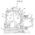
- the hydrokinetic coupler with fixed filling comprises, overall, an annular casing 10, which, formed, mainly, of two shells 10A, 10B, one forming a body, the other forming a cover, duly facing one another along a transverse joint plane 11, and duly secured to each other, for example by tie rods not visible in the figures, is crossed , axially, by a hollow shaft 12, with the interposition of rolling means 13.
- This shaft 12 is intended to be locked in rotation on the input shaft of the load to be driven, not shown.
- the casing 10 Jointly, by its shell 10A forming a body, the casing 10 is intended to be locked in rotation on the output shaft of any drive motor, also not shown.
- a generally toric working circuit 15 intended to contain a fluid not shown, namely a motor element 16A, which, integral with the housing 10, forms a pump , and a receiving element 16B, which forms a turbine and of which the shaft 12 is integral.
- 17A be the blades of the driving element 16A, and 17B those of the receiving element 16B.
- the motor element 16A is integral with the shell 10A forming the body of the casing 10, its blades 17A being directly carried by the latter, coming integrally therefrom.
- the shell 18 of the receiving element 16B is usually perforated with at least one bore 19, for balancing the pressures on one and the other of its faces.
- This bore 19, which intervenes between two blades 17B, may for example be circular.
- the mean diameter DM in question being defined as being at mid-distance between the inner peripheral diameter D1 and the outer peripheral diameter D2.
- holes 19 can thus be provided on the shell 18 of the receiving element 16B, for example being more or less regularly distributed circularly.
- the hydrokinetic coupler with fixed filling further comprises, connected to the working circuit 15, in order to reduce the quantity of fluid which is actually present there at start-up, two delay chambers which extend one and the other. other annularly around the axis X of the assembly, coaxially with respect to each other, namely, on the one hand, a first chamber 20, or main chamber, which is closest to the axis X, and a second chamber 22, or auxiliary chamber, which is the furthest therefrom.
- the main delay chamber 20 is connected to the working circuit 15, on the one hand, by a sampling channel, located towards the X axis, and, on the other hand, by a restitution channel, located more outside, and involving the intervention of calibrated nozzles.
- the auxiliary delay chamber 22 is also connected to the working circuit 15 by a sampling channel 25.
- this sampling channel 25 involves one or more holes 19 of the receiving element 16B, the auxiliary delay chamber 22 itself extends between the mean diameter DM of the receiving element 16B and its diameter external device D2, on the side of the receiving element, and the main delay chamber 20 extends inside the mean diameter DM of the receiving element 16B, also on the side of this receiving element 16B.
- the auxiliary retardation chamber 22 extends outside the shell 10B forming the cover of the casing 10, and preferably opposite the hole (s) 19 of the receiver element 16B, that is to say preferably according to a diameter corresponding substantially to the diameter along which this or these holes 19 extend, this shell 10B forming a cover itself presents, for participation in the constitution of the sampling channel 25, at least one bore 26.
- the auxiliary delay chamber 22 and the main delay chamber 20 are formed between the shell 10B forming the housing cover 10 and a cover 23 externally attached thereto, for example by screws. 24.
- the hole (s) 26 of the shell 10B forming the cover therefore open directly into the auxiliary delay chamber 22.
- the auxiliary delay chamber 22 can advantageously extend, if desired, and as shown, entirely in an overall volume whose diameter is at most of the order of outer peripheral diameter of the working circuit 15, assumed to be defined, as indicated above, by the diameter external device D2 of the receiving element 16B.
- the auxiliary delay chamber 22 can extend radially slightly beyond this outer peripheral diameter D2, the essential being that it remains radially below the outer peripheral diameter D3 of the casing 10.
- auxiliary retardation chamber 22 is moreover entirely circumscribed by the main retardation chamber 20.
- its volume represents a fraction, for example between 25% and 50% , of the volume of the working circuit 15.
- the fluid used is oil.
- part of the fluid is then derived from the working circuit 15 towards the auxiliary delay chamber 22 by the sampling channel 25.
- the auxiliary delay chamber 22 fills with fluid, by withdrawing it from the working circuit 15.
- the corresponding fluid withdrawal essentially results from the movement of the vortex, and not centrifugal force.
- the working circuit 15 thus being largely lightened with fluid, the drive motor can advantageously start without excessive load, at a substantially constant torque much lower than the nominal resistive torque in steady state.
- the characteristic curve I of the drive motor is shown in thin line, representative of the drive torque developed by this, and, in solid lines, the curve II representative of the drive torque CD, which, transmitted to the receiver element 16B, is available on the output shaft 12.
- the receiving element 16B When, at a time t2, the value thereof reaches that of the nominal resistive torque CN applied to the output shaft 12, the receiving element 16B, hitherto stationary, begins to be driven in rotation, which ensures the starting of the output shaft 12, and, by this, that of the load to be driven.
- the driven load then reaches its normal speed of rotation.
- the time t2 is of the order of 10 seconds, and the time t3 of the order of 30 to 40 seconds.
- the auxiliary delay chamber 22 extends inside the shell 10B forming the cover of the casing 10, between the latter and the receiving element 16B.
- the sampling channel 25 is therefore reduced to (x) only (s) drilling (s) 19 of this receiving element 16B.
- the auxiliary delay chamber 22 results at least in part from the fact that, between the shell 10A forming the body and the shell 10B forming the cover of the casing 10, a shim 30 is interposed axially, along their joint plane 11.
- the hydrokinetic coupler with fixed filling according to the invention advantageously has no moving part.
Landscapes
- Engineering & Computer Science (AREA)
- General Engineering & Computer Science (AREA)
- Mechanical Engineering (AREA)
- Arrangement And Driving Of Transmission Devices (AREA)
- Rotary Pumps (AREA)
- Hydraulic Clutches, Magnetic Clutches, Fluid Clutches, And Fluid Joints (AREA)
- Hydraulic Motors (AREA)
- Structures Of Non-Positive Displacement Pumps (AREA)
Claims (6)
- Hydrokinetische Kupplung mit fester Füllung, umfassend, einander gegenüber in einem Gehäuse (10) angeordnet, zwei Elemente, die miteinander einen ein Fluid enthaltenden Arbeitskreis (15) abgrenzen, und zwar ein Antriebselement (16A), das eine Pumpe bildet, und ein Empfangselement (16B), das eine Turbine bildet, mit zwei Verzögerungskammern, die mit dem Arbeitskreis (15) verbunden sind, um in diesem die Fluidmenge zu verringern, die in ihm beim Anfahren tatsächlich vorhanden ist, und die sich ringförmig um die Achse (X) der Einheit erstrecken, und zwar eine erste Kammer (20) oder Hauptkammer und eine zweite Kammer (22) oder Hilfskammer, dadurch gekennzeichnet, daß, wenn das Empfangselement (16B) mit mindestens einer Bohrung (19) versehen ist, der Entnahmeweg (25), der den Arbeitskreis (15) mit der Hilfsverzögerungskammer (22) verbindet, diese Bohrung (19) benutzt, diese auf der Hälfte des Empfangselements (16B) auftritt, die zwischen seinem mittleren Durchmesser (DM) und seinem Außenumfangsdurchmesser (D2) angeordnet ist, die Hilfsverzögerungskammer (22) sich ihrerseits zwischen diesen beiden Durchmessern (DM, D2) auf der Seite des Empfangselements (16B) erstreckt und die Hauptverzögerungskammer (20) sich innerhalb des mittleren Durchmessers (DM) des Empfangselements (16B) ebenfalls auf der Seite dieses Empfangselements (16B) erstreckt.
- Hydrokinetische Kupplung mit fester Füllung nach Anspruch 1, dadurch gekennzeichnet, daß das Volumen der Hilfsverzögerungskammer (22) einen Teil von beispielsweise 25% bis 50% des Volumens des Arbeitskreises (15) darstellt.
- Hydrokinetische Kupplung mit fester Füllung nach einem der Ansprüche 1, 2, dadurch gekennzeichnet, daß, wenn das Gehäuse (10) zwei Schalen (10A, 10B) umfaßt, deren eine einen Körper bildet, mit dem das Antriebselement (16A) fest verbunden ist, und deren andere einen Deckel bildet, die Hilfsverzögerungskammer (20) sich außerhalb der den Deckel bildenden Schale (10B) erstreckt und diese vorzugsweise gegenüber der Bohrung (19) des Empfangselements (16B) ihrerseits mindestens eine Bohrung (26) aufweist.
- Hydrokinetische Kupplung mit fester Füllung nach Anspruch 3, dadurch gekennzeichnet, daß die Hauptverzögerungskammer (20) und die Hilfsverzögerungskammer (22) zwischen der den Deckel bildenden Schale (10B) und einer an dieser angebrachten Kappe (23) gebildet sind.
- Hydrokinetische Kupplung mit fester Füllung nach einem der Ansprüche 1, 2, dadurch gekennzeichnet, daß, wenn das Gehäuse (10) zwei Schalen (10A, 10B) umfaßt, deren eine einen Körper bildet, mit dem das Antriebselement (16A) fest verbunden ist, und deren andere einen Deckel bildet, die Hilfsverzögerungskammer (22) sich im Inneren der den Deckel bildenden Schale (10B) zwischen dieser und dem Empfangselement (16B) erstreckt.
- Hydrokinetische Kupplung mit fester Füllung nach Anspruch 5, dadurch gekennzeichnet, daß die Hilfsverzögerungskammer (22) sich mindestens zum Teil daraus ergibt, daß zwischen der den Körper bildenden Schale (10A) und der den Deckel bildenden Schale (10B) axial eine Zwischenlage (30) dazwischengesetzt ist.
Applications Claiming Priority (2)
| Application Number | Priority Date | Filing Date | Title |
|---|---|---|---|
| FR9103031 | 1991-03-13 | ||
| FR9103031A FR2673987B1 (fr) | 1991-03-13 | 1991-03-13 | Coupleur hydrocinetique a remplissage fixe et chambres de retardement principale et auxiliaire. |
Publications (2)
| Publication Number | Publication Date |
|---|---|
| EP0504051A1 EP0504051A1 (de) | 1992-09-16 |
| EP0504051B1 true EP0504051B1 (de) | 1995-06-14 |
Family
ID=9410686
Family Applications (1)
| Application Number | Title | Priority Date | Filing Date |
|---|---|---|---|
| EP92400645A Expired - Lifetime EP0504051B1 (de) | 1991-03-13 | 1992-03-12 | Föttinger Kupplung mit fester Flüssigkeitsmenge und Haupt- und Hilfsverzögerungskammer |
Country Status (4)
| Country | Link |
|---|---|
| US (1) | US5251441A (de) |
| EP (1) | EP0504051B1 (de) |
| DE (1) | DE69202892T2 (de) |
| FR (1) | FR2673987B1 (de) |
Families Citing this family (12)
| Publication number | Priority date | Publication date | Assignee | Title |
|---|---|---|---|---|
| DE19614591A1 (de) * | 1996-04-12 | 1996-09-26 | Voith Turbo Kg | Hydrodynamische Kupplung |
| US5954746A (en) | 1997-10-09 | 1999-09-21 | Ethicon Endo-Surgery, Inc. | Dual cam trigger for a surgical instrument |
| DE59808700D1 (de) * | 1998-07-14 | 2003-07-17 | Alstom Switzerland Ltd | Berührungsloses Abdichten von Spalten in Gasturbinen |
| DE19859428A1 (de) * | 1998-12-22 | 2000-07-06 | Voith Turbo Kg | Hydrodynamische Kupplung |
| DE10115561A1 (de) * | 2001-03-28 | 2002-10-24 | Voith Turbo Kg | Hydrodynamische Kupplung |
| US6769248B2 (en) * | 2002-06-13 | 2004-08-03 | Turbo Research, Inc. | Fluid coupling for mobile equipment |
| DE10361440B4 (de) * | 2003-12-23 | 2015-08-06 | Voith Turbo Gmbh & Co. Kg | Hydrodynamische Strömungsmaschine mit Verschluss mit thermischer Sicherungsfunktion |
| DE102004059833A1 (de) * | 2004-12-10 | 2006-06-14 | Voith Turbo Gmbh & Co. Kg | Verfahren zum Regeln der maximalen Drehzahl einer Arbeitsmaschine und hydrodynamische Kupplung hierfür |
| DE102006017975B3 (de) * | 2006-04-13 | 2007-08-23 | Voith Turbo Gmbh & Co. Kg | Hydrodynamische Kupplung |
| DE102008031905A1 (de) * | 2008-07-08 | 2010-01-14 | Voith Patent Gmbh | Verschluss mit thermischer Sicherungsfunktion für eine hydrodynamische Maschine |
| DE102010004835A1 (de) * | 2010-01-15 | 2011-07-21 | Voith Patent GmbH, 89522 | Hydrodynamische Maschine und Verfahren zur Minimierung der Schleppleistung einer solchen |
| US12104662B1 (en) * | 2023-09-12 | 2024-10-01 | Cheng-Jiang Hou | Coupling |
Citations (1)
| Publication number | Priority date | Publication date | Assignee | Title |
|---|---|---|---|---|
| US3165894A (en) * | 1962-08-13 | 1965-01-19 | American Radiator & Standard | Torque limiting ports-fluid drives |
Family Cites Families (11)
| Publication number | Priority date | Publication date | Assignee | Title |
|---|---|---|---|---|
| US2133029A (en) * | 1936-02-20 | 1938-10-11 | American Voith Contact Co | Turbo coupling |
| US2245684A (en) * | 1938-07-28 | 1941-06-17 | Deschimag | Hydraulic coupling |
| US2423812A (en) * | 1939-04-29 | 1947-07-08 | American Voith Contact Co | Thermostatic outlet valve control for fluid coupling |
| FR1225225A (fr) * | 1958-05-09 | 1960-06-29 | American Radiator & Standard | Accouplement hydraulique |
| US2987887A (en) * | 1958-08-14 | 1961-06-13 | Gen Motors Corp | Hydraulic coupling with fluid content control |
| FR1416023A (fr) * | 1964-11-10 | 1965-10-29 | Voith Turbo K G | Accouplement hydraulique, notamment pour transmission à moteur électrique |
| CH600191A5 (de) * | 1975-01-17 | 1978-06-15 | Voith Turbo Kg | |
| JPS57129931A (en) * | 1981-02-02 | 1982-08-12 | Hitachi Ltd | Controller for rotational frequency of rotary machine |
| DE3318462C2 (de) * | 1983-05-20 | 1986-10-09 | Bergwerksverband Gmbh, 4300 Essen | Hydrodynamische Kupplung |
| DE3522174C1 (de) * | 1985-06-21 | 1986-05-22 | Voith-Turbo Gmbh & Co Kg, 7180 Crailsheim | Hydrodynamische Kupplung |
| FR2618865B1 (fr) * | 1987-07-29 | 1991-07-05 | Valeo | Dispositif amortisseur de couple |
-
1991
- 1991-03-13 FR FR9103031A patent/FR2673987B1/fr not_active Expired - Lifetime
-
1992
- 1992-02-18 US US07/836,542 patent/US5251441A/en not_active Expired - Lifetime
- 1992-03-12 DE DE69202892T patent/DE69202892T2/de not_active Expired - Lifetime
- 1992-03-12 EP EP92400645A patent/EP0504051B1/de not_active Expired - Lifetime
Patent Citations (1)
| Publication number | Priority date | Publication date | Assignee | Title |
|---|---|---|---|---|
| US3165894A (en) * | 1962-08-13 | 1965-01-19 | American Radiator & Standard | Torque limiting ports-fluid drives |
Also Published As
| Publication number | Publication date |
|---|---|
| DE69202892T2 (de) | 1995-11-23 |
| FR2673987B1 (fr) | 1995-09-22 |
| FR2673987A1 (fr) | 1992-09-18 |
| EP0504051A1 (de) | 1992-09-16 |
| US5251441A (en) | 1993-10-12 |
| DE69202892D1 (de) | 1995-07-20 |
Similar Documents
| Publication | Publication Date | Title |
|---|---|---|
| EP0504051B1 (de) | Föttinger Kupplung mit fester Flüssigkeitsmenge und Haupt- und Hilfsverzögerungskammer | |
| FR2768271A1 (fr) | Procede de fabrication d'un rotor pour machine electrique rotative, rotor et machine concernes | |
| FR2487004A1 (fr) | Systeme d'entrainement de la soufflante de turbomachines | |
| FR2716311A1 (fr) | Dispositif de déconnexion d'entraînement pour un générateur électrique refroidi par huile. | |
| FR2732725A1 (fr) | Pompe de carburant et procede pour sa fabrication | |
| FR2817289A1 (fr) | Dispositif de centrage d'un tube dans un arbre de turbine | |
| EP0036216B1 (de) | Hydrodynamischer Drehmomentwandler mit Überbrückungsvorrichtung | |
| EP1653053A2 (de) | Zwei-Steifigkeiten Vorrichtung für die Montage eines Lagers auf die Welle eines Rotationsmotor | |
| FR2816686A1 (fr) | Dispositif d'amortissement de vibration en torsion pour embrayage de vehicule automobile | |
| FR2726949A1 (fr) | Generateur de charge pour vehicule | |
| WO1999001682A1 (fr) | Appareil d'accouplement hydrocinetique a embrayage de verrouillage, pour vehicule automobile | |
| FR2499326A1 (fr) | Rotor d'une machine electrique a grande vitesse | |
| FR2653843A1 (fr) | Coupleur hydrocinetique a limitation de couple amelioree au demarrage et surcouple reglable au ralentissement. | |
| WO2003072936A1 (fr) | Demarreur electrique a butee d'amortissement pour le lanceur | |
| FR2676521A1 (fr) | Coupleur hydrocinetique a remplissage fixe et chambre de retardement interne au circuit de travail. | |
| FR2517775A1 (fr) | Dispositif d'embrayage hydraulique commande par la temperature | |
| FR2742828A1 (fr) | Accouplement visqueux de ventilateur, a chambre de reserve a remplissage fonction de la force centrifuge | |
| EP0015167B1 (de) | Verbesserung an Wechselstrommaschinen von Kraftfahrzeugen | |
| FR2621963A1 (fr) | Accouplement elastique rotatif | |
| EP1609234B1 (de) | Elektromagnetische fahrzeugbremse | |
| FR2547384A1 (fr) | Convertisseur de couple equipe d'un dispositif de commande d'enclenchement | |
| FR2725146A1 (fr) | Procede pour realiser une liaison sertie entre un insert et une piece tubulaire | |
| FR2503308A1 (fr) | Transmission a organe d'accouplement hydraulique et embrayage de verrouillage | |
| FR2809150A1 (fr) | Amortisseur d'oscilations de torsion | |
| BE551231A (de) |
Legal Events
| Date | Code | Title | Description |
|---|---|---|---|
| PUAI | Public reference made under article 153(3) epc to a published international application that has entered the european phase |
Free format text: ORIGINAL CODE: 0009012 |
|
| AK | Designated contracting states |
Kind code of ref document: A1 Designated state(s): BE DE FR GB IT |
|
| 17P | Request for examination filed |
Effective date: 19921009 |
|
| 17Q | First examination report despatched |
Effective date: 19931018 |
|
| GRAA | (expected) grant |
Free format text: ORIGINAL CODE: 0009210 |
|
| AK | Designated contracting states |
Kind code of ref document: B1 Designated state(s): BE DE FR GB IT |
|
| GBT | Gb: translation of ep patent filed (gb section 77(6)(a)/1977) |
Effective date: 19950612 |
|
| REF | Corresponds to: |
Ref document number: 69202892 Country of ref document: DE Date of ref document: 19950720 |
|
| ITF | It: translation for a ep patent filed | ||
| PLBE | No opposition filed within time limit |
Free format text: ORIGINAL CODE: 0009261 |
|
| STAA | Information on the status of an ep patent application or granted ep patent |
Free format text: STATUS: NO OPPOSITION FILED WITHIN TIME LIMIT |
|
| 26N | No opposition filed | ||
| REG | Reference to a national code |
Ref country code: GB Ref legal event code: IF02 |
|
| PGFP | Annual fee paid to national office [announced via postgrant information from national office to epo] |
Ref country code: IT Payment date: 20110322 Year of fee payment: 20 Ref country code: FR Payment date: 20110401 Year of fee payment: 20 |
|
| PGFP | Annual fee paid to national office [announced via postgrant information from national office to epo] |
Ref country code: DE Payment date: 20110411 Year of fee payment: 20 Ref country code: BE Payment date: 20110328 Year of fee payment: 20 Ref country code: GB Payment date: 20110324 Year of fee payment: 20 |
|
| REG | Reference to a national code |
Ref country code: DE Ref legal event code: R071 Ref document number: 69202892 Country of ref document: DE |
|
| REG | Reference to a national code |
Ref country code: DE Ref legal event code: R071 Ref document number: 69202892 Country of ref document: DE |
|
| BE20 | Be: patent expired |
Owner name: *SIME INDUSTRIE Effective date: 20120312 |
|
| REG | Reference to a national code |
Ref country code: GB Ref legal event code: PE20 Expiry date: 20120311 |
|
| PG25 | Lapsed in a contracting state [announced via postgrant information from national office to epo] |
Ref country code: DE Free format text: LAPSE BECAUSE OF EXPIRATION OF PROTECTION Effective date: 20120313 |
|
| PG25 | Lapsed in a contracting state [announced via postgrant information from national office to epo] |
Ref country code: GB Free format text: LAPSE BECAUSE OF EXPIRATION OF PROTECTION Effective date: 20120311 |