EP0504039B1 - Verfahren und Vorrichtung zur Herstellung eines ringförmigen Werkstückes aus Blech - Google Patents
Verfahren und Vorrichtung zur Herstellung eines ringförmigen Werkstückes aus Blech Download PDFInfo
- Publication number
- EP0504039B1 EP0504039B1 EP92400625A EP92400625A EP0504039B1 EP 0504039 B1 EP0504039 B1 EP 0504039B1 EP 92400625 A EP92400625 A EP 92400625A EP 92400625 A EP92400625 A EP 92400625A EP 0504039 B1 EP0504039 B1 EP 0504039B1
- Authority
- EP
- European Patent Office
- Prior art keywords
- metal sheet
- sheet
- fastening
- axis
- turntable
- Prior art date
- Legal status (The legal status is an assumption and is not a legal conclusion. Google has not performed a legal analysis and makes no representation as to the accuracy of the status listed.)
- Expired - Lifetime
Links
- 238000000034 method Methods 0.000 title claims description 16
- 229910052751 metal Inorganic materials 0.000 claims description 38
- 239000002184 metal Substances 0.000 claims description 38
- 238000005452 bending Methods 0.000 claims description 27
- 238000003466 welding Methods 0.000 claims description 25
- 238000003754 machining Methods 0.000 claims description 14
- 238000004519 manufacturing process Methods 0.000 claims description 8
- 238000010438 heat treatment Methods 0.000 claims description 6
- 238000004804 winding Methods 0.000 claims description 5
- 238000003825 pressing Methods 0.000 claims description 3
- 229910001069 Ti alloy Inorganic materials 0.000 claims description 2
- 238000005096 rolling process Methods 0.000 claims description 2
- 238000004513 sizing Methods 0.000 claims 2
- XKRFYHLGVUSROY-UHFFFAOYSA-N Argon Chemical compound [Ar] XKRFYHLGVUSROY-UHFFFAOYSA-N 0.000 description 4
- RTAQQCXQSZGOHL-UHFFFAOYSA-N Titanium Chemical compound [Ti] RTAQQCXQSZGOHL-UHFFFAOYSA-N 0.000 description 3
- 239000010936 titanium Substances 0.000 description 3
- 229910052719 titanium Inorganic materials 0.000 description 3
- 229910052786 argon Inorganic materials 0.000 description 2
- 238000001816 cooling Methods 0.000 description 2
- 239000007789 gas Substances 0.000 description 2
- 239000000126 substance Substances 0.000 description 2
- 229910045601 alloy Inorganic materials 0.000 description 1
- 239000000956 alloy Substances 0.000 description 1
- 238000004873 anchoring Methods 0.000 description 1
- 230000005587 bubbling Effects 0.000 description 1
- 230000000295 complement effect Effects 0.000 description 1
- 238000007796 conventional method Methods 0.000 description 1
- 238000010586 diagram Methods 0.000 description 1
- 238000009499 grossing Methods 0.000 description 1
- 230000012447 hatching Effects 0.000 description 1
- 230000001788 irregular Effects 0.000 description 1
- 238000012423 maintenance Methods 0.000 description 1
- 150000002739 metals Chemical class 0.000 description 1
- 230000001681 protective effect Effects 0.000 description 1
- 238000007493 shaping process Methods 0.000 description 1
- 229910000679 solder Inorganic materials 0.000 description 1
- 238000003892 spreading Methods 0.000 description 1
Images


Classifications
-
- B—PERFORMING OPERATIONS; TRANSPORTING
- B21—MECHANICAL METAL-WORKING WITHOUT ESSENTIALLY REMOVING MATERIAL; PUNCHING METAL
- B21D—WORKING OR PROCESSING OF SHEET METAL OR METAL TUBES, RODS OR PROFILES WITHOUT ESSENTIALLY REMOVING MATERIAL; PUNCHING METAL
- B21D5/00—Bending sheet metal along straight lines, e.g. to form simple curves
- B21D5/14—Bending sheet metal along straight lines, e.g. to form simple curves by passing between rollers
- B21D5/143—Bending sheet metal along straight lines, e.g. to form simple curves by passing between rollers making use of a mandrel
-
- B—PERFORMING OPERATIONS; TRANSPORTING
- B21—MECHANICAL METAL-WORKING WITHOUT ESSENTIALLY REMOVING MATERIAL; PUNCHING METAL
- B21D—WORKING OR PROCESSING OF SHEET METAL OR METAL TUBES, RODS OR PROFILES WITHOUT ESSENTIALLY REMOVING MATERIAL; PUNCHING METAL
- B21D51/00—Making hollow objects
- B21D51/02—Making hollow objects characterised by the structure of the objects
- B21D51/10—Making hollow objects characterised by the structure of the objects conically or cylindrically shaped objects
Definitions
- the invention relates to the manufacture of annular parts by means of a generally flat sheet and whose initial shape is predetermined to constitute, once deformed, the annular part to be obtained.
- the invention advantageously applies when machining is to be carried out on this part.
- the invention has been developed more particularly for developing a slightly conical front ferrule of an airplane turbojet engine casing.
- Dual-flow turbojets are one type of propulsion engine for airplanes. Their overall shape is similar to a cylinder several meters long, the outside diameter constantly varying according to the constitution of the different parts of the engine. For example, at the level of the cold flow channel surrounding the turbojet engine, the casing assumes a shape which widens slightly to then become cylindrical and finally resume a conical shape to reduce the diameter of this cold flow channel.
- the motor casing therefore often consists of a succession of annular ferrules, the shapes of which are more or less complicated and on which numerous machining operations are planned, intended for the fixing of various accessories (control means, pipeline, control means , ). In addition, machining intended to hollow out the shell to lighten it is often carried out.
- a ferrule before a casing at the level of the cold flow channel can consist of a titanium ferrule, slightly conical and whose diameter can be between 500 and 1000 mm. She is often obtained from a sheet whose thickness is around 7 mm and which is then hollowed out by machining to lighten this part and provide for the fixing of various accessories while leaving ribs to stiffen the part. Such a part can be obtained in different ways.
- a conventional method for forming the sheet more commonly known as "wrapping" consists of bending or bending the sheet between several rollers placed on either side of it. The final radius of curvature is obtained by successive passage of the sheet between these rollers. Once bent, the shell is then finished by welding along two generators, using conventional equipment.
- This method requires the machining to be carried out after this bending or bending operation, since the pressure forces of the rollers would lead to the crushing or the inclination of the numerous ribs resulting from the machining. It is then necessary to machine the part after this bending, which proves to be relatively difficult and costly. Indeed, machining a ferrule whose diameter is around 800 mm and comprising in many places a thickness of 1 or 2 mm is very delicate. Such machining can however be obtained chemically, the shell being immersed in a large tank provided for this purpose. At this level, this method is very expensive and difficult to implement.
- Another technique used consists in bending by successive folds using a conventional folding machine.
- the folds are made according to the generatrices which have a reduced inertia compared to the others.
- This technique has the disadvantage that fold marks on the ribs remain after this bending operation.
- the metal is subjected to stresses exceeding the elastic limit or the modulus of elasticity of this metal.
- FR-A-1 223 970 describes a device for manufacturing envelopes enabling a sheet to be bent by means of a pressure roller around a winding drum.
- the drum has a clamping bar and is associated with a welding and smoothing device for welding the two ends of the sheet.
- the object of the invention is to produce such a type of parts while endeavoring to carry out the shaping of the sheet in the form of a ferrule after having carried out all the necessary machining operations on the flat sheet, in order to avoid recourse to chemical machining.
- a first main object of the invention is a method of manufacturing an annular piece of axis of revolution, from a flat sheet of titanium alloy whose shape is predimensioned for this purpose.
- the fixing flange and the fixing block are joined to the flange and to the movable block, leaving a light on each side of the sheet at the junction of the two ends to be welded, in order to allow welding before the tool is removed from the formed part.
- the tool comprises hooks fixed on the movable flange and intended to be hung around the fixing flange and fixing blocks, adjusting screws being screwed into the hooks to allow the complete bringing together of the two ends opposite to solder.
- the welding head can advantageously be mounted on the turntable, movable in translation along the junction to be welded.
- FIGs 1A to 1F illustrate the bending according to the invention of a sheet 2 followed by a welding phase of this sheet 2.
- first fixing means consist of a fixing block 10 and a fixing flange 36.
- the sheet 2 is thus fixed tangentially to this turntable 6.
- a roller 4 mounted rotating around a second axis 5 is placed next to the turntable 6, so that its periphery is very close to the fixing block 10 of the turntable 6 when the latter is rotated.
- This roller 4 is a pressure roller.
- the fixing block 10 of the turntable 6 drives the sheet 2 around the turntable 6.
- the presence of the pressure roller 4 keeps the sheet near the turntable 6 by pressing on its external surface 2E. It follows a start of winding of the sheet 2 by twisting or bending around the turntable 6.
- several internal supports 8 are fixed to the periphery of the turntable 6 in the same way as the fixing block 10. The top 9 of each internal support 8 is placed at a distance from the vertical axis of rotation 7 of the turntable 6 equal to the radius of the part to be obtained.
- the sheet metal 2 is wound around the turntable 6, the pressure roller 4 applying the interior surface 2I of the sheet 2 against the tops 9 of the interior supports 8.
- the support brackets 14 each placed opposite an internal support 8. The sheet 2 is thus forced to remain in place around of the turntable 6 and the internal supports 8, whatever the stresses generated by this deformation.
- FIG. 1D represents the end of the bending of the sheet 2 when the last internal support 8Z arrives opposite the pressure roller 4.
- the second end 1 of sheet 2, or rear end is always free.
- mobile fixing means have been previously fixed to this second end 1 of the sheet 2. They consist of a mobile block 11 and a mobile flange 12. This mobile flange 12 is provided with at least two hooks 13 intended to be hooked around the flange 36 and the fixing block 10 of the turntable 6.
- the second main phase of the process according to the invention consists in welding the two ends 1 and 3 thus joined together.
- Figure 1F symbolizes this welding operation by the arrow perpendicular to the sheet 2 indicating the junction point of the two ends 1 and 3 of the sheet 2.
- the shapes of the fastening elements are such that the welding operation can be carried out before dismantling the sheet 2 thus bent on the tools.
- the annular part thus formed 20 has therefore been bent and welded.
- the initial sheet 2 has of course been prepared and dimensioned so that, after bending, the two ends 1 and 3 are opposite one another and allow welding.
- the formed part 20 is subjected to an expansion heat treatment. This may consist in subjecting the part 20 to a temperature in the region of 500 ° C (450 to 550 ° C) for a period of approximately four hours (between two and six hours), in particular in the case of alloy parts titanium.
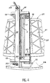
- FIG. 2 shows a tool making it possible to implement the process which has just been described, and more particularly for obtaining a ferrule before a casing of a turbofan engine with double flow, at the level of the cold flow channel.
- a ferrule is provided in titanium which is a resistant metal, having good machinability, and a relatively light density compared to other metals.
- This ferrule is made from a sheet whose thickness is approximately 7 mm. However, it is necessary to hollow out this sheet to make it even lighter.
- These recesses 21 are provided so that ribs 22 remain on the surface of the part, so that the latter retains sufficient rigidity.
- Many forms are provided in such a ferrule 20. For example, two bosses 23 have been shown on this ferrule 20. The ferrule 20 is therefore a part frequently and irregularly having extra thicknesses.
- the initial sheet 2 is shown with a slightly twisted elongated rectangle shape. Such a shape therefore corresponds to the developed shape of the final ferrule 20.
- the sheet is in the process of bending.
- stirrups 14 which have already been placed opposite their corresponding internal supports 8. They are mounted by their respective feet 15, preferably on a base 24 of the tool. The latter is mounted on the turntable 6 of a machine 29. Radial grooves 17 allow the positioning of the tool on this turntable 6.
- the fixing block is covered with a fixing flange 36 through which pass at least two groups of fixing screws 37 which fix this first end 3 of the sheet relative to the fixing block. Holes are provided for this in the sheet.
- the second end 1 of the sheet has been shown in its initial form, that is to say flat.
- the internal face 2I is therefore still visible and is intended to be applied against the last internal support 8Z, the support half-cylinder of which is still visible.
- FIG. 3 shows in detail the fixing stirrups 14 of the sheet on the interior supports 8.
- These stirrups 14 consist of a metal bar terminated by a hook 28 which is housed behind the upper part of the interior support 8, in a notch 27.
- the pressure applied to the external surface of the sheet is obtained by screwing several screws 18 screwed into the main part of the stirrup 14 and whose enlarged end acts by pressure on the sheet.
- the fixing of these stirrups 14 on the internal supports 8 is also made in the lower part thanks to a notch 25 formed in the lower part of the stirrup 14 and a fixing bolt 26 mounted in the foot 15 of each of the internal supports 8.
- the internal supports are mounted by their feet 15 by means of screws 51 on the base 24. Oblong holes 50 in the feet 15 make it possible to adapt this tool to several different diameters of ferrules to be obtained. Thus, by spreading the interior supports more or less 8 it is easy to increase or decrease the diameter of the part to be obtained.
- the adjustment of the position of the internal supports 8 can be obtained by means of a stop 30 into which is screwed an adjustment screw 31 acting at the base of the foot 15 of each internal support 8.
- the operational part of the internal supports 8 has been shown in the form of a half-cylinder 9, the generator of which being at the top of the latter is the part on which the sheet is supported.
- This type of interior support is only an embodiment, other equivalent elements that can be imagined and used to produce a series of sufficient supports inside the sheet.
- FIG. 4 corresponds to the phase of the process represented by FIG. 1E.
- the sheet is completely bent and forms a ferrule 20, the two ends 1 and 3 glued being one against the other.
- This Figure 4 shows in detail the means for fixing the two ends 1 and 3 of the sheet, so that they are joined against one another.
- the fixing block is covered with the fixing flange 36 covering the first end 3.
- the second end 1 of the sheet is covered by the movable flange 12 which passes through two other groups of fixing screws 35 which fix this second end in the block of fixation.
- hooks 13 shown in FIGS. 1D, 1E are fixed on the movable flange 12. Their shape allows them to hang behind the block and the fixing flange 36. Once put in place, they are locked in this position by a fixing bar 32 held tight against the fixing flange by means of two bolts 33.
- the fixing flange 36 and the movable flange 12, once the two ends 1 and 3 of the sheet are joined against one another form a groove 34 at the bottom of which is the junction plane of these two ends 1 and 3.
- This groove makes it possible to weld the two ends 1 and 3 of the sheet before the tool for clamping and holding the sheet is removed.
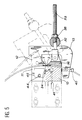
- FIG. 5 The operation of the fixing mechanism of these two ends 1 and 3 is explained by FIG. 5.
- the fixing block 10 Fixed on the base.
- the first end 3 of the sheet which is held against it by the fixing flange 36.
- the movable block 11 and the movable flange 12 are the movable flange 12 in which the second is fixed. end 1 of the sheet.
- the assembly or movable block 11 has a shape complementary to that of the fixing block 10 in order to be able to be housed in the latter.
- the bolt 33 is introduced into a hole made through the hook 13.
- the complete screwing allows the hook 13 to be placed behind the block 10 and the fixing flange 36 and thereby place the second end 1 of the sheet against the first 3.
- the tool according to the invention provides for the use of a tension screw 40 screwed into the hook 13 and being able to protrude inside of it to come to bear against the fixing block 10. A screwing of this tensioning screw 40 makes it possible to tension the sheet by bringing the second end 1 closer to the sheet from the first 3.
- a pipe 41 which opens into the interior of the slot 34 formed by the fixing block 10 and the movable block 11 below the two ends 1 and 3 of the sheet.
- This pipe 41 symbolizes a gas inlet network, preferably argon, to ensure minimum gas circulation during the welding operation which is carried out when the clamping tool is still mounted on the sheet.
- This same tool for fixing the two ends 1 and 3 of the sheet is also detailed in another way in FIG. 6.
- This in fact represents the fixing block 10 into which the movable flange must be inserted.
- this fixing block 10 has a cavity 42 making it possible to delimit a part of the slot which must be placed under the junction point of the two ends 1 and 3 of the sheet. In this cavity 42 open several pipes 41 allowing the supply of argon during the welding.
- the movable flange 12 At the upper and lower ends of the movable flange 12 is placed another adjusting screw 44 for positioning the two ends 1 and 3 of the sheet. Indeed, the bending of the initial sheet 2 which may have relatively irregular shapes and thicknesses can lead to the fact that the two ends 1 and 3 of this sheet are not strictly opposite one another. It is then necessary to adjust the height of one of these ends relative to the other. By using the adjustment screws 44 screwed into two positioning tabs 45 of the movable block 11 and coming to bear against the fixing block 10, it is thus possible to make this adjustment.
- the two ends 1 and 3 of the sheet can thus be positioned with precision, as shown by the arrows, before the welding is carried out.
- the operation consisting in welding the two ends 1 and 3 of the sheet is preferably carried out when the bending and fixing tool on this tool is still fixed on the bent sheet. It is even provided that the welding head is mounted on the machine or the frame of the machine supporting the turntable 6. This assembly can be carried out so as to that the welding head is mounted movable in translation to perform welding along the entire height of the sheet to weld in a single operation the bent sheet.
- the turntable 6 can be mounted on a support itself mounted pivoting about a vertical axis 16 so as to rotate 90 ° the entire turntable and l 'tool so as to put the ferrule thus formed in a position where its axis of revolution is horizontal.
- the welding head can thus be used if it is mounted movable in horizontal translation on the frame 29 on which the tooling is mounted.
- a main advantage of the invention is that all the machining which it is necessary to perform on the shell in order to be able to manufacture complicated parts, such as a shell before a crankcase of a two-phase turbojet engine, can be done before this bending operation.
- the chemical machining used beforehand to shape the shapes after the shell has been formed requires bubbling in tanks.
- the shape of a ferrule requires the use of very large tanks, which makes the process difficult and expensive.
- Another advantage of the invention is that it simply requires the presence of a frame or a turntable machine.
Landscapes
- Engineering & Computer Science (AREA)
- Mechanical Engineering (AREA)
- Butt Welding And Welding Of Specific Article (AREA)
- Bending Of Plates, Rods, And Pipes (AREA)
Claims (6)
- Verfahren zur Herstellung eines ringförmigen Werkstücks (20) mit einer Drehachse (7) aus einem zu diesem Zweck vordimensionierten flachen Blech (2) aus einer Titanlegierung,
dadurch gekennzeichnet, daß nacheinander- auf wenigstens einer (2E) der beiden Flächen des Blechs (2) ein Netz von Rippen (22) sowie gemusterte Formen (23) flach herausgearbeitet werden,- das Blech (2) schrittweise um die Drehachse (7) rundgebogen wird, indem es von einem ersten Ende (3) her und mittels einer Druckwalze (4) aufgewickelt wird, die durch Rollen auf einer der Flächen des Blechs (2), die zu der Außenfläche (2E) des ringförmigen Werkstücks (20) wird, einen Druck ausübt, unter Verwendung von inneren Abstützungen (8), die dazu dienen, die Innenfläche (2I) des Blechs (2) während des Rundbiegevorgangs zu führen, und von Haltebügeln (14), die jeweils einer der inneren Abstützungen (8) gegenüberliegen, um das so verformte Blech (2) zu halten, so daß die beiden entgegengesetzten Enden (1, 3) miteinander vereinigt werden, wobei Verformungskräfte eingesetzt werden, die unterhalb der Elastizitätsgrenze des Metalls bleiben, aus dem das Blech (2) besteht,- die beiden zusammengefügten Enden (1, 3) des Blechs (2) verschweißt werden,- eine thermische Entspannungsbehandlung für die Bleche durch Erwärmen auf eine Temperatur zwischen 450 und 550°C während einer Dauer von 2 bis 6 Stunden durchgeführt wird und schließlich- eine thermische Kalibrierung durchgeführt wird. - Vorrichtung zur Herstellung eines ringförmigen Werkstücks (20) mit einer Drehachse (7) aus einem zu diesem Zweck vordimensionierten flachen Blech (2) durch- flaches Herausarbeiten eines Netzes von Rippen (22) sowie gemusterter Formen (23) auf wenigstens einer (2E) der beiden Flächen des Blechs (2),- schrittweises Rundbiegen des Blechs (2) um die Drehachse (7), indem das Blech (2) von einem ersten Ende (3) her aufgewickelt wird, und indem auf die Außenfläche (2E) des Blechs (2), die die Außenfläche (2E) des ringförmigen Werkstücks (20) wird, Druck ausgeübt wird, so daß die beiden Enden (1, 3) des Blechs miteinander vereinigt werden, wobei Verformungskräfte eingesetzt werden, die unterhalb der Elastizitätsgrenze des Metalls bleiben,- Verschweißen der beiden zusammengefügten Enden (1, 3) des Blechs (2)- thermische Entspannungsbehandlung zwischen 450 und 550°C während einer Dauer von 2 bis 6 Stunden und- thermische Kalibrierung,wobei die Vorrichtung aufweist,- Einspannmittel zum Einspannen des ersten Endes (3) des Blechs (2) in einer der Neigung der Mantellinien des ausgebildeten Werkstücks (20) entsprechenden Neigung gegenüber der Drehachse (7),- eine Druckwalze (4), die um eine zu der Neigung der Mantellinien parallele und zu der Drehachse (7) koplanare Rotationsachse (5) drehbar montiert ist,gekennzeichnet durch- einen um die mit der Drehachse des herzustellenden ringförmigen Werkstücks (20) zusammenfallende Rotationsachse (7) rotierenden, durch Antriebsmittel mit einer Drehbewegung beaufschlagten Drehteller (6), auf dem innere Abstützungen (8) verstellbar befestigt sind, die jeweils als Halbzylinder ausgebildet sind, wobei die von der Achse (7) des Drehtellers (6) am weitesten entfernte Mantellinie des Halbzylinders Abstützpunkte bildet, um die Innenfläche (2I) des Blechs (2) während des Rundbiegens zu führen, und wobei der Drehteller die Einspannmittel zum Einspannen des ersten Endes (3) des Blechs (2) umfaßt, an den das erste Ende (3) des Blechs (2) eingespannt wird,- Spannbügel (14), die jeweils einer inneren Abstützung (8) gegenüberliegen, zum Halten des Blechs (2) während des Rundbiegevorgangs- Einspannmittel zum Spannen des zweiten Endes (1) des Blechs (2) gegen das erste Ende (3) des Blechs (2).
- Vorrichtung nach Anspruch 2, dadurch gekennzeichnet, daß die Einspannmittel zum Einspannen der Enden aufweisen:- einen Spannblock (10), der auf dem Drehteller (6) fest montiert ist,- einen Spannflansch (36) zum Einspannen des ersten Endes (3) an dem Spannblock (10),- einenbewegbaren Block (11),- einen bewegbaren Flansch (12) zum Einspannen des zweiten Endes (1) des Blechs (2) an dem bewegbaren Block (11) in der Nähe des ersten Endes (3) des Blechs (2) und- Spannschrauben (35, 37) zum Spannen der bewegbaren Flansche (12) und der Befestigungsflansche (36).
- Vorrichtung nach Anspruch 3, dadurch gekennzeichnet, daß der bewegbare Flansch (12) und der bewegbare Block (11) im Bereich der Verbindungsstelle der beiden Enden (1, 3) des Blechs (2) mit dem Spannflansch (36) und dem Spannblock (10) aneinanderstoßen, wobei sie auf jeder Seite der Flächen des Blechs (2) einen Spalt (34) freilassen, um das Schweißen zu ermöglichen, bevor die Vorrichtung von dem hergestellten Werkstück gelöst wird.
- Vorrichtung nach Anspruch 4, gekennzeichnet durch an dem bewegbaren Flansch (12) befestigte Haken (13) zum Umklammern des Spannflansches (36) und der Spannblöcke (10), wobei in diese Haken (13) Einstellschrauben (40) eingeschraubt sind, die ein vollständiges Annähern der beiden miteinander zu verschweißenden entgegengesetzten Enden (1, 3) ermöglichen.
- Vorrichtung nach einem der Ansprüche 4 oder 5, gekennzeichnet durch einen auf dem Drehteller (6) montierten Schweißkopf, der in einer Translationsbewegung in Richtung der Verbindungsstelle der beiden zu verschweißenden Enden (1, 3) verschiebbar ist.
Applications Claiming Priority (2)
| Application Number | Priority Date | Filing Date | Title |
|---|---|---|---|
| FR9103066A FR2673863B1 (fr) | 1991-03-14 | 1991-03-14 | Procede et outillage de fabrication d'une piece annulaire en tole. |
| FR9103066 | 1991-03-14 |
Publications (2)
| Publication Number | Publication Date |
|---|---|
| EP0504039A1 EP0504039A1 (de) | 1992-09-16 |
| EP0504039B1 true EP0504039B1 (de) | 1995-12-27 |
Family
ID=9410707
Family Applications (1)
| Application Number | Title | Priority Date | Filing Date |
|---|---|---|---|
| EP92400625A Expired - Lifetime EP0504039B1 (de) | 1991-03-14 | 1992-03-11 | Verfahren und Vorrichtung zur Herstellung eines ringförmigen Werkstückes aus Blech |
Country Status (4)
| Country | Link |
|---|---|
| US (1) | US5341665A (de) |
| EP (1) | EP0504039B1 (de) |
| DE (1) | DE69207034T2 (de) |
| FR (1) | FR2673863B1 (de) |
Families Citing this family (6)
| Publication number | Priority date | Publication date | Assignee | Title |
|---|---|---|---|---|
| ATE249293T1 (de) * | 2000-12-04 | 2003-09-15 | Trumpf Werkzeugmaschinen Gmbh | Maschine für die bearbeitung von werkstücken, insbesondere von blechen, mit wenigstens einer biegestation sowie wenigstens einer fügevorrichtung |
| GB2425079B (en) | 2005-04-11 | 2007-08-22 | Rolls Royce Plc | Method of manufacturing a duct for a gas turbine engine |
| US8881396B2 (en) | 2011-02-07 | 2014-11-11 | Revcor, Inc. | Method of manufacturing a fan assembly |
| US9452464B2 (en) | 2011-07-06 | 2016-09-27 | Federal-Mogul Corporation | Method of forming a tubular member |
| CN107738054A (zh) * | 2017-09-30 | 2018-02-27 | 中国航发沈阳发动机研究所 | 焊接式机匣的焊接定位方法 |
| US11274677B2 (en) | 2018-10-25 | 2022-03-15 | Revcor, Inc. | Blower assembly |
Family Cites Families (12)
| Publication number | Priority date | Publication date | Assignee | Title |
|---|---|---|---|---|
| US2315535A (en) * | 1940-04-16 | 1943-04-06 | American Can Co | Blank feeder for can bodymakers |
| FR1223970A (fr) * | 1958-05-14 | 1960-06-21 | Bell Ag Maschf | Dispositif de courbage, calibrage, soudage et lissage d'éléments de tôle pour la fabrication d'enveloppes |
| SU411940A1 (de) * | 1969-09-08 | 1974-01-25 | ||
| FR2311607A1 (fr) * | 1975-05-20 | 1976-12-17 | Mediterranee Const Navale Indl | Procede de fabrication d'enveloppes cylindriques de grand diametre |
| US3978704A (en) * | 1975-08-01 | 1976-09-07 | Rudolf Naumovich Fridman | Cone shell making machine |
| BE838202A (fr) * | 1976-02-02 | 1976-05-28 | Procede de construction de reservoirs metalliques | |
| US4082935A (en) * | 1976-07-19 | 1978-04-04 | Torin Corporation | Apparatus and method for making wheel rim blanks and the like |
| CA1174574A (en) * | 1980-09-19 | 1984-09-18 | Kenneth M. Hume | Plate bending machines |
| JPS58187227A (ja) * | 1982-04-24 | 1983-11-01 | Nittoku Kaihatsu Center:Kk | ロツクブツシユの製造方法 |
| SU1074622A2 (ru) * | 1982-12-13 | 1984-02-23 | Предприятие П/Я Р-6500 | Устройство дл гибки обечаек из листовых заготовок |
| FR2551370B1 (fr) * | 1983-09-06 | 1987-02-06 | Coteau Const Soudees | Procede et installation pour la fabrication de gros appareils cylindriques metalliques |
| CH671893A5 (de) * | 1987-05-05 | 1989-10-13 | Elpatronic Ag |
-
1991
- 1991-03-14 FR FR9103066A patent/FR2673863B1/fr not_active Expired - Fee Related
-
1992
- 1992-03-11 EP EP92400625A patent/EP0504039B1/de not_active Expired - Lifetime
- 1992-03-11 DE DE69207034T patent/DE69207034T2/de not_active Expired - Fee Related
- 1992-03-12 US US07/850,294 patent/US5341665A/en not_active Expired - Fee Related
Also Published As
| Publication number | Publication date |
|---|---|
| DE69207034T2 (de) | 1996-05-30 |
| DE69207034D1 (de) | 1996-02-08 |
| FR2673863B1 (fr) | 1995-05-19 |
| EP0504039A1 (de) | 1992-09-16 |
| FR2673863A1 (fr) | 1992-09-18 |
| US5341665A (en) | 1994-08-30 |
Similar Documents
| Publication | Publication Date | Title |
|---|---|---|
| CA3015217C (fr) | Dispositif d'application de materiau abradable sur une surface d'un carter de turbomachine | |
| FR2560423A1 (fr) | Procede et dispositif de protection d'assemblages combustibles nucleaires | |
| CH679845A5 (de) | ||
| EP2535516A1 (de) | Reibschweißverfahren von Laufradschaufeln für die Rotortrommel eines Axialkompressors, und entsprechende Vorrichtung | |
| EP0824981B1 (de) | Verfahren zur Herstellung einer hohlen Turbinschaufel und Anlage zum laufenden Warmverwinden | |
| EP0504039B1 (de) | Verfahren und Vorrichtung zur Herstellung eines ringförmigen Werkstückes aus Blech | |
| EP0113419B1 (de) | Verfahren und Einrichtung zum Trennen eines Rohres grossen Durchmessers, insbesondere mit ovalem Querschnitt, wie z.B. ein Gussrohr | |
| CA2870618C (fr) | Procede de demontage d'un turboreacteur , dispositif de chauffage | |
| EP3402657B1 (de) | Vorrichtung zum führen einer faserigen struktur auf einen imprägnierdorn und zugehöriger imprägnierdorn und wickelmaschine | |
| EP2903810B1 (de) | Vorrichtung und verfahren zur herstellung einer reifenkomponente aus rohgummi | |
| WO2002096579A2 (fr) | Procede de fabrication de profiles metalliques | |
| FR2737538A1 (fr) | Noyau mecanique demontable et procedes de mise en oeuvre | |
| FR2670130A1 (fr) | Procede et dispositif de fabrication de faisceaux de fibres creuses semi-permeables pour appareil a membrane. | |
| CH625724A5 (de) | ||
| FR2684582A1 (fr) | Dispositif d'usinage par decoupe de la surface circonferentielle interieure d'un tuyau de petit diametre a paroi epaisse. | |
| FR2518014A1 (fr) | Procede et dispositif pour la realisation d'une conduite souple coudee | |
| FR2638111A1 (fr) | Machine de cintrage de canalisations metalliques de faible diametre agencee notamment pour la realisation de deux cintrages successifs au cours d'une meme operation | |
| FR2632788A1 (fr) | Rotors a aimants permanents, leurs procedes et dispositifs de fabrication | |
| EP2903809B1 (de) | Verfahren zur herstellung einer wand einer vorrichtung zur herstellung eines profils eines reifengehäuses | |
| FR2529108A1 (fr) | Appareil pour fabriquer une matiere a ailettes en forme d'epine dorsale utilisable dans un echangeur thermique | |
| FR2546426A1 (fr) | Palier en feuille de metal et procede de fabrication | |
| CH363316A (fr) | Procédé de fabrication d'un corps tubulaire et corps tubulaire obtenu par ce procédé | |
| FR3043358A1 (fr) | Outillage de formage d'une ebauche en materiau composite et procede de fabrication d'une piece en materiau composite utilisant ledit outillage | |
| FR3161592A1 (fr) | Procédé de fabrication d’un élément composite 3D | |
| EP2188466B1 (de) | Metallpfosten und verfahren zu seiner herstellung |
Legal Events
| Date | Code | Title | Description |
|---|---|---|---|
| PUAI | Public reference made under article 153(3) epc to a published international application that has entered the european phase |
Free format text: ORIGINAL CODE: 0009012 |
|
| 17P | Request for examination filed |
Effective date: 19920324 |
|
| AK | Designated contracting states |
Kind code of ref document: A1 Designated state(s): DE FR GB IT |
|
| 17Q | First examination report despatched |
Effective date: 19921104 |
|
| GRAA | (expected) grant |
Free format text: ORIGINAL CODE: 0009210 |
|
| ITF | It: translation for a ep patent filed | ||
| AK | Designated contracting states |
Kind code of ref document: B1 Designated state(s): DE FR GB IT |
|
| PGFP | Annual fee paid to national office [announced via postgrant information from national office to epo] |
Ref country code: FR Payment date: 19960126 Year of fee payment: 5 |
|
| GBT | Gb: translation of ep patent filed (gb section 77(6)(a)/1977) |
Effective date: 19960106 |
|
| REF | Corresponds to: |
Ref document number: 69207034 Country of ref document: DE Date of ref document: 19960208 |
|
| PGFP | Annual fee paid to national office [announced via postgrant information from national office to epo] |
Ref country code: GB Payment date: 19960304 Year of fee payment: 5 |
|
| PGFP | Annual fee paid to national office [announced via postgrant information from national office to epo] |
Ref country code: DE Payment date: 19960531 Year of fee payment: 5 |
|
| PLBE | No opposition filed within time limit |
Free format text: ORIGINAL CODE: 0009261 |
|
| STAA | Information on the status of an ep patent application or granted ep patent |
Free format text: STATUS: NO OPPOSITION FILED WITHIN TIME LIMIT |
|
| 26N | No opposition filed | ||
| PG25 | Lapsed in a contracting state [announced via postgrant information from national office to epo] |
Ref country code: GB Effective date: 19970311 |
|
| GBPC | Gb: european patent ceased through non-payment of renewal fee |
Effective date: 19970311 |
|
| PG25 | Lapsed in a contracting state [announced via postgrant information from national office to epo] |
Ref country code: FR Free format text: LAPSE BECAUSE OF NON-PAYMENT OF DUE FEES Effective date: 19971128 |
|
| PG25 | Lapsed in a contracting state [announced via postgrant information from national office to epo] |
Ref country code: DE Effective date: 19971202 |
|
| REG | Reference to a national code |
Ref country code: FR Ref legal event code: ST |
|
| PG25 | Lapsed in a contracting state [announced via postgrant information from national office to epo] |
Ref country code: IT Free format text: LAPSE BECAUSE OF NON-PAYMENT OF DUE FEES;WARNING: LAPSES OF ITALIAN PATENTS WITH EFFECTIVE DATE BEFORE 2007 MAY HAVE OCCURRED AT ANY TIME BEFORE 2007. THE CORRECT EFFECTIVE DATE MAY BE DIFFERENT FROM THE ONE RECORDED. Effective date: 20050311 |