EP0503789B1 - Lineare Abzugsvorrichtung - Google Patents
Lineare Abzugsvorrichtung Download PDFInfo
- Publication number
- EP0503789B1 EP0503789B1 EP92301506A EP92301506A EP0503789B1 EP 0503789 B1 EP0503789 B1 EP 0503789B1 EP 92301506 A EP92301506 A EP 92301506A EP 92301506 A EP92301506 A EP 92301506A EP 0503789 B1 EP0503789 B1 EP 0503789B1
- Authority
- EP
- European Patent Office
- Prior art keywords
- dispenser
- missile
- disposed
- leader
- optical fiber
- Prior art date
- Legal status (The legal status is an assumption and is not a legal conclusion. Google has not performed a legal analysis and makes no representation as to the accuracy of the status listed.)
- Expired - Lifetime
Links
Images
Classifications
-
- F—MECHANICAL ENGINEERING; LIGHTING; HEATING; WEAPONS; BLASTING
- F42—AMMUNITION; BLASTING
- F42B—EXPLOSIVE CHARGES, e.g. FOR BLASTING, FIREWORKS, AMMUNITION
- F42B15/00—Self-propelled projectiles or missiles, e.g. rockets; Guided missiles
-
- B—PERFORMING OPERATIONS; TRANSPORTING
- B65—CONVEYING; PACKING; STORING; HANDLING THIN OR FILAMENTARY MATERIAL
- B65H—HANDLING THIN OR FILAMENTARY MATERIAL, e.g. SHEETS, WEBS, CABLES
- B65H49/00—Unwinding or paying-out filamentary material; Supporting, storing or transporting packages from which filamentary material is to be withdrawn or paid-out
- B65H49/02—Methods or apparatus in which packages do not rotate
- B65H49/04—Package-supporting devices
- B65H49/06—Package-supporting devices for a single operative package
- B65H49/08—Package-supporting devices for a single operative package enclosing the package
-
- B—PERFORMING OPERATIONS; TRANSPORTING
- B65—CONVEYING; PACKING; STORING; HANDLING THIN OR FILAMENTARY MATERIAL
- B65H—HANDLING THIN OR FILAMENTARY MATERIAL, e.g. SHEETS, WEBS, CABLES
- B65H57/00—Guides for filamentary materials; Supports therefor
- B65H57/18—Guides for filamentary materials; Supports therefor mounted to facilitate unwinding of material from packages
-
- F—MECHANICAL ENGINEERING; LIGHTING; HEATING; WEAPONS; BLASTING
- F42—AMMUNITION; BLASTING
- F42B—EXPLOSIVE CHARGES, e.g. FOR BLASTING, FIREWORKS, AMMUNITION
- F42B15/00—Self-propelled projectiles or missiles, e.g. rockets; Guided missiles
- F42B15/01—Arrangements thereon for guidance or control
- F42B15/04—Arrangements thereon for guidance or control using wire, e.g. for guiding ground-to-ground rockets
-
- G—PHYSICS
- G02—OPTICS
- G02B—OPTICAL ELEMENTS, SYSTEMS OR APPARATUS
- G02B6/00—Light guides; Structural details of arrangements comprising light guides and other optical elements, e.g. couplings
- G02B6/44—Mechanical structures for providing tensile strength and external protection for fibres, e.g. optical transmission cables
- G02B6/4439—Auxiliary devices
- G02B6/4457—Bobbins; Reels
-
- B—PERFORMING OPERATIONS; TRANSPORTING
- B65—CONVEYING; PACKING; STORING; HANDLING THIN OR FILAMENTARY MATERIAL
- B65H—HANDLING THIN OR FILAMENTARY MATERIAL, e.g. SHEETS, WEBS, CABLES
- B65H2701/00—Handled material; Storage means
- B65H2701/30—Handled filamentary material
- B65H2701/32—Optical fibres or optical cables
Definitions
- the present invention relates generally to missile launchers, and more particularly, to a linear payout leader holder for use in deploying an optical fiber waveguide from such missile launchers.
- a leader is attached to a fiberpack that comprises an optical fiber waveguide wound around a bobbin.
- the transition from the leader to an unprotected fiber is accomplished in a manner consistent with the wound fiber.
- the leader lays on the fiberpack and creates no extra stress on the fiber/jacket transition point.
- This non-stress environment is not possible with conventional linear payout leader holders because the size of the dampening exit is too small to include a lightweight protective fiber jacketing around the waveguide.
- Previous linear payout systems had no stable area to put a protective leader. The fiber was left hanging outside the dispenser, creating a strain on the fiber at the point where the fiber was inserted into the jacketing.
- one proposed method for payout initiation has the optical fiber waveguide attached to the outside of the launcher dispenser with adhesive tape.
- a conventional fiber dispenser it has a square comer that is located physically close to the optical fiber waveguide during deployment, and as a result creates undue stress on the waveguide.
- EP-A-0404367 describes an optical fiber dispensing arrangement for a missile.
- the optical fiber including part of the leader, is wound on the tapered aft fairing of a missile so as to form a tapered wound pack conforming to the aft fairing.
- the present invention provides an optical fiber dispenser comprising a housing, a bobbin, and an optical fiber waveguide having an unjacketed portion wound around the bobbin and a leader comprising a coiled jacketed portion of the waveguide coupled to the unjacketed portion of the waveguide, characterised in that the bobbin is disposed within the housing, in that a leader holder in the form of an enclosure is attached to an end of the housing, the leader holder having an exit aperture disposed at the end of the leader holder distal from the housing, the aperture being adapted to allow the optical fiber waveguide to exit therethrough, and in that the leader is disposed within the leader holder.
- the present linear payout leader holder accommodates a relatively thick "fatjacketed" leader without having to increase the size of the payout helix.
- the present invention has at least two particular applications.
- the linear payout leader holder attaches to a balloon assisted dispenser that has its helix sufficiently dampened to provide a linear payout. It allows a strengthened leader to be coiled inside the balloon assisted dispenser which eliminates strain on the fiber at the point where the fiber was inserted into the jacketing, and which provides for a smooth, nonabrasive fiber waveguide deployment. This is accomplished although the liner payout leader holder of the present invention would not normally fit into the exit of a conventional linear payout dispenser.
- the linear payout leader holder provides for a smooth nonabrasive system that accomplishes this.
- the linear payout leader holder of the present invention provides for a more reliable linear payout system. Payouts having a helix as small as four fiber diameters are achievable using the present invention and the waveguide is protectable during the high stress payout initiation phase.
- the present invention also provides a single pylon missile launching system comprising a missile, a single pylon launcher, a first optical fiber dispenser according to the present invention disposed in or attached to the missile, and a second optical fiber dispenser according to the present invention in or attached to the single pylon launcher, the respective leaders of said first and second optical fiber dispensers being coupled together.
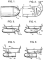
- Fig. 1 illustrates a balloon assisted dispenser 10 incorporating a linear payout waveguide leader holder 15 in accordance with the principles of the present invention. Additional information and details concerning the balloon assisted dispenser can be found in copending application EP-A-0 467 354 (a document falling within the terms of Article 54(3) EPC).
- the balloon assisted dispenser 10 is shown having a shroud or housing 11, which typically has a cylindrical shape and a cone-shaped leader holder 12 that is secured to the housing 11.
- the cone-shaped leader holder 12 has an exit aperture 14 disposed in its distal end that is adapted to allow an optical fiber waveguide (shown in Fig. 2) to exit therefrom.
- the cone shaped leader-holder 12 attaches to the aft end of the housing 11 of the balloon assisted dispenser 10.
- FIG. 2 it illustrates the interior of the balloon assisted dispenser 10 of Fig. 1.
- An optical fiber waveguide having an unjacketed portion 16 and a leader 17 comprising coiled jacketed portion is disposed within the balloon assisted dispenser 10.
- the unjacketed portion 16 is wound around a bobbin 13 disposed in the housing 11 and passes through an interior aperture 19 having a smoothly rounded contour.
- the leader 17 is coiled inside and is generally disposed in contact with the inner wall of the cone-shaped leader holder 12.
- a connector 18 is coupled to the end of the optical fiber waveguide and is secured to the leader 17.
- the exit aperture 14 of the cone-shaped leader holder 12 is large enough to allow the connector 18 to pass therethrough.
- the connector 18 is connected to a missile or vehicle (shown in Figs. 3-6) and a portion of the leader 17 extends out of the end of the leader holder 15.
- the missile for example, is launched, the coiled jacketed portion of the leader 17 acts to protect the optical fiber waveguide during the initial payout phase, wherein the waveguide is apt to experience large acceleration forces.
- the forces exerted on the unjacketed portion 16 of the waveguide are relatively minimal.
- a payout helix as small as four fiber waveguide diameters is achievable and the waveguide is protected during the high stress payout initiation phase.
- Figs. 3-6 illustrate four embodiments of single pylon launchers 20a-20d, each incorporating a dual payout initiation system 21a-21d in accordance with the principles of the present invention.
- the single pylon launchers 20a-20d are used in a missile launching system comprising a missile 22 and the launcher 20a-20d, and wherein the balloon assisted dispenser 10 of the present invention is disposed in or attached to both the missile 22 and the launcher 20a-20d of each system 21a-21d.
- the single pylon launchers 20a-20d incorporating the dual payout initiation system 21 a-21d and the balloon assisted dispensers 10 comprise the following components and structural arrangement.
- the missile 22 comprises a first balloon assisted dispenser 10a, or fuse dispenser 10a, coupled to the aft end thereof, and the missile 22 is mounted in a first launcher 20a.
- the fuse dispenser 10a is attached to the missile 22 and is configured substantially as described with reference to Figs. 1 and 2 above.
- a second balloon assisted dispenser 10b, or launcher dispenser 10b, is attached to the launcher 20a.
- the jacketed fiber optic waveguide of the fuse dispenser 10a extends out of the exit 14 and is attached along the side of the housing 11.
- the jacketed fiber optic waveguide of the launcher dispenser 10b extends out of the exit 14 and extends back along the side of the housing, and is attached thereto.
- the waveguide from the launcher dispenser 10b is connected to the waveguide of the fuse dispenser 10a via the optical connector 18.
- the fiber optic waveguide attached to the housing 11 detaches therefrom and thus initiates deployment having the waveguide disposed in the air stream.
- the arrangements of the fuse and launcher dispensers 10a, 10b are oriented such that their respective leader holders 15 are adjacent each other, as are clearly shown in the drawing figures.
- the deployment of the optical fiber waveguide from the fuse and launcher dispensers 10a, 10b of Figs. 4-6 is accomplished in a manner described above with reference to the dispenser 10 of Fig. 2.
- Figs. 3 and 4 show dual payout arrangements where the optical fiber waveguide is deployed close to the dispenser 10 during deployment.
- Fig. 3 has the optical fiber waveguide attached to the dispenser 10 prior to payout initiation.
- the two arrangements shown in Figs. 3 ad 4 have additional benefits due to the smooth outer surface the cone-shaped leader holder 12 of the balloon assisted dispenser 10.
- the single pylon launcher 20a of Fig. 3 has an L-shape and the launcher dispenser 10b is disposed adjacent the end of the L.
- the launcher dispenser 10b is oriented in a direction substantially parallel to the orientation of the missile 22.
- the fuse dispenser 10a is disposed in the aft end of the missile 22 adjacent the launcher dispenser 10b and is also oriented in a direction substantially parallel to the orientation of the missile 22.
- the launcher dispenser 10b is disposed adjacent an aft end of the launcher 20b and is oriented generally orthogonal to the orientation of the missile 22.
- the fuse dispenser 10a is disposed in the aft end of the missile 22 adjacent the launcher dispenser 10b and is oriented in a direction substantially parallel to the orientation of the missile 22.
- the launcher dispenser 10b is disposed at a forward end of the launcher 20c and is oriented orthogonal to the orientation of the missile 22.
- the fuse dispenser 10a is disposed in a forward end of the missile 22 proximate the launcher dispenser 10b and is oriented in a direction orthogonal to the orientation of the missile 22, and is generally aligned in a direction parallel to the launcher dispenser 10b.
- the launcher dispenser 10b is disposed adjacent an aft end of the launcher 20d and is oriented in a direction generally parallel to the orientation of the missile 22.
- the fuse dispenser 10a is disposed in a forward end of the missile 22 and is oriented in a direction generally orthogonal to the orientation of the missile 22.
Landscapes
- Engineering & Computer Science (AREA)
- General Engineering & Computer Science (AREA)
- Physics & Mathematics (AREA)
- Chemical & Material Sciences (AREA)
- Aviation & Aerospace Engineering (AREA)
- Combustion & Propulsion (AREA)
- General Physics & Mathematics (AREA)
- Optics & Photonics (AREA)
- Aiming, Guidance, Guns With A Light Source, Armor, Camouflage, And Targets (AREA)
- Light Guides In General And Applications Therefor (AREA)
Claims (10)
- Abgabevorrichtung (10) für eine optische Faseranordnung- mit einem Gehäuse (11),- mit einer Spule (13)- und mit einem Wellenleiter aus optischer Faser mit einem nicht ummantelten Teil (16), der um die Spule (13) gewickelt ist, und mit einem Vorlauf (17) mit einem aufgespulten, ummantelten Teil des Wellenleiters, der an den nicht ummantelten Teil (16) des Wellenleiters angeschlossen ist,
dadurch gekennzeichnet,- daß sich die Spule (13) im Gehäuse (11) befindet,- daß ein Halter (15) für den Vorlauf in Form einer Umhüllung an einem Ende des Gehäuses (11) befestigt ist, wobei der Halter (15) eine Abzugsöffnung (14) hat, die an demjenigen Ende des Halters (17) vorgesehen ist, das sich an dem dem Gehäuse (11) abgewandten Ende befindet, und wobei der Wellenleiter aus der Öffnung (14) abgezogen werden kann,- und daß der Vorlauf (17) innerhalb des Halters (15) angeordnet ist. - Abgabevorrichtung nach Anspruch 1,
dadurch gekennzeichnet,
daß der Vorlauf (17) in Kontakt mit der Innenwand des Halters (15) angeordnet ist. - Abgabevorrichtung nach Anspruch 1 oder 2,
dadurch gekennzeichnet,
daß ein Verbinder (18) vorgesehen ist, der an das Ende des Vorlaufs (17) angeschlossen ist, wobei die Abzugsöffnung (14) des Halters (15) ausreichend groß ist, so daß der Verbinder (18) dort hindurchgehen kann. - Abgabevorrichtung nach einem der vorhergehenden Patentansprüche,
dadurch gekennzeichnet,
daß der Halter (15) konusförmig ist und daß eine innere Öffnung (19) vorgesehen ist, die eine glatt gerundete Kontur hat und die zwischen dem Gehäuse (11) und dem Halter (15) angeordnet ist. - Abgabevorrichtung nach Anspruch 4,
dadurch gekennzeichnet,
daß die Abgabevorrichtung (10) ballongestützt ist. - Startsystem für Flugkörper mit einem einzigen Mast,- mit einer einmastigen Startvorrichtung (20a - 20d),- mit einer ersten Abgabevorrichtung (10a) für eine optische Faseranordnung nach einem der Patentansprüche 1 bis 5, die in oder an dem Flugkörper (22) befestigt ist,- und mit einer zweiten Abgabevorrichtung (10b) für eine optische Faseranordnung nach einem der Patentansprüche 1 bis 5, die in oder an der einmastigen Startvorrichtung (20a - 20d) befestigt ist, wobei die Vorläufe beider Abgabevorrichtungen (10a, 10b) aneinander angeschlossen sind.
- System nach Anspruch 6,
dadurch gekennzeichnet,
daß die einmastige Startvorrichtung (20a) eine L-Form hat, wobei die zweite Abgabevorrichtung (10b) sich benachbart dem Ende des L befindet und in einer Richtung im wesentlichen parallel zu der Ausrichtung des Flugkörpers (22) ausgerichtet ist, und wobei die erste Abgabevorrichtung (10a) am hinteren Ende des Flugkörpers (22) benachbart der zweiten Abgabevorrichtung (10b) angeordnet ist und in einer Richtung im wesentlichen parallel zur Ausrichtung des Flugkörpers (22) ausgerichtet ist. - System nach Anspruch 6,
dadurch gekennzeichnet,
daß die zweite Abgabevorrichtung (10b) sich benachbart dem hinteren Ende der einmastigen Startvorrichtung (20b) befindet und im wesentlichen rechtwinklig zur Ausrichtung des Flugkörpers (22) ausgerichtet ist, und daß die erste Abgabevorrichtung (10a) am hinteren Ende des Flugkörpers (22) benachbart der zweiten Abgabevorrichtung vorgesehen ist und in einer Richtung im wesentlichen parallel zur Ausrichtung des Flugkörpers (22) ausgerichtet ist. - System nach Anspruch 6,
dadurch gekennzeichnet,
daß die zweite Abgabevorrichtung (10b) am vorderen Ende der einmastigen Startvorrichtung (20c) vorgesehen ist und senkrecht zur Ausrichtung des Flugkörpers (22) ausgerichtet ist, und daß die erste Abgabevorrichtung (10a) am vorderen Ende des Flugkörpers (22) benachbart der zweiten Abgabevorrichtung (10b) angeordnet ist und in einer Richtung senkrecht zur Ausrichtung des Flugkörpers ausgerichtet ist und im wesentlichen mit der zweiten Abgabevorrichtung (10b) fluchtet. - System nach Anspruch 6,
dadurch gekennzeichnet,
daß die zweite Abgabevorrichtung (10b) benachbart dem hinteren Ende der einmastigen Startvorrichtung (20d) angeordnet ist und in einer Richtung im wesentlichen parallel zur Ausrichtung des Flugkörpers (22) ausgerichtet ist, und daß die erste Abgabevorrichtung (10a) am vorderen Ende des Flugkörpers vorgesehen ist und in einer Richtung im wesentlichen rechtwinklig zur Ausrichtung des Flugkörpers (22) ausgerichtet ist.
Applications Claiming Priority (2)
| Application Number | Priority Date | Filing Date | Title |
|---|---|---|---|
| US669243 | 1991-03-14 | ||
| US07/669,243 US5213280A (en) | 1991-03-14 | 1991-03-14 | Linear payout leader holder |
Publications (3)
| Publication Number | Publication Date |
|---|---|
| EP0503789A2 EP0503789A2 (de) | 1992-09-16 |
| EP0503789A3 EP0503789A3 (en) | 1992-10-14 |
| EP0503789B1 true EP0503789B1 (de) | 1996-04-03 |
Family
ID=24685641
Family Applications (1)
| Application Number | Title | Priority Date | Filing Date |
|---|---|---|---|
| EP92301506A Expired - Lifetime EP0503789B1 (de) | 1991-03-14 | 1992-02-24 | Lineare Abzugsvorrichtung |
Country Status (12)
| Country | Link |
|---|---|
| US (1) | US5213280A (de) |
| EP (1) | EP0503789B1 (de) |
| JP (1) | JP2550252B2 (de) |
| KR (1) | KR950012344B1 (de) |
| AU (1) | AU641310B2 (de) |
| CA (1) | CA2060001A1 (de) |
| DE (1) | DE69209552T2 (de) |
| ES (1) | ES2085563T3 (de) |
| GR (1) | GR3020444T3 (de) |
| IL (1) | IL100776A (de) |
| NO (1) | NO920730L (de) |
| TR (1) | TR26076A (de) |
Families Citing this family (4)
| Publication number | Priority date | Publication date | Assignee | Title |
|---|---|---|---|---|
| GB9501594D0 (en) * | 1995-01-27 | 1995-11-08 | British Aerospace | Tethered missile system |
| US6461480B1 (en) | 1998-02-23 | 2002-10-08 | Kao Corporation | Method of manufacturing pulp mold formed product |
| FR2792478B1 (fr) * | 1999-04-15 | 2001-07-13 | Andre Schaer | Dispositif pour la transmission d'informations entre un mobile autonome et un poste d'emission/reception |
| FR2942577B1 (fr) * | 2009-02-26 | 2014-06-13 | Andre Schaer | Dispositif pour la transmission bidirectionnelle de donnees entre un mobile energetiquement autonome et une station de controle et de commande |
Family Cites Families (13)
| Publication number | Priority date | Publication date | Assignee | Title |
|---|---|---|---|---|
| DE1258696B (de) * | 1966-07-28 | 1968-01-11 | Siemens Ag | Anordnung zum Abziehen duenner Draehte, Faeden, Adern od. dgl. |
| US4326657A (en) * | 1980-05-19 | 1982-04-27 | The United States Of America As Represented By The Secretary Of The Army | Optical fiber dispenser |
| US4860968A (en) * | 1988-04-15 | 1989-08-29 | The Boeing Company | Communication link between moving bodies |
| US4903607A (en) * | 1988-08-02 | 1990-02-27 | Optelecom, Inc. | Communication link winding and dispensing projectile |
| US5022607A (en) * | 1988-11-18 | 1991-06-11 | Hughes Aircraft Company | Bend limiting stiff leader and retainer system |
| FR2644764B1 (fr) * | 1989-03-22 | 1991-07-05 | Aerospatiale | Bobine de fibre optique de grande longueur utilisable sur un missile filoguide |
| US5044573A (en) * | 1989-06-23 | 1991-09-03 | Hughes Aircraft Company | Rotating drum filament dispenser |
| US5014930A (en) * | 1989-06-23 | 1991-05-14 | Hughes Aircraft Company | Missile filament dispensing arrangement |
| US4991793A (en) * | 1989-06-26 | 1991-02-12 | Optelecom, Inc. | Optical cable payoff system |
| US4974793A (en) * | 1989-12-15 | 1990-12-04 | The Boeing Company | Tapered chamber dispensing of optical fiber |
| US4979793A (en) | 1990-02-21 | 1990-12-25 | Amp Incorporated | Optical simulator with loop-back attenuator and adjustable plunger mechanism |
| US5005930A (en) * | 1990-02-23 | 1991-04-09 | Hughes Aircraft Company | Multi-directional payout fiber optic canister |
| US5031982A (en) * | 1990-05-23 | 1991-07-16 | Hughes Aircraft Company | Flexible payout duct |
-
1991
- 1991-03-14 US US07/669,243 patent/US5213280A/en not_active Expired - Lifetime
-
1992
- 1992-01-24 CA CA002060001A patent/CA2060001A1/en not_active Abandoned
- 1992-01-27 IL IL100776A patent/IL100776A/xx not_active IP Right Cessation
- 1992-02-24 DE DE69209552T patent/DE69209552T2/de not_active Expired - Lifetime
- 1992-02-24 EP EP92301506A patent/EP0503789B1/de not_active Expired - Lifetime
- 1992-02-24 NO NO92920730A patent/NO920730L/no unknown
- 1992-02-24 ES ES92301506T patent/ES2085563T3/es not_active Expired - Lifetime
- 1992-03-10 JP JP4051913A patent/JP2550252B2/ja not_active Expired - Lifetime
- 1992-03-12 TR TR92/0295A patent/TR26076A/xx unknown
- 1992-03-13 AU AU12902/92A patent/AU641310B2/en not_active Ceased
- 1992-03-13 KR KR1019920004142A patent/KR950012344B1/ko not_active Expired - Lifetime
-
1996
- 1996-07-02 GR GR960401818T patent/GR3020444T3/el unknown
Also Published As
| Publication number | Publication date |
|---|---|
| JP2550252B2 (ja) | 1996-11-06 |
| DE69209552D1 (de) | 1996-05-09 |
| US5213280A (en) | 1993-05-25 |
| KR950012344B1 (ko) | 1995-10-17 |
| CA2060001A1 (en) | 1992-09-15 |
| NO920730L (no) | 1992-09-15 |
| EP0503789A3 (en) | 1992-10-14 |
| JPH0571900A (ja) | 1993-03-23 |
| AU641310B2 (en) | 1993-09-16 |
| GR3020444T3 (en) | 1996-10-31 |
| DE69209552T2 (de) | 1996-09-19 |
| KR920018448A (ko) | 1992-10-22 |
| ES2085563T3 (es) | 1996-06-01 |
| NO920730D0 (no) | 1992-02-24 |
| AU1290292A (en) | 1992-09-17 |
| IL100776A (en) | 1997-06-10 |
| EP0503789A2 (de) | 1992-09-16 |
| TR26076A (tr) | 1994-12-15 |
Similar Documents
| Publication | Publication Date | Title |
|---|---|---|
| US4860968A (en) | Communication link between moving bodies | |
| US6683555B2 (en) | Fast deploy, retrievable and reusable airborne counter-measure system | |
| JP2550224B2 (ja) | 多方向繰出し光ファイバキャニスタ | |
| US5564649A (en) | Apparatus for the remote control of missiles or torpedoes | |
| US5167382A (en) | Inside payout optical fiber canister having reduced adhesive in the optical fiber pack | |
| EP0503789B1 (de) | Lineare Abzugsvorrichtung | |
| JPH04229806A (ja) | フレキシブル繰出しダクト | |
| US4974793A (en) | Tapered chamber dispensing of optical fiber | |
| US5189253A (en) | Filament dispenser | |
| US5520346A (en) | Reel payout system | |
| JPH04251199A (ja) | 開放砲尾の高温噴射ガスにより発射される光ファイバの繰出し装置 | |
| AU2002356557B2 (en) | Method and apparatus for the recovery of bodies towed from moving vehicles | |
| US5014930A (en) | Missile filament dispensing arrangement | |
| AU2002356557A1 (en) | Method and apparatus for the recovery of bodies towed from moving vehicles | |
| AU2002356559A1 (en) | Compact deployment and retrieval system for a towed decoy utilizing a single cable employing fiber optics | |
| JPH03502360A (ja) | 湾曲を制限する堅牢なリーダおよび保持システム | |
| US5509621A (en) | Mechanism for high speed linear payout of mono-filament strand | |
| US5040744A (en) | Missile filament dispensing arrangement | |
| US5226615A (en) | Air damped linear optical fiber dispenser | |
| AU2002353797A1 (en) | Fast deploy, retrievable and reusable airborne, counter-measure system | |
| GB2434192A (en) | Missile launch apparatus |
Legal Events
| Date | Code | Title | Description |
|---|---|---|---|
| PUAI | Public reference made under article 153(3) epc to a published international application that has entered the european phase |
Free format text: ORIGINAL CODE: 0009012 |
|
| PUAL | Search report despatched |
Free format text: ORIGINAL CODE: 0009013 |
|
| AK | Designated contracting states |
Kind code of ref document: A2 Designated state(s): CH DE ES FR GB GR IT LI NL SE |
|
| AK | Designated contracting states |
Kind code of ref document: A3 Designated state(s): CH DE ES FR GB GR IT LI NL SE |
|
| 17P | Request for examination filed |
Effective date: 19930319 |
|
| 17Q | First examination report despatched |
Effective date: 19941118 |
|
| GRAA | (expected) grant |
Free format text: ORIGINAL CODE: 0009210 |
|
| AK | Designated contracting states |
Kind code of ref document: B1 Designated state(s): CH DE ES FR GB GR IT LI NL SE |
|
| PG25 | Lapsed in a contracting state [announced via postgrant information from national office to epo] |
Ref country code: GR Free format text: LAPSE BECAUSE OF FAILURE TO SUBMIT A TRANSLATION OF THE DESCRIPTION OR TO PAY THE FEE WITHIN THE PRESCRIBED TIME-LIMIT Effective date: 19960403 |
|
| REG | Reference to a national code |
Ref country code: CH Ref legal event code: NV Representative=s name: ISLER & PEDRAZZINI AG PATENTANWAELTE |
|
| ITF | It: translation for a ep patent filed | ||
| REF | Corresponds to: |
Ref document number: 69209552 Country of ref document: DE Date of ref document: 19960509 |
|
| REG | Reference to a national code |
Ref country code: ES Ref legal event code: FG2A Ref document number: 2085563 Country of ref document: ES Kind code of ref document: T3 |
|
| ET | Fr: translation filed | ||
| REG | Reference to a national code |
Ref country code: GR Ref legal event code: FG4A Free format text: 3020444 |
|
| PLBE | No opposition filed within time limit |
Free format text: ORIGINAL CODE: 0009261 |
|
| PG25 | Lapsed in a contracting state [announced via postgrant information from national office to epo] |
Ref country code: SE Effective date: 19970225 Ref country code: ES Free format text: THE PATENT HAS BEEN ANNULLED BY A DECISION OF A NATIONAL AUTHORITY Effective date: 19970225 |
|
| PG25 | Lapsed in a contracting state [announced via postgrant information from national office to epo] |
Ref country code: CH Effective date: 19970228 Ref country code: LI Effective date: 19970228 |
|
| 26N | No opposition filed | ||
| PG25 | Lapsed in a contracting state [announced via postgrant information from national office to epo] |
Ref country code: NL Effective date: 19970901 |
|
| REG | Reference to a national code |
Ref country code: GR Ref legal event code: MM2A Free format text: 3020444 |
|
| REG | Reference to a national code |
Ref country code: CH Ref legal event code: PL |
|
| EUG | Se: european patent has lapsed |
Ref document number: 92301506.9 |
|
| NLV4 | Nl: lapsed or anulled due to non-payment of the annual fee |
Effective date: 19970901 |
|
| REG | Reference to a national code |
Ref country code: GB Ref legal event code: 732E |
|
| REG | Reference to a national code |
Ref country code: FR Ref legal event code: CD Ref country code: FR Ref legal event code: TP Ref country code: FR Ref legal event code: CA |
|
| REG | Reference to a national code |
Ref country code: GB Ref legal event code: IF02 |
|
| REG | Reference to a national code |
Ref country code: ES Ref legal event code: FD2A Effective date: 20020204 |
|
| PG25 | Lapsed in a contracting state [announced via postgrant information from national office to epo] |
Ref country code: IT Free format text: LAPSE BECAUSE OF NON-PAYMENT OF DUE FEES Effective date: 20050224 |
|
| PGFP | Annual fee paid to national office [announced via postgrant information from national office to epo] |
Ref country code: FR Payment date: 20110218 Year of fee payment: 20 Ref country code: DE Payment date: 20110216 Year of fee payment: 20 |
|
| PGFP | Annual fee paid to national office [announced via postgrant information from national office to epo] |
Ref country code: GB Payment date: 20110223 Year of fee payment: 20 |
|
| REG | Reference to a national code |
Ref country code: DE Ref legal event code: R071 Ref document number: 69209552 Country of ref document: DE |
|
| REG | Reference to a national code |
Ref country code: DE Ref legal event code: R071 Ref document number: 69209552 Country of ref document: DE |
|
| REG | Reference to a national code |
Ref country code: GB Ref legal event code: PE20 Expiry date: 20120223 |
|
| PG25 | Lapsed in a contracting state [announced via postgrant information from national office to epo] |
Ref country code: DE Free format text: LAPSE BECAUSE OF EXPIRATION OF PROTECTION Effective date: 20120225 |
|
| PG25 | Lapsed in a contracting state [announced via postgrant information from national office to epo] |
Ref country code: GB Free format text: LAPSE BECAUSE OF EXPIRATION OF PROTECTION Effective date: 20120223 |