EP0503146B1 - Tuyau plat de tirage pour gaz de chauffage pour chaudière à condensation - Google Patents
Tuyau plat de tirage pour gaz de chauffage pour chaudière à condensation Download PDFInfo
- Publication number
- EP0503146B1 EP0503146B1 EP91120880A EP91120880A EP0503146B1 EP 0503146 B1 EP0503146 B1 EP 0503146B1 EP 91120880 A EP91120880 A EP 91120880A EP 91120880 A EP91120880 A EP 91120880A EP 0503146 B1 EP0503146 B1 EP 0503146B1
- Authority
- EP
- European Patent Office
- Prior art keywords
- corrugated
- impressions
- heating gas
- flow
- Prior art date
- Legal status (The legal status is an assumption and is not a legal conclusion. Google has not performed a legal analysis and makes no representation as to the accuracy of the status listed.)
- Expired - Lifetime
Links
- 238000010438 heat treatment Methods 0.000 title claims abstract description 24
- XLYOFNOQVPJJNP-UHFFFAOYSA-N water Substances O XLYOFNOQVPJJNP-UHFFFAOYSA-N 0.000 claims abstract description 11
- 238000003466 welding Methods 0.000 claims 3
- 239000002184 metal Substances 0.000 abstract description 13
- 239000007789 gas Substances 0.000 description 21
- 238000011161 development Methods 0.000 description 6
- 230000018109 developmental process Effects 0.000 description 6
- 238000004049 embossing Methods 0.000 description 6
- 230000015572 biosynthetic process Effects 0.000 description 2
- 238000002485 combustion reaction Methods 0.000 description 2
- 239000012141 concentrate Substances 0.000 description 1
- 239000002737 fuel gas Substances 0.000 description 1
- 239000003517 fume Substances 0.000 description 1
- 238000009434 installation Methods 0.000 description 1
- 238000004519 manufacturing process Methods 0.000 description 1
- 238000013021 overheating Methods 0.000 description 1
- 239000002244 precipitate Substances 0.000 description 1
- 230000000630 rising effect Effects 0.000 description 1
- 238000011144 upstream manufacturing Methods 0.000 description 1
Images


Classifications
-
- F—MECHANICAL ENGINEERING; LIGHTING; HEATING; WEAPONS; BLASTING
- F28—HEAT EXCHANGE IN GENERAL
- F28F—DETAILS OF HEAT-EXCHANGE AND HEAT-TRANSFER APPARATUS, OF GENERAL APPLICATION
- F28F3/00—Plate-like or laminated elements; Assemblies of plate-like or laminated elements
- F28F3/02—Elements or assemblies thereof with means for increasing heat-transfer area, e.g. with fins, with recesses, with corrugations
- F28F3/04—Elements or assemblies thereof with means for increasing heat-transfer area, e.g. with fins, with recesses, with corrugations the means being integral with the element
- F28F3/042—Elements or assemblies thereof with means for increasing heat-transfer area, e.g. with fins, with recesses, with corrugations the means being integral with the element in the form of local deformations of the element
- F28F3/046—Elements or assemblies thereof with means for increasing heat-transfer area, e.g. with fins, with recesses, with corrugations the means being integral with the element in the form of local deformations of the element the deformations being linear, e.g. corrugations
-
- F—MECHANICAL ENGINEERING; LIGHTING; HEATING; WEAPONS; BLASTING
- F24—HEATING; RANGES; VENTILATING
- F24H—FLUID HEATERS, e.g. WATER OR AIR HEATERS, HAVING HEAT-GENERATING MEANS, e.g. HEAT PUMPS, IN GENERAL
- F24H1/00—Water heaters, e.g. boilers, continuous-flow heaters or water-storage heaters
- F24H1/22—Water heaters other than continuous-flow or water-storage heaters, e.g. water heaters for central heating
- F24H1/24—Water heaters other than continuous-flow or water-storage heaters, e.g. water heaters for central heating with water mantle surrounding the combustion chamber or chambers
- F24H1/26—Water heaters other than continuous-flow or water-storage heaters, e.g. water heaters for central heating with water mantle surrounding the combustion chamber or chambers the water mantle forming an integral body
- F24H1/28—Water heaters other than continuous-flow or water-storage heaters, e.g. water heaters for central heating with water mantle surrounding the combustion chamber or chambers the water mantle forming an integral body including one or more furnace or fire tubes
- F24H1/287—Water heaters other than continuous-flow or water-storage heaters, e.g. water heaters for central heating with water mantle surrounding the combustion chamber or chambers the water mantle forming an integral body including one or more furnace or fire tubes with the fire tubes arranged in line with the combustion chamber
-
- F—MECHANICAL ENGINEERING; LIGHTING; HEATING; WEAPONS; BLASTING
- F24—HEATING; RANGES; VENTILATING
- F24H—FLUID HEATERS, e.g. WATER OR AIR HEATERS, HAVING HEAT-GENERATING MEANS, e.g. HEAT PUMPS, IN GENERAL
- F24H8/00—Fluid heaters characterised by means for extracting latent heat from flue gases by means of condensation
-
- F—MECHANICAL ENGINEERING; LIGHTING; HEATING; WEAPONS; BLASTING
- F28—HEAT EXCHANGE IN GENERAL
- F28D—HEAT-EXCHANGE APPARATUS, NOT PROVIDED FOR IN ANOTHER SUBCLASS, IN WHICH THE HEAT-EXCHANGE MEDIA DO NOT COME INTO DIRECT CONTACT
- F28D9/00—Heat-exchange apparatus having stationary plate-like or laminated conduit assemblies for both heat-exchange media, the media being in contact with different sides of a conduit wall
- F28D9/0031—Heat-exchange apparatus having stationary plate-like or laminated conduit assemblies for both heat-exchange media, the media being in contact with different sides of a conduit wall the conduits for one heat-exchange medium being formed by paired plates touching each other
-
- Y—GENERAL TAGGING OF NEW TECHNOLOGICAL DEVELOPMENTS; GENERAL TAGGING OF CROSS-SECTIONAL TECHNOLOGIES SPANNING OVER SEVERAL SECTIONS OF THE IPC; TECHNICAL SUBJECTS COVERED BY FORMER USPC CROSS-REFERENCE ART COLLECTIONS [XRACs] AND DIGESTS
- Y02—TECHNOLOGIES OR APPLICATIONS FOR MITIGATION OR ADAPTATION AGAINST CLIMATE CHANGE
- Y02B—CLIMATE CHANGE MITIGATION TECHNOLOGIES RELATED TO BUILDINGS, e.g. HOUSING, HOUSE APPLIANCES OR RELATED END-USER APPLICATIONS
- Y02B30/00—Energy efficient heating, ventilation or air conditioning [HVAC]
Definitions
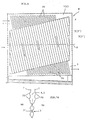
- the channels By designing the channels in this way, the heating gases flowing into the inflow channel 4 are better distributed in the channels going downwards from there to the outflow channel 5 (the resistance is greater at the front than at the rear), the thermal load on the exchange surface is evened out, overheating and vapor bubble formation are prevented and thus the overall heat transfer is improved.
- This better distribution is also of particular importance when boilers equipped with such pockets are equipped with burners that can be operated with graded or modulating control as required.
Landscapes
- Engineering & Computer Science (AREA)
- Physics & Mathematics (AREA)
- Thermal Sciences (AREA)
- Mechanical Engineering (AREA)
- General Engineering & Computer Science (AREA)
- Chemical & Material Sciences (AREA)
- Combustion & Propulsion (AREA)
- Heat-Exchange Devices With Radiators And Conduit Assemblies (AREA)
- Cookers (AREA)
- Gas Separation By Absorption (AREA)
- Shaping Metal By Deep-Drawing, Or The Like (AREA)
- Bag Frames (AREA)
Claims (7)
- Poche de tirage de gaz de chauffage, en particulier pour chaudière de chauffage à condensation, constituée par deux découpes de tôle minces (1, 2) qui s'étendent dans des plans parallèles, qui forment la poche (T) fermée côté eau (WS), qui sont pourvues chacune d'estampages d'ondulations (3) parallèles les uns aux autres, les estampages d'ondulations (3) de l'une des découpes (1) étant inclinés par rapport aux estampages d'ondulations (3′) de l'autre découpe (2),
caractérisée en ce
que la poche (T) est pourvue d'un canal supérieur d'afflux (4) qui se resserre en forme de clavette vers le côté écoulement (A) et d'un canal inférieur d'écoulement (5) qui s'élargit en forme de clavette vers le côté écoulement (A) et que les estampages d'ondulations (3, 3′) sont placés entre les deux canaux (4, 5) dans les découpes de tôle (1, 2) qui forment les poches (T) en étant substantiellement perpendiculaires à l'axe longitudinal des poches (6) mais en étant orientés les uns par rapport aux autres avec une inclinaison différente. - Poche de tirage de gaz de chauffage selon la revendication 1,
caractérisée en ce
que les estampages d'ondulations (3′) de la seconde découpe (2) sont inclinés par rapport à la verticale (V) de 0 à 5°, de préférence de 2,5°, et les estampages d'ondulations (3) de la première découpe (1) sont inclinés avec la même orientation d'inclinaison mais avec une différence d'inclinaison par rapport aux estampages d'ondulations (3′) de la seconde découpe (2) de 15° maximum, de préférence de 7,5°, vers le canal d'écoulement (5) dans le sens de l'écoulement. - Poche de tirage de gaz de chauffage selon la revendication 1 ou 2,
caractérisée en ce
que les deux découpes (1, 2) sont configurées en étant assemblées en une découpe en une pièce (Z), la bande centrale (7) qui est recourbée et sans ondulations formant la délimitation inférieure de la poche (T) qui est fermée en haut le long de bords recourbés (8) par une soudure longitudinale (9). - Poche de tirage de gaz de chauffage selon la revendication 2 ou 3,
caractérisée en ce
que les bords recourbés (8) sont pourvus de bords (8′) contigus coudés en plus dans la section de tirage (Q) et que la soudure longitudinale (9) est placée dans le gousset formé par les bords supplémentaires (8′). - Poche de tirage de gaz de chauffage selon l'une des revendications 1 à 4,
caractérisée en ce
que des barrettes (11) coudées deux fois sont placées côté afflux et côté écoulement sur les découpes (1, 2) le long de leurs bords verticaux (10) pour des poches (T) respectivement voisines, raccordées par la soudure longitudinale (12). - Poche de tirage de gaz de chauffage, en particulier selon l'une des revendications 1 à 5,
caractérisée en ce
que la division des estampages d'ondulations (3, 3′) augmente en direction du côté écoulement si bien que les sections des canaux délimités par les estampages d'ondulations (3, 3′) des deux découpes de tôle (1, 2) deviennent respectivement plus grandes du côté afflux (AN) de la poche au côté écoulement (A) de la poche mais que les sections de chaque canal sont configurées en étant constantes sur la longueur de son extension. - Poche de tirage de gaz de chauffage selon l'une des revendications 1 à 6,
caractérisée en ce
que des estampages d'ondulations (20) sont placés dans les découpes de tôle (1, 2), et ce dans la zone des canaux en forme de clavette (4, 5) également et substantiellement avec la même orientation d'inclinaison mais que ceux-ci sont estampés vers le côté eau.
Applications Claiming Priority (4)
| Application Number | Priority Date | Filing Date | Title |
|---|---|---|---|
| DE4107948A DE4107948C1 (en) | 1991-03-13 | 1991-03-13 | Heating gas flue pocket of two sheet metal blanks - top, conically tapering inlet duct, and conically widening, lower outlet duct |
| DE4107948 | 1991-03-13 | ||
| DE4117778A DE4117778C1 (fr) | 1991-03-13 | 1991-05-31 | |
| DE4117778 | 1991-05-31 |
Publications (2)
| Publication Number | Publication Date |
|---|---|
| EP0503146A1 EP0503146A1 (fr) | 1992-09-16 |
| EP0503146B1 true EP0503146B1 (fr) | 1994-06-22 |
Family
ID=25901774
Family Applications (1)
| Application Number | Title | Priority Date | Filing Date |
|---|---|---|---|
| EP91120880A Expired - Lifetime EP0503146B1 (fr) | 1991-03-13 | 1991-12-05 | Tuyau plat de tirage pour gaz de chauffage pour chaudière à condensation |
Country Status (4)
| Country | Link |
|---|---|
| EP (1) | EP0503146B1 (fr) |
| AT (1) | ATE107758T1 (fr) |
| DE (2) | DE4117778C1 (fr) |
| ES (1) | ES2056557T3 (fr) |
Families Citing this family (2)
| Publication number | Priority date | Publication date | Assignee | Title |
|---|---|---|---|---|
| DE9309771U1 (de) * | 1993-07-01 | 1993-08-26 | Viessmann Werke Gmbh & Co, 35108 Allendorf | Heizgaszug |
| DE19833338A1 (de) * | 1998-07-24 | 2000-01-27 | Modine Mfg Co | Wärmetauscher, insbesondere Abgaswärmetauscher |
Family Cites Families (3)
| Publication number | Priority date | Publication date | Assignee | Title |
|---|---|---|---|---|
| EP0016915B1 (fr) * | 1979-03-16 | 1983-01-26 | Buderus Aktiengesellschaft | Chaudière de chauffage central |
| AT388446B (de) * | 1986-08-29 | 1989-06-26 | Fischer Gerhard | Plattenwaermeaustauscher |
| DE9106654U1 (de) * | 1991-05-31 | 1991-07-25 | Vießmann, Hans, Dr.h.c., 3559 Battenberg | Heizkessel |
-
1991
- 1991-05-31 DE DE4117778A patent/DE4117778C1/de not_active Expired - Lifetime
- 1991-12-05 ES ES91120880T patent/ES2056557T3/es not_active Expired - Lifetime
- 1991-12-05 EP EP91120880A patent/EP0503146B1/fr not_active Expired - Lifetime
- 1991-12-05 AT AT91120880T patent/ATE107758T1/de not_active IP Right Cessation
- 1991-12-05 DE DE59102020T patent/DE59102020D1/de not_active Expired - Fee Related
Also Published As
| Publication number | Publication date |
|---|---|
| DE59102020D1 (de) | 1994-07-28 |
| ES2056557T3 (es) | 1994-10-01 |
| EP0503146A1 (fr) | 1992-09-16 |
| DE4117778C1 (fr) | 1992-09-10 |
| ATE107758T1 (de) | 1994-07-15 |
Similar Documents
| Publication | Publication Date | Title |
|---|---|---|
| DE19722097A1 (de) | Wärmeübertrager sowie Wärmeübertrageranordnung für ein Kraftfahrzeug | |
| DE2613186C3 (de) | Heizungskessel für flussige oder gasformige Brennstoffe | |
| DE69903895T2 (de) | Wärmetauscher | |
| EP0230594B1 (fr) | Chaudière à condensation | |
| EP0503146B1 (fr) | Tuyau plat de tirage pour gaz de chauffage pour chaudière à condensation | |
| EP0177904B1 (fr) | Dispositif pour l'échange de chaleur entre deux gaz en flux croisé | |
| DE4232880A1 (de) | Dampferzeuger | |
| DE4107948C1 (en) | Heating gas flue pocket of two sheet metal blanks - top, conically tapering inlet duct, and conically widening, lower outlet duct | |
| EP0321667B1 (fr) | Chaudière | |
| EP0254760B1 (fr) | Appareil de chauffage de local pour petits locaux | |
| EP0915304B1 (fr) | Chaudière à trois passages | |
| EP0164098A2 (fr) | Echangeur de chaleur | |
| EP0120435B1 (fr) | Structure du parcours du gaz de chauffage dans une chaudière de chauffage | |
| DE4107947C1 (en) | Boiler with flat sheets - has corrugations running in different directions to give rapid heat transfer | |
| DE3205121C2 (de) | Heizungskessel | |
| DE19505235B4 (de) | Brennwertkessel | |
| EP0467250A1 (fr) | Tuyau plat de tirage pour gaz de chauffage | |
| EP0045491A1 (fr) | Poêle pour chauffer des petits locaux | |
| AT392025B (de) | Blechzuschnitt fuer die ausbildung eines in ein aussenrohr, insbesondere heizgaszugrohr, einsetzbaren innenrohres | |
| DE2753841C2 (fr) | ||
| DE2910968C2 (de) | Heizkörper mit einem kastenartigen Gehäuse | |
| DE4229146C1 (de) | Gasheizkessel | |
| DE2819145C2 (de) | Kamineinsatz | |
| DE69003657T2 (de) | Wärmetauscheinheit für Lufterhitzer. | |
| EP0430061B1 (fr) | Chaudière de chauffage |
Legal Events
| Date | Code | Title | Description |
|---|---|---|---|
| PUAI | Public reference made under article 153(3) epc to a published international application that has entered the european phase |
Free format text: ORIGINAL CODE: 0009012 |
|
| AK | Designated contracting states |
Kind code of ref document: A1 Designated state(s): AT BE CH DE ES FR GB IT LI LU |
|
| 17P | Request for examination filed |
Effective date: 19921217 |
|
| 17Q | First examination report despatched |
Effective date: 19931005 |
|
| ITF | It: translation for a ep patent filed | ||
| GRAA | (expected) grant |
Free format text: ORIGINAL CODE: 0009210 |
|
| RAP1 | Party data changed (applicant data changed or rights of an application transferred) |
Owner name: VIESSMANN, HANS, DR. |
|
| AK | Designated contracting states |
Kind code of ref document: B1 Designated state(s): AT BE CH DE ES FR GB IT LI LU |
|
| REF | Corresponds to: |
Ref document number: 107758 Country of ref document: AT Date of ref document: 19940715 Kind code of ref document: T |
|
| ET | Fr: translation filed | ||
| GBT | Gb: translation of ep patent filed (gb section 77(6)(a)/1977) |
Effective date: 19940628 |
|
| REF | Corresponds to: |
Ref document number: 59102020 Country of ref document: DE Date of ref document: 19940728 |
|
| REG | Reference to a national code |
Ref country code: ES Ref legal event code: FG2A Ref document number: 2056557 Country of ref document: ES Kind code of ref document: T3 |
|
| PLBE | No opposition filed within time limit |
Free format text: ORIGINAL CODE: 0009261 |
|
| STAA | Information on the status of an ep patent application or granted ep patent |
Free format text: STATUS: NO OPPOSITION FILED WITHIN TIME LIMIT |
|
| 26N | No opposition filed | ||
| PGFP | Annual fee paid to national office [announced via postgrant information from national office to epo] |
Ref country code: GB Payment date: 19981127 Year of fee payment: 8 |
|
| PGFP | Annual fee paid to national office [announced via postgrant information from national office to epo] |
Ref country code: ES Payment date: 19981204 Year of fee payment: 8 |
|
| PGFP | Annual fee paid to national office [announced via postgrant information from national office to epo] |
Ref country code: LU Payment date: 19981214 Year of fee payment: 8 |
|
| PGFP | Annual fee paid to national office [announced via postgrant information from national office to epo] |
Ref country code: CH Payment date: 19981215 Year of fee payment: 8 Ref country code: BE Payment date: 19981215 Year of fee payment: 8 |
|
| PGFP | Annual fee paid to national office [announced via postgrant information from national office to epo] |
Ref country code: DE Payment date: 19981224 Year of fee payment: 8 |
|
| PGFP | Annual fee paid to national office [announced via postgrant information from national office to epo] |
Ref country code: FR Payment date: 19981229 Year of fee payment: 8 Ref country code: AT Payment date: 19981229 Year of fee payment: 8 |
|
| PG25 | Lapsed in a contracting state [announced via postgrant information from national office to epo] |
Ref country code: LU Free format text: LAPSE BECAUSE OF NON-PAYMENT OF DUE FEES Effective date: 19991205 Ref country code: GB Free format text: LAPSE BECAUSE OF NON-PAYMENT OF DUE FEES Effective date: 19991205 Ref country code: AT Free format text: LAPSE BECAUSE OF NON-PAYMENT OF DUE FEES Effective date: 19991205 |
|
| PG25 | Lapsed in a contracting state [announced via postgrant information from national office to epo] |
Ref country code: LI Free format text: LAPSE BECAUSE OF NON-PAYMENT OF DUE FEES Effective date: 19991231 Ref country code: CH Free format text: LAPSE BECAUSE OF NON-PAYMENT OF DUE FEES Effective date: 19991231 Ref country code: BE Free format text: LAPSE BECAUSE OF NON-PAYMENT OF DUE FEES Effective date: 19991231 |
|
| BERE | Be: lapsed |
Owner name: VIESSMANN HANS Effective date: 19991231 |
|
| GBPC | Gb: european patent ceased through non-payment of renewal fee |
Effective date: 19991205 |
|
| PG25 | Lapsed in a contracting state [announced via postgrant information from national office to epo] |
Ref country code: FR Free format text: LAPSE BECAUSE OF NON-PAYMENT OF DUE FEES Effective date: 20000831 |
|
| PG25 | Lapsed in a contracting state [announced via postgrant information from national office to epo] |
Ref country code: DE Free format text: LAPSE BECAUSE OF NON-PAYMENT OF DUE FEES Effective date: 20001003 |
|
| REG | Reference to a national code |
Ref country code: FR Ref legal event code: ST |
|
| PG25 | Lapsed in a contracting state [announced via postgrant information from national office to epo] |
Ref country code: ES Free format text: LAPSE BECAUSE OF NON-PAYMENT OF DUE FEES Effective date: 20001206 |
|
| REG | Reference to a national code |
Ref country code: ES Ref legal event code: FD2A Effective date: 20010113 |
|
| PG25 | Lapsed in a contracting state [announced via postgrant information from national office to epo] |
Ref country code: IT Free format text: LAPSE BECAUSE OF NON-PAYMENT OF DUE FEES;WARNING: LAPSES OF ITALIAN PATENTS WITH EFFECTIVE DATE BEFORE 2007 MAY HAVE OCCURRED AT ANY TIME BEFORE 2007. THE CORRECT EFFECTIVE DATE MAY BE DIFFERENT FROM THE ONE RECORDED. Effective date: 20051205 |