EP0502606A2 - Method for molding a laminate - Google Patents
Method for molding a laminate Download PDFInfo
- Publication number
- EP0502606A2 EP0502606A2 EP92300625A EP92300625A EP0502606A2 EP 0502606 A2 EP0502606 A2 EP 0502606A2 EP 92300625 A EP92300625 A EP 92300625A EP 92300625 A EP92300625 A EP 92300625A EP 0502606 A2 EP0502606 A2 EP 0502606A2
- Authority
- EP
- European Patent Office
- Prior art keywords
- surface layer
- deformable surface
- edge portion
- undersurface
- mold member
- Prior art date
- Legal status (The legal status is an assumption and is not a legal conclusion. Google has not performed a legal analysis and makes no representation as to the accuracy of the status listed.)
- Withdrawn
Links
Images

Classifications
-
- B—PERFORMING OPERATIONS; TRANSPORTING
- B29—WORKING OF PLASTICS; WORKING OF SUBSTANCES IN A PLASTIC STATE IN GENERAL
- B29C—SHAPING OR JOINING OF PLASTICS; SHAPING OF MATERIAL IN A PLASTIC STATE, NOT OTHERWISE PROVIDED FOR; AFTER-TREATMENT OF THE SHAPED PRODUCTS, e.g. REPAIRING
- B29C45/00—Injection moulding, i.e. forcing the required volume of moulding material through a nozzle into a closed mould; Apparatus therefor
- B29C45/14—Injection moulding, i.e. forcing the required volume of moulding material through a nozzle into a closed mould; Apparatus therefor incorporating preformed parts or layers, e.g. injection moulding around inserts or for coating articles
- B29C45/1418—Injection moulding, i.e. forcing the required volume of moulding material through a nozzle into a closed mould; Apparatus therefor incorporating preformed parts or layers, e.g. injection moulding around inserts or for coating articles the inserts being deformed or preformed, e.g. by the injection pressure
- B29C45/14196—Injection moulding, i.e. forcing the required volume of moulding material through a nozzle into a closed mould; Apparatus therefor incorporating preformed parts or layers, e.g. injection moulding around inserts or for coating articles the inserts being deformed or preformed, e.g. by the injection pressure the inserts being positioned around an edge of the injected part
-
- B—PERFORMING OPERATIONS; TRANSPORTING
- B29—WORKING OF PLASTICS; WORKING OF SUBSTANCES IN A PLASTIC STATE IN GENERAL
- B29C—SHAPING OR JOINING OF PLASTICS; SHAPING OF MATERIAL IN A PLASTIC STATE, NOT OTHERWISE PROVIDED FOR; AFTER-TREATMENT OF THE SHAPED PRODUCTS, e.g. REPAIRING
- B29C70/00—Shaping composites, i.e. plastics material comprising reinforcements, fillers or preformed parts, e.g. inserts
- B29C70/68—Shaping composites, i.e. plastics material comprising reinforcements, fillers or preformed parts, e.g. inserts by incorporating or moulding on preformed parts, e.g. inserts or layers, e.g. foam blocks
- B29C70/681—Component parts, details or accessories; Auxiliary operations
- B29C70/683—Pretreatment of the preformed part, e.g. insert
-
- B—PERFORMING OPERATIONS; TRANSPORTING
- B29—WORKING OF PLASTICS; WORKING OF SUBSTANCES IN A PLASTIC STATE IN GENERAL
- B29C—SHAPING OR JOINING OF PLASTICS; SHAPING OF MATERIAL IN A PLASTIC STATE, NOT OTHERWISE PROVIDED FOR; AFTER-TREATMENT OF THE SHAPED PRODUCTS, e.g. REPAIRING
- B29C45/00—Injection moulding, i.e. forcing the required volume of moulding material through a nozzle into a closed mould; Apparatus therefor
- B29C45/14—Injection moulding, i.e. forcing the required volume of moulding material through a nozzle into a closed mould; Apparatus therefor incorporating preformed parts or layers, e.g. injection moulding around inserts or for coating articles
- B29C2045/1486—Details, accessories and auxiliary operations
- B29C2045/1495—Coating undercut inserts
Definitions
- the present invention relates generally to the manufacture of a laminate and, more particularly, to a laminate wherein the edges of a deformable surface layer are folded under and molded in a total bonded relationship to the edges of a plastic support layer during the injection of the plastic material.
- a total bonded relationship can be achieved by placing the deformable surface layer into the mold unit and injecting a plastic material to form a plastic support layer which is molded in a total bonded relationship with the deformable surface layer.
- a problem with this method of molding the plastic support layer to the deformable surface layer is that the edges of the deformable surface layer do not bond to the bottom of the plastic support layer because it has not been possible to pre-fold them accordingly so as to bond to the bottom of the injected plastic material.
- the securement between the folded edge portion and the undersurface of the deformable surface layer may be released upon injection of the plastic.
- the bonded edges improve the securement between the deformable surface layer and the plastic support layer while giving the laminate a "finished" appearance without tacks or staples.
- a process of forming a laminate 10 (Figs. 5 and 6) is illustrated wherein edges 12 of a deformable surface layer 14 are folded over and releasably secured (Fig. 1) prior to the deformable surface layer 14 being placed into a mold unit 16 in which a plastic is injected to form a support layer 18 for the laminate 10
- the process is suitable for materials such as cloth, carpet, film, foil, paper or any other material which is deformable and below which it is desirable to form a plastic support layer 18. It is to be understood that the terms “bottom”, “top”, “above”, “below”, “over” and “under” are relative to the laminate as it would be seen in normal use.
- the deformable surface layer 14 is provided in which the edge portion 12 located along at least a partial perimeter of the deformable surface layer 14 is folded under (Fig. 1).
- a releasable adhesive is placed at intermittent points 20 along the perimeter of the deformable surface layer 14 between the folded edge portion 12 and an undersurface 22 of the deformable surface layer 14.
- the folded edge portion 12 is then pressed against the undersurface 22 of the deformable surface layer 14 into adhesive contact.
- the adhesive be of the type which is releasable after time.
- the plastic injection mold unit 16 (Figs. 2 - 4) having a stationary male mold portion 24 and a movable female mold portion 25 which, when the mold unit 16 is in its closed position (Figs. 3 and 4), form a mold cavity 28 for the plastic support layer 18 of the laminate 10.
- the mold portions 24 and 26 With the mold portions 24 and 26 in their open positions (Fig. 2), the deformable surface layer 14 having its edge portions 12 folded under and secured to its undersurface 22, is placed within the mold unit 16 and proximate a flat surface 30 of the female mold portion 26 When the deformable surface layer 14 is in place in the mold unit 16, the undersurface 22 of the deformable surface layer 14 is directed towards the male mold portion 24.
- the female mold portion 26 is moved toward the male mold portion 24 and clamped into a closed position (Figs. 3 and 4) wherein a projecting member 32 of the male mold portion 24 is received within a coacting recess 34 formed in the female mold portion 26 thereby creating the mold cavity 28.
- a plastic material is then injected into the mold cavity 28 through a gate opening 36 from an injection nozzle 38 to fill the mold cavity 28 and the space between the folded edge portion 12 of the deformable surface layer 14 and the undersurface 22 of the deformable surface layer 14.
- the adhesive securement between the edge portion 12 of the deformable surface layer 14 and the undersurface 22 of the deformable surface layer 14 is released, thus forming a proper or uniform space between the edge portion 12 and the undersurface 22 for the plastic to fill with plastic.
- the injected plastic material enters the tunnel-like space 39 (Fig.1) therebetween and breaks the securement between the edge portion 12 and the undersurface 22 of the deformable surface layer 14 while concurrently filling the space therebetween.
- the female mold portion 26 is then moved away from the male mold portion 24 and the resultant laminate 10, having a deformable surface layer 14 and a plastic support layer 18 integrated in a total bonded relationship therewith, is removed.
- edge portions 12 of the deformable surface layer 14 are now uniformly folded under and secured to the edge 40 and the bottom 42 of the plastic support layer 18 (Fig.5) in order to provide a finished edge which provides for improved securement between the deformable surface layer 14 and the plastic support layer 18 and while giving the laminate 10 a "finished" appearance without tacks or staples.
- plastic support layer 18 of the laminate While an acrylonitrile-butadiene-styrene plastic is preferred as the plastic support layer 18 of the laminate 10, other suitable materials may be used such as styrene and polypropylene plastic. Likewise, while a tacky glue is preferred as the releasable adhesive material between the edge portion 12 of the deformable surface layer 14 and the undersurface 22 of the deformable surface layer 14, other forms of releasable securement may be used, which either release after a time prior to or upon the injection of the plastic material.
Landscapes
- Engineering & Computer Science (AREA)
- Mechanical Engineering (AREA)
- Manufacturing & Machinery (AREA)
- Chemical & Material Sciences (AREA)
- Composite Materials (AREA)
- Injection Moulding Of Plastics Or The Like (AREA)
- Laminated Bodies (AREA)
Abstract
Description
- The present invention relates generally to the manufacture of a laminate and, more particularly, to a laminate wherein the edges of a deformable surface layer are folded under and molded in a total bonded relationship to the edges of a plastic support layer during the injection of the plastic material.
- In the past, in the manufacture of laminate having a deformable surface layer such as cloth or carpet and a plastic support layer, the cloth or carpet was stretched over the plastic support layer and the edges of the cloth or carpet were folded and tacked or stapled to the bottom of the plastic support layer.
- A total bonded relationship can be achieved by placing the deformable surface layer into the mold unit and injecting a plastic material to form a plastic support layer which is molded in a total bonded relationship with the deformable surface layer. However, a problem with this method of molding the plastic support layer to the deformable surface layer is that the edges of the deformable surface layer do not bond to the bottom of the plastic support layer because it has not been possible to pre-fold them accordingly so as to bond to the bottom of the injected plastic material.
- The difficulties in this prior art method of manufacturing laminates are substantially eliminated by the present invention.
- Accordingly, it is an object of the present invention to provide a method for manufacturing a laminate in which the edges of a deformable surface layer are molded in a total bonded relationship to the bottom of a plastic support layer during injection of the plastic material.
- By the present invention, which is defined in the appended claims, it is proposed to overcome the difficulties encountered heretofore. To this end, it has been discovered that pre-folding the deformable surface layer by folding under the edge portion along at least a partial perimeter of the deformable surface layer and releasably securing the folded edge portion to the undersurface of the deformable surface layer prior to placing the deformable surface layer into the mold unit, closing the mold unit, and allowing the securement between the folded edge portion and the undersurface of the deformable surface layer to release, results in the folded edges being positioned such that, upon injecting of a plastics material into the mold unit, a laminate is produced having a deformable surface layer with edges which are totally bonded to the edges and bottom of a plastic support layer. Alternatively, the securement between the folded edge portion and the undersurface of the deformable surface layer may be released upon injection of the plastic. The bonded edges improve the securement between the deformable surface layer and the plastic support layer while giving the laminate a "finished" appearance without tacks or staples.
- In the drawings:
- Figure 1 is a partial perspective view of a deformable layer of material which has been pre-folded in accordance with the method of this invention;
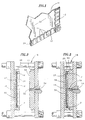
- Figure 2 is a sectional elevation of a mold unit for forming a plastic support layer to be integrated with the deformable layer of material shown in Figure 1, with the mold unit shown in the open position therefor;
- Figure 3 is illustrated similarly to Figure 2 and shows the mold unit in a closed position therefor;
- Figure 4 shows the closed mold unit shown in Figure 3 after a plastic has been injected into the closed mold thus forming a laminate;
- Figure 5 is a sectional side elevation view of the laminate of Figure 4, specifically showing a finished edge; and
- Figure 6 is a bottom plan view of the finished laminate shown in Figure 5.
- In the Figures, a process of forming a laminate 10 (Figs. 5 and 6) is illustrated wherein
edges 12 of adeformable surface layer 14 are folded over and releasably secured (Fig. 1) prior to thedeformable surface layer 14 being placed into amold unit 16 in which a plastic is injected to form asupport layer 18 for thelaminate 10 The process is suitable for materials such as cloth, carpet, film, foil, paper or any other material which is deformable and below which it is desirable to form aplastic support layer 18. It is to be understood that the terms "bottom", "top", "above", "below", "over" and "under" are relative to the laminate as it would be seen in normal use. - In the forming of the
laminate 10, thedeformable surface layer 14 is provided in which theedge portion 12 located along at least a partial perimeter of thedeformable surface layer 14 is folded under (Fig. 1). In order to keep theedge portion 12 of thedeformable surface layer 14 uniformly folded under, along the perimeter of thedeformable surface layer 14, long enough to place thedeformable surface layer 14 into amold unit 16 and to close themold unit 16, a releasable adhesive is placed atintermittent points 20 along the perimeter of thedeformable surface layer 14 between the foldededge portion 12 and anundersurface 22 of thedeformable surface layer 14. The foldededge portion 12 is then pressed against theundersurface 22 of thedeformable surface layer 14 into adhesive contact. It is preferred that the adhesive be of the type which is releasable after time. - In the molding of the
plastic support layer 18 for thelaminate 10, there is provided the plastic injection mold unit 16 (Figs. 2 - 4) having a stationarymale mold portion 24 and a movable female mold portion 25 which, when themold unit 16 is in its closed position (Figs. 3 and 4), form amold cavity 28 for theplastic support layer 18 of thelaminate 10. With themold portions deformable surface layer 14 having itsedge portions 12 folded under and secured to itsundersurface 22, is placed within themold unit 16 and proximate aflat surface 30 of thefemale mold portion 26 When thedeformable surface layer 14 is in place in themold unit 16, theundersurface 22 of thedeformable surface layer 14 is directed towards themale mold portion 24. - The
female mold portion 26 is moved toward themale mold portion 24 and clamped into a closed position (Figs. 3 and 4) wherein a projectingmember 32 of themale mold portion 24 is received within a coactingrecess 34 formed in thefemale mold portion 26 thereby creating themold cavity 28. A plastic material is then injected into themold cavity 28 through a gate opening 36 from aninjection nozzle 38 to fill themold cavity 28 and the space between the foldededge portion 12 of thedeformable surface layer 14 and theundersurface 22 of thedeformable surface layer 14. After themale mold portion 24 and thefemale mold portion 26 have been clamped together, but prior to injection of the elastic material, it is preferred that the adhesive securement between theedge portion 12 of thedeformable surface layer 14 and theundersurface 22 of thedeformable surface layer 14 is released, thus forming a proper or uniform space between theedge portion 12 and theundersurface 22 for the plastic to fill with plastic. Alternatively, if the securement between the foldededge portion 12 and theundersurface 22 of thedeformable surface layer 14 has not released, the injected plastic material enters the tunnel-like space 39 (Fig.1) therebetween and breaks the securement between theedge portion 12 and theundersurface 22 of thedeformable surface layer 14 while concurrently filling the space therebetween. - The
female mold portion 26 is then moved away from themale mold portion 24 and theresultant laminate 10, having adeformable surface layer 14 and aplastic support layer 18 integrated in a total bonded relationship therewith, is removed. - As described hereinabove, the
edge portions 12 of thedeformable surface layer 14 are now uniformly folded under and secured to theedge 40 and thebottom 42 of the plastic support layer 18 (Fig.5) in order to provide a finished edge which provides for improved securement between thedeformable surface layer 14 and theplastic support layer 18 and while giving the laminate 10 a "finished" appearance without tacks or staples. - While an acrylonitrile-butadiene-styrene plastic is preferred as the
plastic support layer 18 of thelaminate 10, other suitable materials may be used such as styrene and polypropylene plastic. Likewise, while a tacky glue is preferred as the releasable adhesive material between theedge portion 12 of thedeformable surface layer 14 and theundersurface 22 of thedeformable surface layer 14, other forms of releasable securement may be used, which either release after a time prior to or upon the injection of the plastic material. - The foregoing description and drawings merely explain and illustrate the invention and the invention is not limited thereto, except insofar as the claims are so limited, as those skilled in the art who have the disclosure before them will be able to make modifications and variations therein without departing from the scope of the invention. By way of example, while a single
deformable surface layer 14 andplastic support layer 18 are shown in thelaminate 10, any number of layers greater than two are also contemplated.
Claims (5)
- A process of injection molding for forming a laminate having a deformable surface layer and a thermoplastic substrate, as the bonding agent, said process comprising the steps of:(a) providing a male mold member and a female mold member;(b) folding under an edge portion along at least a partial perimeter of said deformable surface layer;(c) releasably securing said folded edge portion of said deformable surface layer to the undersurface of said deformable surface layer;(d) placing said deformable surface layer between said male mold member and said female mold member;(e) clamping said male mold member and said female mold member together to form a mold cavity;(f) allowing time for said securement between said folded edge portion and said undersurface of said deformable surface to release;(g) injecting a plastic material into the mold cavity and between said folded perimeter edge portion of said deformable surface layer and said undersurface of said deformable surface layer;(h) allowing said plastic material to at least partially cool and harden; and then(i) removing the resultant laminate from the mold cavity.
- The process, according to Claim 1, further comprising the steps of:(a) placing an adhesive at intermittent points between said perimeter edge portion of said deformable surface layer and said undersurface of said deformable surface layer; and then(b) applying pressure to secure releasably the points of adhesive contact between said folded edge portion of said deformable surface layer and said undersurface of said deformable surface layer.
- A process of injection molding for forming a laminate having a fabric surface layer upon a plastic support layer, said process comprising the steps of:(a) providing a male mold member and a female mold member;(b) folding under an edge portion along at least a partial perimeter of a main portion of said fabric surface layer;(c) releasably attaching said edge portion to an undersurface of said main portion of said fabric surface layer;(d) placing said fabric surface layer between said male mold member and said female mold member;(e) clamping said male mold member and said female mold member together to form a mold cavity;(f) injecting a plastic material into the mold cavity thus breaking the attachment between said edge portion and said main portion of said fabric surface layer while concurrently filling said edge portion with said plastic;(g) allowing said plastic material to at least partially cool and harden; and then(h) removing the resultant laminate from the mold cavity.
- The process, according to Claim 3, further comprising the steps of:(a) placing an adhesive at spaced intervals between said edge portion and said undersurface of said main portion of said fabric surface layer;(b) applying pressure to secure releasably the points of adhesive contact between said edge portion and said undersurface of said main portion thus forming a tunnel between said edge portion and said undersurface of said main portion of said fabric surface layer; and then(c) breaking said points of adhesive contact by injecting said plastic into said tunnel between said edge portion and said undersurface of said main portion of said fabric surface layer.
- The process according to any of the preceding claims, wherein the placing step involves directing the undersurface of the surface layer towards the male mold member.
Applications Claiming Priority (2)
| Application Number | Priority Date | Filing Date | Title |
|---|---|---|---|
| US07/665,571 US5110532A (en) | 1991-03-04 | 1991-03-04 | Method for molding a laminate |
| US665571 | 2000-09-19 |
Publications (2)
| Publication Number | Publication Date |
|---|---|
| EP0502606A2 true EP0502606A2 (en) | 1992-09-09 |
| EP0502606A3 EP0502606A3 (en) | 1993-01-07 |
Family
ID=24670658
Family Applications (1)
| Application Number | Title | Priority Date | Filing Date |
|---|---|---|---|
| EP19920300625 Withdrawn EP0502606A3 (en) | 1991-03-04 | 1992-01-24 | Method for molding a laminate |
Country Status (4)
| Country | Link |
|---|---|
| US (1) | US5110532A (en) |
| EP (1) | EP0502606A3 (en) |
| JP (1) | JPH0661792B2 (en) |
| KR (1) | KR950005712B1 (en) |
Cited By (5)
| Publication number | Priority date | Publication date | Assignee | Title |
|---|---|---|---|---|
| FR2717116A1 (en) * | 1994-03-12 | 1995-09-15 | Otto Deuschle Modell Formenbau | Plastic molded part lined with a sheet, as well as method and device for its manufacture. |
| EP0692358A1 (en) * | 1994-06-24 | 1996-01-17 | Corell Resin Technology B.V. | Method for manufacturing a plastic board and a board obtained with this method |
| EP0698465A1 (en) * | 1994-08-25 | 1996-02-28 | GEBR. HAPPICH GmbH | Construction element such as covering or trim element or the like as well as method for manufacturing such an element |
| NL9401392A (en) * | 1994-08-29 | 1996-04-01 | Corell Resin Technology Bv | Method for fabricating a plastic lamina provided with a covering film, and lamina obtained via said method |
| EP1272341A1 (en) * | 2000-03-30 | 2003-01-08 | Total Innovative Manufacturing, LLC | Molded finished part and method of making same |
Families Citing this family (5)
| Publication number | Priority date | Publication date | Assignee | Title |
|---|---|---|---|---|
| US5335935A (en) * | 1992-08-31 | 1994-08-09 | Plastic Mold Technology Incorporated | Air bag cover/molded article with integral cover layer of leather |
| US5407342A (en) * | 1993-09-13 | 1995-04-18 | Boucher; Paul Y. | Apparatus for manufacturing a composite product |
| US5756406A (en) * | 1994-11-30 | 1998-05-26 | Blue Water Plastics, Inc. | Method of making a soft trim composite, and improved soft trim composite |
| US5853510A (en) * | 1994-12-12 | 1998-12-29 | Blue Water Plastics, Inc. | Method for manufacturing a composite |
| US20070199797A1 (en) * | 2006-02-24 | 2007-08-30 | Dow Global Technologies Inc. | Molded parts with fabric surface areas and processes for their production |
Citations (4)
| Publication number | Priority date | Publication date | Assignee | Title |
|---|---|---|---|---|
| US2684502A (en) * | 1949-09-30 | 1954-07-27 | Paulve Marcel Luc Amedee | Method of making cartridges |
| FR1408790A (en) * | 1964-07-08 | 1965-08-20 | Dynamit Nobel Ag | Process for the application of a plastic cover layer on construction parts, in particular on plates and shaped parts of wood for the manufacture of furniture |
| JPS6141517A (en) * | 1984-08-03 | 1986-02-27 | Toyoda Gosei Co Ltd | Manufacture of molded item with skin |
| JPH01229607A (en) * | 1988-03-11 | 1989-09-13 | Nippon Plast Co Ltd | Mold equipped with device for curling terminal of skin |
Family Cites Families (3)
| Publication number | Priority date | Publication date | Assignee | Title |
|---|---|---|---|---|
| US4206570A (en) * | 1978-04-17 | 1980-06-10 | Cooper William E | Device for supporting a vessel |
| US4499131A (en) * | 1983-03-17 | 1985-02-12 | Albert Shelton | Reusable moisture impervious underpad |
| JPS63302885A (en) * | 1987-06-01 | 1988-12-09 | 日産自動車株式会社 | Integral molded seat |
-
1991
- 1991-03-04 US US07/665,571 patent/US5110532A/en not_active Expired - Fee Related
-
1992
- 1992-01-24 EP EP19920300625 patent/EP0502606A3/en not_active Withdrawn
- 1992-02-27 KR KR1019920003055A patent/KR950005712B1/en not_active IP Right Cessation
- 1992-03-04 JP JP4047171A patent/JPH0661792B2/en not_active Expired - Lifetime
Patent Citations (4)
| Publication number | Priority date | Publication date | Assignee | Title |
|---|---|---|---|---|
| US2684502A (en) * | 1949-09-30 | 1954-07-27 | Paulve Marcel Luc Amedee | Method of making cartridges |
| FR1408790A (en) * | 1964-07-08 | 1965-08-20 | Dynamit Nobel Ag | Process for the application of a plastic cover layer on construction parts, in particular on plates and shaped parts of wood for the manufacture of furniture |
| JPS6141517A (en) * | 1984-08-03 | 1986-02-27 | Toyoda Gosei Co Ltd | Manufacture of molded item with skin |
| JPH01229607A (en) * | 1988-03-11 | 1989-09-13 | Nippon Plast Co Ltd | Mold equipped with device for curling terminal of skin |
Non-Patent Citations (2)
| Title |
|---|
| PATENT ABSTRACTS OF JAPAN vol. 10, no. 196 (M-497)(2252) 10 July 1986 & JP-A-61 041 517 ( TOYODA GOSEI CO LTD ) * |
| PATENT ABSTRACTS OF JAPAN vol. 13, no. 555 (M-904)(3903) 11 December 1989 & JP-A-01 229 607 ( NIPPON PLAST CO LTD ) * |
Cited By (9)
| Publication number | Priority date | Publication date | Assignee | Title |
|---|---|---|---|---|
| FR2717116A1 (en) * | 1994-03-12 | 1995-09-15 | Otto Deuschle Modell Formenbau | Plastic molded part lined with a sheet, as well as method and device for its manufacture. |
| US5928464A (en) * | 1994-03-12 | 1999-07-27 | Otto Deuschle Modell-Und Formenabau Gmbh & Co. | Film laminated plastic moulding as well as process and device for its manufacture |
| US6126769A (en) * | 1994-03-12 | 2000-10-03 | Otto Deuschle Modell-Und Formenbau Gmbh & Co. | Film laminated plastic moulding as well as process and device for its manufacture |
| EP0692358A1 (en) * | 1994-06-24 | 1996-01-17 | Corell Resin Technology B.V. | Method for manufacturing a plastic board and a board obtained with this method |
| US6193916B1 (en) | 1994-06-24 | 2001-02-27 | Corell Resin Technology B.V. | Method for manufacturing a plastic board |
| EP0698465A1 (en) * | 1994-08-25 | 1996-02-28 | GEBR. HAPPICH GmbH | Construction element such as covering or trim element or the like as well as method for manufacturing such an element |
| NL9401392A (en) * | 1994-08-29 | 1996-04-01 | Corell Resin Technology Bv | Method for fabricating a plastic lamina provided with a covering film, and lamina obtained via said method |
| EP1272341A1 (en) * | 2000-03-30 | 2003-01-08 | Total Innovative Manufacturing, LLC | Molded finished part and method of making same |
| EP1272341A4 (en) * | 2000-03-30 | 2003-06-25 | Total Innovative Mfg Llc | Molded finished part and method of making same |
Also Published As
| Publication number | Publication date |
|---|---|
| JPH04320816A (en) | 1992-11-11 |
| JPH0661792B2 (en) | 1994-08-17 |
| EP0502606A3 (en) | 1993-01-07 |
| US5110532A (en) | 1992-05-05 |
| KR950005712B1 (en) | 1995-05-29 |
| KR920017784A (en) | 1992-10-21 |
Similar Documents
| Publication | Publication Date | Title |
|---|---|---|
| US5110532A (en) | Method for molding a laminate | |
| JPH02175111A (en) | Manufacture of synthetic resin molded product coated with skin material and device therefor | |
| JPS61169347A (en) | Interior constituent for automobile | |
| EP0904194B1 (en) | Fabrication of multiple color, gauge, and textured interior auto components | |
| JPH10258699A (en) | Air bag pad and manufacture thereof | |
| US5762852A (en) | Process for making molded-in lamina hinge | |
| EP0576129B1 (en) | Method of seam location using vacuum | |
| US3750938A (en) | Plastic closure for paper containers and metho of making same | |
| JPH0225806B2 (en) | ||
| JP3153038B2 (en) | Manufacturing method of skin adhesive sheet | |
| JPH0582807B2 (en) | ||
| JPS5921306B2 (en) | Pasting method for laminated resin molded products | |
| JPS58168550A (en) | Skin member of sheet for car and its molding method | |
| JPS5849229A (en) | Injection molding method of adhered molded item | |
| JPH1158396A (en) | Manufacture of laminate | |
| JPH0462844B2 (en) | ||
| JP3230047B2 (en) | Manufacturing method of decorative molded products | |
| JPH0378056B2 (en) | ||
| JPS6049101B2 (en) | Manufacturing method of rubber mat with carpet | |
| JPS6463111A (en) | Method for integrally forming composite formed item | |
| JPH02265734A (en) | Manufacture of corrugated fiberboard molding | |
| JPH0534131B2 (en) | ||
| JPS61230920A (en) | Manufacture of skin insert mold product | |
| JPS6250599B2 (en) | ||
| JPH0324891B2 (en) |
Legal Events
| Date | Code | Title | Description |
|---|---|---|---|
| PUAI | Public reference made under article 153(3) epc to a published international application that has entered the european phase |
Free format text: ORIGINAL CODE: 0009012 |
|
| AK | Designated contracting states |
Kind code of ref document: A2 Designated state(s): DE FR IT |
|
| PUAL | Search report despatched |
Free format text: ORIGINAL CODE: 0009013 |
|
| AK | Designated contracting states |
Kind code of ref document: A3 Designated state(s): DE FR IT |
|
| 17P | Request for examination filed |
Effective date: 19930319 |
|
| 17Q | First examination report despatched |
Effective date: 19940829 |
|
| STAA | Information on the status of an ep patent application or granted ep patent |
Free format text: STATUS: THE APPLICATION IS DEEMED TO BE WITHDRAWN |
|
| 18D | Application deemed to be withdrawn |
Effective date: 19950110 |