EP0502413A2 - Einrichtung mit Abtast-Monochromator - Google Patents
Einrichtung mit Abtast-Monochromator Download PDFInfo
- Publication number
- EP0502413A2 EP0502413A2 EP92103285A EP92103285A EP0502413A2 EP 0502413 A2 EP0502413 A2 EP 0502413A2 EP 92103285 A EP92103285 A EP 92103285A EP 92103285 A EP92103285 A EP 92103285A EP 0502413 A2 EP0502413 A2 EP 0502413A2
- Authority
- EP
- European Patent Office
- Prior art keywords
- drive
- housing
- motor
- turntable
- grating
- Prior art date
- Legal status (The legal status is an assumption and is not a legal conclusion. Google has not performed a legal analysis and makes no representation as to the accuracy of the status listed.)
- Withdrawn
Links
Images


Classifications
-
- G—PHYSICS
- G01—MEASURING; TESTING
- G01J—MEASUREMENT OF INTENSITY, VELOCITY, SPECTRAL CONTENT, POLARISATION, PHASE OR PULSE CHARACTERISTICS OF INFRARED, VISIBLE OR ULTRAVIOLET LIGHT; COLORIMETRY; RADIATION PYROMETRY
- G01J3/00—Spectrometry; Spectrophotometry; Monochromators; Measuring colours
- G01J3/02—Details
- G01J3/06—Scanning arrangements arrangements for order-selection
- G01J2003/062—Scanning arrangements arrangements for order-selection motor-driven
- G01J2003/063—Step motor
-
- G—PHYSICS
- G01—MEASURING; TESTING
- G01J—MEASUREMENT OF INTENSITY, VELOCITY, SPECTRAL CONTENT, POLARISATION, PHASE OR PULSE CHARACTERISTICS OF INFRARED, VISIBLE OR ULTRAVIOLET LIGHT; COLORIMETRY; RADIATION PYROMETRY
- G01J3/00—Spectrometry; Spectrophotometry; Monochromators; Measuring colours
- G01J3/02—Details
- G01J3/06—Scanning arrangements arrangements for order-selection
- G01J2003/066—Microprocessor control of functions, e.g. slit, scan, bandwidth during scan
Definitions
- This invention relates to spectral measuring devices, and in particular to devices of the scanning monochromator type.
- a scanning monochromator consists of an entrance aperture, a rotatable dispersing optical element, which is typically a diffracting grating but sometimes a prism, a drive mechanism for rotating the dispersing optical element, an exit aperture, and any additional optical elements which collimate or focus radiation that enters via the entrance aperture.
- Radiation entering the monochromator through the entrance aperture and dispersed by the diffraction grating is imaged at the exit aperture as a narrow wavelength band of radiation. The bandwidth of this radiation depends upon groove density of the diffraction grating, the focal length of the optical system, the width of the entrance and exit apertures, and the incident and diffracted angles off the diffraction grating.
- the dispersed light which exits the monochromator system follows the well-known grating relationship, discussed at pp. 16-17 of "Diffraction Grating Handbook", Bausch & Lomb, Incorporated, Rochester, New York (1970).
- the diffraction grating has been mounted on a platform and rotated by a drive motor through a mechanical drive assembly that includes a sine bar and lead screw.
- the sine-bar drive mechanism has the advantage of producing a linear change in wavelength at the exit aperture of the monochromator, with respect to the lead screw which drives the sine bar, due to the sinusoidal relationship between grating rotation and dispersion. This has facilitated the use of a linear, mechanical counter attached to the shaft of the lead screw, for display of the wavelength of radiation exiting the exit aperture.
- the lead screw is subject to dust or dirt contamination which can dramatically affect accuracy and performance of the drive system.
- the lead screw must be lubricated with oil, requiring frequent oiling maintenance to insure proper lubrication.
- the sine bar rides on a carriage attached to the lead screw; this typically employs a ball and a flat which rub against each other. This is a source of mechanical wear and, if wear is severe enough, the wear is a source of inaccuracy and imprecision of wavelength registration.
- the accuracy and precision of the drive system can be improved by increasing the length of the sine bar and lead screw, the longer and more costly these devices become, and the more time it takes to rotate the diffraction grating through a given angle. Additionally, the speed at which the lead screw can be rotated is limited by the speed at which oil is literally slung off the lead screw.
- the wavelength can be calculated or derived from a "look-up" table if the drive mechanism does not have a sinusoidal response, as does the sine bar/lead-screw mechanism. This circumstance has facilitated use of drive mechanisms that directly rotate the dispersing element of the monochromator. Examples of direct-drive mechanisms are the galvanometer drive, as in Bernier et al. U.S. Patent 4,469,441, and the worm-gear drive.
- the galvanometer-drive system utilizes a galvanometer, coupled directly to the diffraction grating, to rotate the dispersing element.
- the drive is simple and fast, yet it can suffer from hysteresis when it stops at a particular position, and it must utilize a very high resolution input signal (usually a digital-to-analog converter of 16 or more bits, i.e., 216 or more) to control the current to the galvanometer, since current to the galvanometer is related to grating rotation. More importantly, however, the drive has a limited usable range of angular rotation, thereby limiting the wavelength coverage of the monochromator.
- the galvanometer produces enough heat to change its resistance (impedance), and the change in impedance changes the amount of current needed to rotate the drive.
- the temperature changes, so does the calibration of the drive, in that the needed current per degree of rotation is changing, and it is difficult to reproduce a wavelength (at the exit aperture) or angular position (of the dispersing element) with any precision or accuracy.
- the diffraction grating is mounted to a rotatable platform, motor-driven via a worm-gear transmission.
- the worm-gear transmission is susceptible to gear wear as a function of time, leading to poor accuracy and precision, and ultimately requiring replacement of the transmission.
- a specific aspect of the invention is to meet the above object with a drive system for the dispersing element of a monochromator wherein the drive system avoids wear amd inaccuracy problems of prior constructions.
- Another aspect is to provide a dispersing-element drive of such fine resolution and reproducible accuracy as to avoid the need for position-sensed feedback in the control of any specific angular displacement of the dispersing element.
- a general aspect is to meet the above objects with a system of relative simplicity, fast and precise angle-positioning, inherently broad wavelength range, and relative freedom from temperature response or mechanical hysteresis.
- the invention in a preferred embodiment provides a scanning monochromator wherein a pulse-driven micro-stepping motor requiring a very large number of steps per output revolution is directly coupled to the input hub of a reduction-gear harmonic drive having a substantial gear-reduction ratio, and the output hub of the harmonic drive is directly coupled to rotate the dispersing element of the instrument.
- the product of these two reductions namely, steps per motor revolution, times the harmonic gear reduction, results in an illustrative resolution of 5,000,000 pulsed steps per revolution of the dispersing element; and this translates into more than 600,000 incremental angular-displacement steps over a usable 45° range of diffraction-grating rotation.
- the torque-transmitting capabilities and backlash-free nature of the harmonic drive coupled with the essentially no-load condition imposed by direct mounting of the dispersing element, assure precisely repeatable angular settings (i.e. exit-aperture wavelength selection) and trouble-free operation, over a very greatly extended life of the instrument.
- the monochromator instrument of Figs. 1 and 2 is largely contained within a sealed horizontally elongate prismatic system housing 10 of rectangular section, shock-mounted at 11,12, at its respective longitudinal ends.
- An entrance/exit assembly A of means to illuminate and position specimen materials for analysis is removably sealed to housing 10 at one longitudinal end.
- a first cover plate 13 is removably sealed by means 14 to the rim of a first opening near one end of the upper panel 15 of the housing, providing installation and adjustment access to a rotatable diffraction-grating assembly B.
- a second cover plate 16 is removably sealed by means 17 to the rim of a second opening near the other end of panel 15, providing installation and adjustment access to mirror assemblies C, D, on the respective lateral sides of a centrally located vertical plane of housing symmetry which extends the length of the housing and which includes the vertical axis 18 of rotation of the grating assembly B.
- a motor 20 and reduction-gear transmission 21 are unitized to include an adapter or mounting plate 22 having removably sealed assembly to the rim of a downwardly open motor-mounting formation in the lower-panel portion 23 of housing 10.
- the diffraction-grating assembly B is mounted to the output hub or flange of the transmission 21.
- the vertical axis 18 of grating-assembly rotation is also the central axis of motor 20 and transmission 21.
- the assembly A has a port for admission of light on an illuminating axis 24 to an aperture or slit assembly 25, at a window 26 in sealed relation to an entrance port and shielding tube 27 carried at the adjacent end wall of the housing.
- This sealed closure at 26, and the sealed closures at 13, 16 and 22, as well as a drive-shaft seal schematically indicated at 28, complete the envelope integrity of housing 10, whereby an evacuating-pump connection at 29 can, if desired, establish a vacuum environment for all optical components and ray paths involved in scanning monochromator operation.
- the optical ray path will be recognized as conforming to the Czerny-Turner configuration of a plane-grating monochromator.
- light entering the entrance aperture on axis 24 passes the length of housing 10 to a first collimating mirror 30 with suitably adjustable means 31 of support to assure focus on the entrance aperture and to direct the central axis 32 of its collimated ray bundle to the center of the diffraction-grating 33, it being noted that the vertical centerline of the diffraction grating 33 will have been adjusted to coincide with the vertical axis 18 of motor (20) and harmonic-drive (21) rotation.
- the second or focusing mirror 34 is a duplicate of mirror 30 with suitably adjustable means 35 of support to assure focus at the exit aperture on axis 36 while the central axis 37 of its bundle of collimated-ray response coincides with the diffraction-grating center of entrance-ray (32) incidence.
- the exit axis 36 passes through a tubular shield 38 to and through an exit aperture (not shown) but analogous to the slit assembly and sealed window described at 25/26 for the case of the entrance axis 24.
- Monochromatic radiation passing the exit slit is monitored by suitable means contained within the housing of the entrance/exit assembly A.
- monitoring means includes a solar-blind photomultiplier 39, for "straight-shot” exposure to ultraviolet light on the alignment of the exit axis 36, and a visible-light photomultiplier 40 with selectively operable means (not shown) for folding the exit axis 36 away from the straight-shot alignment to a folded alignment for monitoring visible light at 40, to the exclusion of ultraviolet radiation at 39.
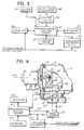
- the diffraction grating 33 is seen to include a mounting stem 41 which is inserted horizontally into a clamp 42 at the upper end of a bracket 43 which, in turn, is mounted to a circular turntable 44 that will be understood to be coupled to the output hub of the harmonic-drive 21; stem 41 is slitted to permit set-screw (45) adjustment of slight up/down flexing of grating 33 about the slit-weakened portion of stem 41.
- the turntable 44 presents an axially short cylindrical periphery for drag-torque engagement to the friction-pad end of a brake-arm assembly 46 which, as seen in Fig.
- the means 47 includes means 47 for adjustably selecting a minimum of drag torque in order to assure a low level of friction action in approach to and retention of a predetermined angular setting of grating 33 about its axis 18 of rotation.
- the means 47 includes a captive softly compliant spring (not shown) to enable careful and precise adjustment of a desired low level of brake-friction development in application to the turntable 44.
- an arm 49 is shown fixed to and depending from turntable 44, at a location of maximum practical radial offset from axis 18.
- Arm 49 carries a small permanent-magnet element 50, and a magnetic detector, preferably a Hall-effect transducer 51 is shown mounted to the end wall of housing 10, poised for identifying electrical response to proximity to the field of magnet 50, when grating 33 is in the approximate position of essentially only reflecting the collimated ray bundle on axis 32 into the collimated response ray bundle on axis 36.
- the Hall-effect transducer is effectively an electric switch, used to locate a defined starting position if the drive ever becomes "lost". For example, if the power is off and the rotary location of the drive mechanism is not known, the drive is rotated until the sensor 51 picks up the magnet. This position, which will be understood to have been previously defined and digitally stored in computer means 56 (Fig. 3) associated with control of the pulse drive of motor 20, now provides a starting point from which drive rotation can be calibrated. Without this "switch" at 51, it would be difficult (but not impossible) to locate the starting position for grating rotation.
- the gear-reducing harmonic drive 21 may be a commercial product , Model PCR 5C-200-1, available from Harmonic Drive Corporation of Wakefield, Massachusetts, operating directly from the output shaft of a microstepping motor 20.
- the harmonic drive may be as described in U.S. Patent 2,906,143, and the indicated model has a 200:1 gear-reduction ratio. Further effective reduction (i.e. fineness of driven-angle resolution) is achieved by selection of a motor 20 that requires a large number of pulse-responsive steps for a single rotation of the motor-output shaft. In the presently preferred embodiment, motor 20 requires 25,000 successive electrical input pulses, to achieve as many incremental-angle steps, for one rotation of its shaft.
- the grating 33 has a 45° range of angular displacement, with respect to the "zero" or solely reflecting aspect of grating 33. This being the case, 625,000 stepping pulses to motor 20 are needed to run grating 33 through its 45° range of displaceability.
- the indicated commercial motor 20 and harmonic drive 21 were subjected to slight modification: (1) to accommodate the adaptor or mounting plate 22, (2) to incorporate vacuum-seal means 28 at motor 21 connection to the harmonic drive 21, and (3) to eliminate elastomeric-seal means which is customarily supplied for the output hub of the harmonic drive.
- the latter measure will be understood to avoid any residual torsional stress operative at the output of the harmonic drive because the number of steps per rotation means an incredibly small incremental angle grating advance per step, amounting to 7x10 ⁇ 5 degrees per step, i.e. 0.25 arc-sec/step.
- Residual torsional stress of an elastomeric output-hub seal might relieve itself in the equivalent amount of several of such finely divided steps, upon achieving a driven grating-displacement angle; to retain such a seal in the described monochromator would therefore be a source of positioning errors and ambiguity, effectively jettisoning the precision and resolution which flow from the indicated 10 ⁇ 5 order of magnitude of angular accuracy inherent in the described system.
- a low level of torsional friction devoid of torsionally stressed compliant deformation, is selectively available through the described brake-arm adjustment at 47, to retain precisely indexed displacements of grating 33.
- Fig. 3 is a simplified diagram that is suggestive and schematically indicative of control for the described stepping-motor 20 drive of the gear reducing harmonic drive 21 .
- control means 55 in conjunction with a computer 56 is programmable and/or "manually" operable pursuant to digital inputs from keyboard means 57.
- Basic pulse input to control means 55 derives motor-stepping pulses from a clock-pulse generator 58, in conjunction with counter means 59 having provision for selection of different divided pulse-rate outputs to the control means 55; such selectivity is parenthetically suggested by alternate factors a, b by which the clock-pulse rate can be divided, so as to provide selection of "fast” or “slow” stepping speeds of motor 20.
- control connection from means 55 to counter 59 will be understood to govern the functions of (i) determining whether to divide by a or by b, (ii) to determine the number of stepping pulses to be supplied to motor 20, and (iii) to determine the direction of the count (i.e. count up, or count down) whereby to determine the direction of motor 20 rotation.
- An indicator/recorder 60 is shown connected to monitor the controlled stepping-pulse output to motor 20, whereby to provide an instantaneous indication and/or recording of diffraction-grating angle or wavelength, for incremental wavelength scanning readable at one or the other of photomultipliers 39, 40, and a second input 61 to the indicator/recorder 60 is schematically shown to supply instantaneous photomultiplier response amplitude, enabling two-dimensional indication, display or recording at 60, for observed exit-aperture amplitude as a function of grating-angle ⁇ (or wavelength ) departure from the "zero" (or maximum reflection) location.
- the output of Hall-effect transducer 51 is shown as having an additional input connection to the control means 55.
- Fig. 4 schematically shows that the invention is not necessarily limited to the stepping-pulse drive available with motor 20 of Figs. 1 and 2, although, as indicated above, the embodiment of Figs. 1 and 2 is definitely preferred for reasons given above, not the least of which is the great number of discrete angles that can be called for at motor 20, without need for feedback control.
- Fig. 4 schematically shows that the invention is not necessarily limited to the stepping-pulse drive available with motor 20 of Figs. 1 and 2, although, as indicated above, the embodiment of Figs. 1 and 2 is definitely preferred for reasons given above, not the least of which is the great number of discrete angles that can be called for at motor 20, without need for feedback control.
- Fig. 4 schematically shows that the invention is not necessarily limited to the stepping-pulse drive available with motor 20 of Figs. 1 and 2, although, as indicated above, the embodiment of Figs. 1 and 2 is definitely preferred for reasons given above, not the least of which is the great number of discrete angles that can be called for at
- motor 20' is illustratively, a so-called stalled-torque motor wherein a separate motor winding is provided for each direction of motor (20') rotation and wherein current is provided at all times to both windings, to produce zero speed when the windings produce equal and opposite torque, but to drive in one or the other direction in accordance with the sign of instantaneous torque unbalance.
- motor 20' is illustratively, a so-called stalled-torque motor wherein a separate motor winding is provided for each direction of motor (20') rotation and wherein current is provided at all times to both windings, to produce zero speed when the windings produce equal and opposite torque, but to drive in one or the other direction in accordance with the sign of instantaneous torque unbalance.
- the line connection 62 from control means 55' to motor 20' will be understood to govern the drive motor in such stalled-torque operation, in accordance with the extent to which a programmed angle setting (evaluated against instantaneous motor-shaft angle encoding at 63) indicates that further drive torque in a given direction is still needed, for achievement of the programmed angle.
- a programmed angle setting evaluation against instantaneous motor-shaft angle encoding at 63
- the use of motor 20' to directly drive the harmonic-drive reduction gear 21 provides greatly enhanced and finely divided resolution of grating-angle positioning; but such resolution requires a great number of binary digit elements, e.g. 15, for a 215 subdivision of one revolution of motor 20'.
Landscapes
- Physics & Mathematics (AREA)
- Spectroscopy & Molecular Physics (AREA)
- General Physics & Mathematics (AREA)
- Spectrometry And Color Measurement (AREA)
- Investigating Or Analysing Materials By Optical Means (AREA)
Applications Claiming Priority (2)
| Application Number | Priority Date | Filing Date | Title |
|---|---|---|---|
| US07/664,592 US5096295A (en) | 1991-03-01 | 1991-03-01 | Scanning monochromator |
| US664592 | 1991-03-01 |
Publications (2)
| Publication Number | Publication Date |
|---|---|
| EP0502413A2 true EP0502413A2 (de) | 1992-09-09 |
| EP0502413A3 EP0502413A3 (en) | 1993-02-10 |
Family
ID=24666614
Family Applications (1)
| Application Number | Title | Priority Date | Filing Date |
|---|---|---|---|
| EP19920103285 Withdrawn EP0502413A3 (en) | 1991-03-01 | 1992-02-26 | Scanning monochromator system |
Country Status (3)
| Country | Link |
|---|---|
| US (1) | US5096295A (de) |
| EP (1) | EP0502413A3 (de) |
| JP (1) | JPH0572034A (de) |
Cited By (1)
| Publication number | Priority date | Publication date | Assignee | Title |
|---|---|---|---|---|
| EP1442697A1 (de) * | 2003-01-29 | 2004-08-04 | Nidek Co., Ltd | Optometrisches Instrument |
Families Citing this family (12)
| Publication number | Priority date | Publication date | Assignee | Title |
|---|---|---|---|---|
| US5625270A (en) * | 1996-02-29 | 1997-04-29 | Hach Company | Scanning monochromator with directly driven spectral-dispersion element |
| JPH10164327A (ja) * | 1996-11-29 | 1998-06-19 | Olympus Optical Co Ltd | 画像入力装置 |
| US6587199B1 (en) * | 2000-02-25 | 2003-07-01 | Sensys Medical, Inc. | Embedded data acquisition and control system for non-invasive glucose prediction instrument |
| JP3952931B2 (ja) * | 2002-11-11 | 2007-08-01 | 株式会社島津製作所 | 分光光度計 |
| JP2006106209A (ja) * | 2004-10-01 | 2006-04-20 | Canon Inc | 駆動機構制御装置、画像形成装置、駆動機構制御方法、及びプログラム |
| US9404799B2 (en) * | 2013-03-15 | 2016-08-02 | Westco Scientific Instruments, Inc. | Tandem dispersive range monochromator |
| US9395245B2 (en) * | 2013-03-15 | 2016-07-19 | Westco Scientific Instruments, Inc. | Data knitting tandem dispersive range monochromator |
| US10523081B2 (en) | 2014-11-25 | 2019-12-31 | Black & Decker Inc. | Brushless motor for a power tool |
| US10786894B2 (en) | 2015-10-14 | 2020-09-29 | Black & Decker Inc. | Brushless motor system for power tools |
| US10215635B2 (en) | 2017-01-26 | 2019-02-26 | Westco Scientific Instruments, Inc | Data blending multiple dispersive range monochromator |
| WO2025114244A1 (en) | 2023-11-27 | 2025-06-05 | Witec Wissenschaftliche Instrumente Und Technologie Gmbh | Rotary adjustment stage for a setup, in particular with an optical element |
| DE102023132964A1 (de) * | 2023-11-27 | 2025-05-28 | Witec Wissenschaftliche Instrumente Und Technologie Gmbh | Drehversteller für einen Aufbau, insbesondere mit einem Optikelement |
Family Cites Families (5)
| Publication number | Priority date | Publication date | Assignee | Title |
|---|---|---|---|---|
| US4211486A (en) * | 1978-03-20 | 1980-07-08 | Altex Scientific, Inc. | Spectrophotometer |
| US4469441A (en) * | 1982-03-04 | 1984-09-04 | Allied Corporation | Scanning monochromator system with direct coupled dispersing element-electromagnetic drive transducer assembly |
| US4514819A (en) * | 1982-06-04 | 1985-04-30 | Harris Graphics Corporation | Apparatus and method for measuring rotational position |
| DE3231553A1 (de) * | 1982-08-25 | 1984-03-01 | Liebherr-Aero-Technik Gmbh, 8998 Lindenberg | Elektromechanischer stellantrieb |
| US4540282A (en) * | 1983-03-21 | 1985-09-10 | Isaac Landa | Apparatus for optically analyzing a sample |
-
1991
- 1991-03-01 US US07/664,592 patent/US5096295A/en not_active Expired - Fee Related
-
1992
- 1992-02-26 EP EP19920103285 patent/EP0502413A3/en not_active Withdrawn
- 1992-02-28 JP JP4044021A patent/JPH0572034A/ja not_active Withdrawn
Cited By (2)
| Publication number | Priority date | Publication date | Assignee | Title |
|---|---|---|---|---|
| EP1442697A1 (de) * | 2003-01-29 | 2004-08-04 | Nidek Co., Ltd | Optometrisches Instrument |
| US7144112B2 (en) | 2003-01-29 | 2006-12-05 | Nidek Co., Ltd. | Optometric apparatus |
Also Published As
| Publication number | Publication date |
|---|---|
| EP0502413A3 (en) | 1993-02-10 |
| US5096295A (en) | 1992-03-17 |
| JPH0572034A (ja) | 1993-03-23 |
Similar Documents
| Publication | Publication Date | Title |
|---|---|---|
| US5096295A (en) | Scanning monochromator | |
| US7796252B2 (en) | Scanning monochromator with direct drive grating | |
| US4697924A (en) | Monochromator | |
| CN108152313B (zh) | X射线荧光光谱仪的分光光路自动调试与校正系统及方法 | |
| US3743427A (en) | Modulation transfer function measurement system and method | |
| JP2609616B2 (ja) | フォトメータおよび光測定方法 | |
| CA1236704A (en) | Grating ozone spectrophotometer | |
| US4364122A (en) | X-Ray diffraction method and apparatus | |
| JP5873775B2 (ja) | 回折格子ホルダ、回折格子評価装置、および測定装置 | |
| Burnet et al. | A computerized differential photometer for the Geneva Seven Colour Photometric System | |
| JPS6315793Y2 (de) | ||
| JPH05196586A (ja) | X線解析装置 | |
| US4971439A (en) | Wavelength calibration method and apparatus | |
| WO2004059269A1 (en) | Variable exposure rotary spectrometer | |
| Parrish et al. | Geometry, alignment and angular calibration of X-ray diffractometers | |
| GB2136591A (en) | Sine bar mechanism and monochromator and spectrophotometer including such a sine bar mechanism | |
| JPS626127A (ja) | 分光光度計 | |
| DE3904122C2 (de) | ||
| EP0096317B1 (de) | Gittermonochromator | |
| US4838691A (en) | Method and apparatus for determining calibration accuracy of a scientific instrument | |
| JPS59153153A (ja) | X線分析装置 | |
| Davis et al. | On choosing off-line automatic X-ray diffractometers | |
| Hindle et al. | A control system for a fully automatic pressure scanned Fabry-Pérot interferometer | |
| CN223449339U (zh) | 一种立式分布式光度计 | |
| JP2000009533A (ja) | 分光器 |
Legal Events
| Date | Code | Title | Description |
|---|---|---|---|
| PUAI | Public reference made under article 153(3) epc to a published international application that has entered the european phase |
Free format text: ORIGINAL CODE: 0009012 |
|
| AK | Designated contracting states |
Kind code of ref document: A2 Designated state(s): AT BE CH DE DK ES FR GB GR IT LI LU MC NL PT SE |
|
| PUAL | Search report despatched |
Free format text: ORIGINAL CODE: 0009013 |
|
| AK | Designated contracting states |
Kind code of ref document: A3 Designated state(s): AT BE CH DE DK ES FR GB GR IT LI LU MC NL PT SE |
|
| STAA | Information on the status of an ep patent application or granted ep patent |
Free format text: STATUS: THE APPLICATION IS DEEMED TO BE WITHDRAWN |
|
| 18D | Application deemed to be withdrawn |
Effective date: 19930811 |