EP0502199B1 - Ultraschallmikroskop - Google Patents
Ultraschallmikroskop Download PDFInfo
- Publication number
- EP0502199B1 EP0502199B1 EP91915620A EP91915620A EP0502199B1 EP 0502199 B1 EP0502199 B1 EP 0502199B1 EP 91915620 A EP91915620 A EP 91915620A EP 91915620 A EP91915620 A EP 91915620A EP 0502199 B1 EP0502199 B1 EP 0502199B1
- Authority
- EP
- European Patent Office
- Prior art keywords
- sample
- acoustic lens
- attenuator
- signal
- ultrasonic
- Prior art date
- Legal status (The legal status is an assumption and is not a legal conclusion. Google has not performed a legal analysis and makes no representation as to the accuracy of the status listed.)
- Expired - Lifetime
Links
- 238000005259 measurement Methods 0.000 description 6
- 238000000034 method Methods 0.000 description 5
- 238000013459 approach Methods 0.000 description 3
- 230000005540 biological transmission Effects 0.000 description 3
- 230000004044 response Effects 0.000 description 3
- 229920006395 saturated elastomer Polymers 0.000 description 3
- 238000010586 diagram Methods 0.000 description 2
- 230000002708 enhancing effect Effects 0.000 description 2
- 230000002238 attenuated effect Effects 0.000 description 1
- 230000000593 degrading effect Effects 0.000 description 1
- 239000006185 dispersion Substances 0.000 description 1
- 239000007788 liquid Substances 0.000 description 1
- 239000000463 material Substances 0.000 description 1
- 238000000926 separation method Methods 0.000 description 1
Images

Classifications
-
- G—PHYSICS
- G01—MEASURING; TESTING
- G01S—RADIO DIRECTION-FINDING; RADIO NAVIGATION; DETERMINING DISTANCE OR VELOCITY BY USE OF RADIO WAVES; LOCATING OR PRESENCE-DETECTING BY USE OF THE REFLECTION OR RERADIATION OF RADIO WAVES; ANALOGOUS ARRANGEMENTS USING OTHER WAVES
- G01S7/00—Details of systems according to groups G01S13/00, G01S15/00, G01S17/00
- G01S7/52—Details of systems according to groups G01S13/00, G01S15/00, G01S17/00 of systems according to group G01S15/00
- G01S7/52017—Details of systems according to groups G01S13/00, G01S15/00, G01S17/00 of systems according to group G01S15/00 particularly adapted to short-range imaging
- G01S7/52023—Details of receivers
- G01S7/52033—Gain control of receivers
-
- G—PHYSICS
- G01—MEASURING; TESTING
- G01N—INVESTIGATING OR ANALYSING MATERIALS BY DETERMINING THEIR CHEMICAL OR PHYSICAL PROPERTIES
- G01N29/00—Investigating or analysing materials by the use of ultrasonic, sonic or infrasonic waves; Visualisation of the interior of objects by transmitting ultrasonic or sonic waves through the object
- G01N29/04—Analysing solids
- G01N29/06—Visualisation of the interior, e.g. acoustic microscopy
-
- G—PHYSICS
- G01—MEASURING; TESTING
- G01N—INVESTIGATING OR ANALYSING MATERIALS BY DETERMINING THEIR CHEMICAL OR PHYSICAL PROPERTIES
- G01N29/00—Investigating or analysing materials by the use of ultrasonic, sonic or infrasonic waves; Visualisation of the interior of objects by transmitting ultrasonic or sonic waves through the object
- G01N29/22—Details, e.g. general constructional or apparatus details
-
- G—PHYSICS
- G01—MEASURING; TESTING
- G01S—RADIO DIRECTION-FINDING; RADIO NAVIGATION; DETERMINING DISTANCE OR VELOCITY BY USE OF RADIO WAVES; LOCATING OR PRESENCE-DETECTING BY USE OF THE REFLECTION OR RERADIATION OF RADIO WAVES; ANALOGOUS ARRANGEMENTS USING OTHER WAVES
- G01S15/00—Systems using the reflection or reradiation of acoustic waves, e.g. sonar systems
- G01S15/88—Sonar systems specially adapted for specific applications
- G01S15/89—Sonar systems specially adapted for specific applications for mapping or imaging
- G01S15/8906—Short-range imaging systems; Acoustic microscope systems using pulse-echo techniques
- G01S15/8909—Short-range imaging systems; Acoustic microscope systems using pulse-echo techniques using a static transducer configuration
- G01S15/8911—Short-range imaging systems; Acoustic microscope systems using pulse-echo techniques using a static transducer configuration using a single transducer for transmission and reception
-
- G—PHYSICS
- G10—MUSICAL INSTRUMENTS; ACOUSTICS
- G10K—SOUND-PRODUCING DEVICES; METHODS OR DEVICES FOR PROTECTING AGAINST, OR FOR DAMPING, NOISE OR OTHER ACOUSTIC WAVES IN GENERAL; ACOUSTICS NOT OTHERWISE PROVIDED FOR
- G10K11/00—Methods or devices for transmitting, conducting or directing sound in general; Methods or devices for protecting against, or for damping, noise or other acoustic waves in general
- G10K11/18—Methods or devices for transmitting, conducting or directing sound
- G10K11/26—Sound-focusing or directing, e.g. scanning
- G10K11/30—Sound-focusing or directing, e.g. scanning using refraction, e.g. acoustic lenses
Definitions
- the present invention relates to an ultrasonic microscope for viewing the surface and inside of a sample using ultrasonic pulses.
- an acoustic lens is used.
- An ultrasonic wave is focused into a micro-spot and directed to a sample through the acoustic lens.
- a reflected wave from the sample is received and converted into received electric signal.
- a part of this received signal is gated to pick up a portion of the simple-reflected wave.
- the peak value of the reflected wave component thus picked up is detected to obtain a piece of information relating to a point on the sample.
- the peak value or strength of the detected value becomes the largest when the acoustic lens is focused on the sample.
- Some automatic focusing methods of the acoustic lens which use this fact have been proposed.
- the timing at which the reflected waves from the sample surface are received at the time the acoustic lens is focused can be calculated as a delay from the reference time such as the signal transmitting time.
- the gating is carried out at this timing, therefore, the reflected wave from the sample can be picked up and its strength can be measured.
- the strength of the reflected wave from the sample is compared with a threshold value while moving the acoustic lens from a position remote enough from the sample to the sample. When these two values coincide with each other or the value measured exceeds the threshold value, the acoustic lens is stopped.
- the automatic focusing of the acoustic lens can be achieved in this manner.
- the threshold value is made a little smaller than the strength of the reflected wave at the focus point.
- the threshold value is compared with peak values in the two gates.
- the automatic focusing of the acoustic lens can also be achieved in this manner. More specifically, the first gate is set at the time when the wave reflected from the sample surface at the focus point is received, and the second gate is set near this time. There are then used a circuit for checking that the strength of the detected signal of that reflected wave picked up by the first gate becomes larger than that picked up by the second gate, a circuit for checking that the strength of the detected signal at the first gate exceeds the threshold value, and an AND circuit for outputs of both circuits.
- the acoustic lens can be stopped responsive to output applied from the AND circuit.
- an ultrasonic microscope system for measuring the acoustic characteristics of a sample.
- the microscope system described belongs to the class of acoustic velocity measuring apparatus recording the acoustic characteristic curve (the V(z)-curve), the periodicity of which is indicative of the acoustic properties of the material under examination. Accordingly, in this class of ultrasonic microscope systems, the dip interval representing the periodicity of the V(z)-curve is measured allowing the determination of the above mentioned acoustic characteristics.
- the object to be solved by the apparatus in accordance with this prior art approach is to provide an ultrasonic microscope which permits accurate measurements of the dip intervals even if the dip intervals and the shape of the V(z)-curve have irregularities. Accordingly, a wave reflected from the sample is received and the V(z)-curve of variations in the level of the reflective wave with respect to a relative movement between the ultrasonic lens and the sample is measured. A reference level of interference of a directly reflected wave and a leakly elastic wave is substracted from V(z) to perform waveform processing the output of which is subjected to a waveform analysis allowing the determination of the velocity and/or attenuation of the leakly elastic wave.
- the threshold values are set to a level near the strength of the reflected wave obtained at the same time when the acoustic lens is focused on the sample.
- the threshold value must be adjusted to an appropriate level every time the reflective sample is replaced by a new one since the strength of the reflected wave depends on the respective sample under examination.
- an ultrasonic microscope is provided enabling the operator to more easily achieve automatic focusing but making it unnecessary for the operator to adjust the threshold value every time the sample is replaced by a new one.
- the object of the present invention can be attained by an ultrasonic microscope wherein ultrasonic waves converged by an acoustic lens are made incident onto a sample. Reflected waves from the sample are received and converted into received electric signals, and the ultrasonic wave image of the sample is formed using the received signals, said ultrasonic microscope comprising a means for adjusting the distance of the acoustic lens relative to the sample; a means for picking up those of the received electric signals which correspond to a part of the reflected signals from the sample; a converter means for gain-adjusting an output signal applied from the pickup means; a means for comparing the strength of the signal gain-adjusted by the converter means with a previously-set threshold value; a gain control means for adjusting the gain of said converter means on the basis of comparison values obtained by said converter means so as to bring the signal input/output rate of said converter means to an optional value; and a focus adjustment control means for calculating the focus position of said acoustic lens on the basis of a gain-changing curve obtained
- the ultrasonic microscope of the present invention a part of that electric signal which corresponds to the reflected wave from the sample is picked up by the pickup means and applied to the converter means.
- the strength of the signal gain-adjusted by the converter means is compared with the threshold value by the comparator means.
- the gain of the converter means is adjusted on the basis of the result obtained by this comparison so as to bring its input/output rate to a desired value.
- the focused position of the acoustic lens is calculated by the focus adjustment control means from a gain curve of the converter means which changes when the acoustic lens is moved from a position, remote enough from its focused position, to the sample.
- a rive signal which corresponds to the result thus calculated is applied to the distance adjuster means. As the result, the distance of the acoustic lens relative to the sample can be adjusted to make the acoustic lens focused on the sample.
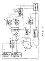
- Fig. 1 is a block diagram showing the ultrasonic microscope provided with an automatic focusing system according to an embodiment of the present invention.
- An ultrasonic pulse transmitting and receiving means comprises a pulse transmitter section 1, a transducer 2 for converting the pulse received from the pulse transmitter section 1 into an ultrasonic pulse, and an acoustic lens 3 for focusing the ultrasonic pulse created by the transducer 2 onto a sample 5 as a micro-spot.
- a sample 5 is placed in a sample container 4, and a coupler liquid 6 is provided for transmitting the ultrasonic pulse between the acoustic lens 3 and the sample 5 in the sample container 4.
- the ultrasonic pulse incident on the sample 5 is reflected by the top, bottom or inside of the sample 5.
- a gate section 8 is connected to the output side of the pre-amplifier 7.
- the gate section 8 serves to gate the received electric signal at such a timing that an output component which corresponds to the focus position of the acoustic lens 3 can be picked up from the signal.
- An attenuator 9 is connected to the gate section 8. The attenuation of this attenuator 9 is adjusted, as will be described later, to keep the ratio of its input and output at a predetermined value.
- the output of the attenuator 9 is detected by a peak detector section 10.
- the output of the peak detector section 10 is applied to an input terminal of comparator 11 and also to an A/D converter section 12.
- a threshold value is applied from a threshold value level setting section 13 to another input terminal of the comparator 11.
- the comparator 11 produces an "ON" output only when the output or detected value of the peak detector section 10 exceeds the threshold value.
- Outputs of the comparator 11 and the A/D converter section 12 are applied to a computer 14.
- the acoustic lens 3 is moved in a direction in which the ultrasonic pulse enters into the acoustic lens 3, or in a direction Z, by a Z drive section 15.
- a Z-drive controller section 16 When a Z-drive controller section 16 receives a command signal from the computer 14, it applies a drive signal to the Z-drive section 15, which is made operative in response to this applied drive signal. Further, when an XY-scanner section 17 receives an XY scanning signal from the computer 14, the sample 5 is scanned in directions X and Y by the XY scanner section 17.
- a pulse controller section 18 outputs a transmission trigger signal to the pulse transmitter section 1 in response to a transmission timing signal applied from the computer 14.
- a gate width adjuster section 19 is connected to the output of the pulse controller section 18 and the output of the computer 14 to adjust the gate width of the gate section 8 in response to a command applied from the computer 14.
- the pulse transmitter section 1 When the transmission trigger signal is applied from the pulse controller section 18 to the pulse transmitter section 1, the pulse transmitter section 1 generates a single pulse signal, which is electro-acoustically converted into an ultrasonic pulse by the transducer 2. This ultrasonic pulse enters into the sample 5, passing through the acoustic lens 3. The reflected wave from the sample 5 is again passed through the acoustic lens 3 and converted into an electric (or received) signal by the transducer 2.
- the pulse controller section 18 outputs a pulse to the gate width adjuster section 19 at such a timing that can be calculated from the working distance inherent to the acoustic lens 3.
- the gate width adjuster section 19 outputs such a gate signal to the gate section 8 that has a time width large enough to cover dispersion in the working distance of the acoustic lens 3.
- Received electric signals applied from the pre-amplifier 7 are gated by the gate section a at the above calculated timing to pick up only those which correspond to waves reflected from the vicinity of an expected focus point on the sample 5.
- the signal thus picked up is applied to the attenuator 9 whose attenuation is set by the computer 14.
- the signal thus applied is, therefore, attenuated only by a computer-set amount by the attenuator 9.
- the output signal of the attenuator 9 is applied to the peak detector section 10 where its peak value is detected.
- the peak value of a signal outputted from the peak detector section 10 is compared with the threshold value by the comparator 11.
- the comparator 11 output is "ON".
- the computer 14 adjusts, at all times, the attenuation of the attenuator 9 in such a way that the comparator 11 is made from “ON” to "OFF".
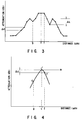
- Fig. 2 shows an example of attenuation change in the attenuator 9. This change is obtained when the acoustic lens 3 is moved from a position remote enough from the sample 5 to the sample 5 in the above-described case.
- the acoustic lens 3 is focused on the sample 5 near a distance (c).
- the strength of waves reflected from the sample near the focus point is quite large. It is, therefore, saturated by the pre-amplifier 7 to keep the attenuation at a certain value for a certain time period.
- Maximum points represented by (a) and (e) are created by noise and other factors.
- the acoustic lens 3 is moved little, by little from a position remote enough to the sample 5 to gain automatic focus. Every distance that the lens 3 is moved, the computer 14 adjusts the attenuation of the attenuator 9 to change the signal outputted by the comparator 11 from "ON" to "OFF". The largest attenuation seen until the lens 3 comes to the now-position is stored in the memory of the computer 14 and when the attenuation now seen is larger than that stored, the attenuation stored is updated. This updating of attenuation is repeated and every time the updating of attenuation is repeated, the position of the acoustic lens 3 is stored.
- the memory in the computer 14 is not updated but the acoustic lens 3 is further moved nearer to the sample 5.
- the following formula is used together with a value previously set in the memory of the computer 14. (attenuation now seen) ⁇ (attenuation stored) - (set value) wherein the set value is intended to remove the influence of noise, as shown in Fig. 2, and it is set equal to or a little larger than a difference ⁇ L between attenuations at the distances (e) and (d). This set value is determined by examining noise characteristics and by other procedures.
- the acoustic lens 3 is still further moved nearer to the sample 5. And, when the condition is satisfied, the movement of the acoustic lens 3 is stopped.
- That position of the acoustic lens 3 which corresponds to the attenuation stored in the memory of the computer 14 is (f) in Fig. 3 which is near to the focus point and at which the attenuation begins to become certain.
- that position at which the acoustic lens 3 is stopped is (g) in Fig. 3 where the attenuation becomes smaller than a value obtained by subtracting the set value from the largest attenuation.
- the focus position (c) is between the distances (f) and (g) at all times.
- Fig. 4 shows the focus position (c′) obtained by the approximation.
- the attenuation at this focus position (c′) is larger than that at the distance (f) but smaller than the smallest step ( ⁇ l in Fig. 3) of the changing values of the attenuation.
- the attenuation at the focus position (c′) is that value obtained by adding the one step of changing attenuations to the attenuation at the distance (f) and that the attenuation at the distance (g) is a value obtained by subtracting the above set value from the attenuation stored when the movement of the acoustic lens 3 is stopped.
- the focus position (c′) at this time can be approximated by a secondary curve passing through points G and F and contacting a line (m), as shown in Fig. 4. Because the focus position (c′) can be calculated by this approximation, automatic focus adjustment is finished when the acoustic lens 3 is moved to the position (c′).
- the acoustic lens 3 When the acoustic lens 3 is operated as described above, it is focused on the sample 5. Further, the attenuation is set to be the largest and the gating width is adjusted to a previously-determined one. While shifting little by little the timing at which the gating is carried out, the gating position at which the output signal applied from the comparator 11 is "ON" is then detected. Here the previously-determined gating width is made so narrow as to cover only those of the sample-reflected waves which are reflected by the surface of the sample.
- the wave components reflected from near the expected focus point on the sample 5 are picked up and the attenuation is adjusted to bring the input/output ratio of the attenuator 9 to a desirable value when the acoustic lens 3 is moved.
- the attenuating curve thus obtained enables the focus position to be obtained. Therefore, the focus position can be more easily detected without setting the threshold value near the strength of that wave reflected when the acoustic lens 3 is at its focus point, as seen in the conventional cases.
- the focus adjustment of the acoustic lens 3 can be therefore made extremely easier, thereby enhancing the workability of forming the ultrasonic image of any sample to a greater extent.
- the focus position (c′) can be thus obtained.
- the shape of a changing attenuation curve is determined by the frequency of the acoustic lens 3 and its angular aperture. When the attenuating curve is previously measured, therefore, the focus position can be obtained by the shape of the curve and by measuring two points in the same manner as in the above case.
- any acoustic lens of the same kind as the above-mentioned one can be used even if it is different in working distance. Furthermore, when the set value is adjusted, the automatic focusing can be achieved even if waves transmitted to the sample 5 are of the burst type.
- the attenuation of the attenuator 9 has been controlled by the computer 14, a control circuit for feeding outputs of the comparator 11 back to the attenuator 9 may be used.
- the ultrasonic microscope of the present invention it is unnecessary for the operator to adjust the threshold value every time the sample is replaced by a new one and the automatic focusing can be more easily adjusted, thereby enhancing the workability of the microscope to a greater extent.
Landscapes
- Physics & Mathematics (AREA)
- Engineering & Computer Science (AREA)
- Remote Sensing (AREA)
- Radar, Positioning & Navigation (AREA)
- Acoustics & Sound (AREA)
- General Physics & Mathematics (AREA)
- Computer Networks & Wireless Communication (AREA)
- Biochemistry (AREA)
- General Health & Medical Sciences (AREA)
- Analytical Chemistry (AREA)
- Immunology (AREA)
- Pathology (AREA)
- Chemical & Material Sciences (AREA)
- Life Sciences & Earth Sciences (AREA)
- Health & Medical Sciences (AREA)
- Multimedia (AREA)
- Investigating Or Analyzing Materials By The Use Of Ultrasonic Waves (AREA)
Claims (2)
- Ultraschallmikroskop bei dem durch eine akustische Linse (3) gebündelt Ultraschallwellen auf eine Probe (5) geführt werden, von der Probe (5) reflektierte Wellen empfangen und in empfangene elektrische Signale umgewandelt werden und das Ultraschallwellenbild der Probe (5) unter Verwendung der empfangenen elektrischen Signale gebildet wird, mita) einer Einrichtung (15) zum Variieren des Abstandes der akustischen Linse (3) von der Probe (5)b) einer Einrichtung (7, 8, 14, 18, 19) zum Aufnehmen derjenigen empfangenen elektrischen Signale, die einem Teil der von der Probe (5) reflektierten Signale entsprechen; gekennzeichnet durchc) ein Dämpfungselement (9) zum Empfangen eines von der Aufnehme-Einrichtung (7, 8, 14, 18, 19) ausgegebenen Signals,d) eine Einrichtung (11, 13) zum Vergleichen eines Signals, das in Bezug zu dem von dem Dämpfungselement (9) ausgegebenen Signalen steht, mit einem zuvor eingestellten Schwellenwert, um ein EIN-Ausgangssignal zu erzeugen, wenn der Schwellenwert überschritten ist,e) eine Verstärkungs- bzw. Dämpfungsregelung (14) zum Einstellen der Dämpfung des Dämpfungselements (9) auf der Basis von Vergleichswerten, die durch die Vergleichseinrichtung (11, 13) ermittelt worden sind, wodurch das Eingangs/Ausgangs-Verhältnis des Dämpfungselements (9) geändert wird, um ein EIN-Ausgangssignal der Vergleichseinrichtung (11, 13) in ein AUS-Ausgangssignal abzuändern, undf) eine Fokusjustierregelungseinrichtung (14, 16) zum Berechnen der Position des Brennpunktes der akustischen Linse (3) auf der Basis einer Verstärkungsänderungskurve, die sich ergibt, wenn die akustische Linse (3) von einer nicht-fokussierten Lage in Richtung der Probe (5) bewegt wird, und zum Ausgeben eines Steuersignals zu der Abstandsveränderungseinrichtung (15) als Antwort auf das Ergebnis der Berechnung.
- Das Ultraschallmikroskop nach Anspruch 1, worin die Aufnehme-Einrichtung (7, 8, 14, 18, 19) eine Gattersektion (8) zum Aufnehmen nur der Signale umfaßt, die von einem Nahbereich um einen erwarteten Brennpunkt auf der Probe (5) reflektierten Wellen entsprechen, und eine Einrichtung (19) zum Einstellen der Gattertaktzeit der Gattersektion (8) als Antwort auf ein von dem Regler (14) herrührendes Signal umfaßt.
Applications Claiming Priority (3)
| Application Number | Priority Date | Filing Date | Title |
|---|---|---|---|
| JP238010/90 | 1990-09-07 | ||
| JP2238010A JPH04116458A (ja) | 1990-09-07 | 1990-09-07 | 超音波顕微鏡 |
| PCT/JP1991/001191 WO1992004628A1 (fr) | 1990-09-07 | 1991-09-07 | Microscope ultrasonore |
Publications (3)
| Publication Number | Publication Date |
|---|---|
| EP0502199A1 EP0502199A1 (de) | 1992-09-09 |
| EP0502199A4 EP0502199A4 (en) | 1993-05-05 |
| EP0502199B1 true EP0502199B1 (de) | 1994-12-28 |
Family
ID=17023806
Family Applications (1)
| Application Number | Title | Priority Date | Filing Date |
|---|---|---|---|
| EP91915620A Expired - Lifetime EP0502199B1 (de) | 1990-09-07 | 1991-09-07 | Ultraschallmikroskop |
Country Status (5)
| Country | Link |
|---|---|
| US (1) | US5553499A (de) |
| EP (1) | EP0502199B1 (de) |
| JP (1) | JPH04116458A (de) |
| DE (1) | DE69106339T2 (de) |
| WO (1) | WO1992004628A1 (de) |
Families Citing this family (9)
| Publication number | Priority date | Publication date | Assignee | Title |
|---|---|---|---|---|
| US6544179B1 (en) | 2001-12-14 | 2003-04-08 | Koninklijke Philips Electronics, Nv | Ultrasound imaging system and method having automatically selected transmit focal positions |
| DE202006020869U1 (de) * | 2005-04-11 | 2010-09-02 | Pva Tepla Analytical Systems Gmbh | Akustisches Rastermikroskop |
| US7947076B2 (en) * | 2005-06-03 | 2011-05-24 | Medtronic Xomed, Inc. | Nasal valve treatment method and apparatus |
| US7520172B2 (en) * | 2005-09-07 | 2009-04-21 | The Boeing Company | Inspection system for inspecting a structure and associated method |
| US9625572B2 (en) | 2011-11-18 | 2017-04-18 | Sonix, Inc. | Method and apparatus for signal path equalization in a scanning acoustic microscope |
| KR102207211B1 (ko) | 2014-10-27 | 2021-01-25 | 삼성전자주식회사 | 검사 장치, 및 이를 포함하는 영상 장치 |
| US12510644B2 (en) * | 2018-05-25 | 2025-12-30 | Pva Tepla Analytical Systems Gmbh | Ultrasonic microscope and carrier for carrying an acoustic pulse transducer |
| CN112630306B (zh) * | 2020-08-20 | 2023-08-01 | 中国科学院大学 | 一种基于超声显微镜点聚焦换能器的自动对焦方法和系统 |
| JP2024011846A (ja) * | 2022-07-15 | 2024-01-25 | 株式会社アドバンテスト | 超音波測定装置、方法、プログラム、記録媒体 |
Family Cites Families (5)
| Publication number | Priority date | Publication date | Assignee | Title |
|---|---|---|---|---|
| JPS5839942A (ja) * | 1981-09-03 | 1983-03-08 | Olympus Optical Co Ltd | 超音波顕微鏡の自動焦点調節装置 |
| US4541281A (en) * | 1983-04-03 | 1985-09-17 | Noriyoshi Chubachi | Ultrasonic microscope system |
| JPS61259170A (ja) * | 1985-05-14 | 1986-11-17 | Olympus Optical Co Ltd | 超音波顕微鏡における試料の傾き調整装置 |
| JPS62249054A (ja) * | 1986-04-22 | 1987-10-30 | Olympus Optical Co Ltd | 超音波顕微鏡 |
| DE3835886A1 (de) * | 1988-10-21 | 1990-04-26 | Leitz Wild Gmbh | Zeitfensterautomatik fuer ultraschallmikroskop |
-
1990
- 1990-09-07 JP JP2238010A patent/JPH04116458A/ja active Pending
-
1991
- 1991-09-07 EP EP91915620A patent/EP0502199B1/de not_active Expired - Lifetime
- 1991-09-07 DE DE69106339T patent/DE69106339T2/de not_active Expired - Fee Related
- 1991-09-07 WO PCT/JP1991/001191 patent/WO1992004628A1/ja not_active Ceased
-
1994
- 1994-09-02 US US08/300,064 patent/US5553499A/en not_active Expired - Fee Related
Also Published As
| Publication number | Publication date |
|---|---|
| EP0502199A1 (de) | 1992-09-09 |
| JPH04116458A (ja) | 1992-04-16 |
| EP0502199A4 (en) | 1993-05-05 |
| US5553499A (en) | 1996-09-10 |
| WO1992004628A1 (fr) | 1992-03-19 |
| DE69106339D1 (de) | 1995-02-09 |
| DE69106339T2 (de) | 1995-08-10 |
Similar Documents
| Publication | Publication Date | Title |
|---|---|---|
| EP0502199B1 (de) | Ultraschallmikroskop | |
| EP0064399A2 (de) | Ultraschallmessmethode | |
| US5513531A (en) | Ultrasonic system for measurement of thin layers | |
| US4577504A (en) | Acoustic microscope | |
| JP2002544491A (ja) | 車両周囲の対象物の検出装置 | |
| US5349862A (en) | Apparatus for measuring the velocity of ultrasonic sound in terms of V(Z) characteristics and ultrasonic microscope using that apparatus | |
| US5621173A (en) | Method and apparatus for non-contact determination of the weight per unit area of thin materials | |
| US5077695A (en) | Near field scanning acoustic microscope and method | |
| JPH06502924A (ja) | 超音波距離測定装置 | |
| US4472972A (en) | Ultrasound imaging system employing operator controlled filter for reflected signal attenuation compensation | |
| US4603585A (en) | Method for representing elastic parameters of object surfaces | |
| EP0039457B1 (de) | Akustisches Mikroskop | |
| JPH09243608A (ja) | 斜角探傷方法および装置 | |
| JP5055513B2 (ja) | 超音波アレイセンサシステムおよび遅延加算処理方法 | |
| JPH04326056A (ja) | 超音波顕微鏡 | |
| JPH09145696A (ja) | 欠陥深さ測定方法およびその装置 | |
| EP0032732A1 (de) | Ultraschall-Bildwiedergabesystem | |
| US4620443A (en) | Low frequency acoustic microscope | |
| JP4647864B2 (ja) | 超音波映像装置およびその測定方法 | |
| JPH08313498A (ja) | 超音波顕微鏡 | |
| JPH05333007A (ja) | 超音波測定装置 | |
| US11169118B2 (en) | Method for extending detection range of a structural health monitoring system | |
| JPH0798373A (ja) | レーザーレーダー装置 | |
| JPS6252572B2 (de) | ||
| JPH0461306B2 (de) |
Legal Events
| Date | Code | Title | Description |
|---|---|---|---|
| PUAI | Public reference made under article 153(3) epc to a published international application that has entered the european phase |
Free format text: ORIGINAL CODE: 0009012 |
|
| 17P | Request for examination filed |
Effective date: 19920609 |
|
| AK | Designated contracting states |
Kind code of ref document: A1 Designated state(s): DE GB |
|
| A4 | Supplementary search report drawn up and despatched |
Effective date: 19930317 |
|
| AK | Designated contracting states |
Kind code of ref document: A4 Designated state(s): DE GB |
|
| 17Q | First examination report despatched |
Effective date: 19930706 |
|
| GRAA | (expected) grant |
Free format text: ORIGINAL CODE: 0009210 |
|
| AK | Designated contracting states |
Kind code of ref document: B1 Designated state(s): DE GB |
|
| REF | Corresponds to: |
Ref document number: 69106339 Country of ref document: DE Date of ref document: 19950209 |
|
| PG25 | Lapsed in a contracting state [announced via postgrant information from national office to epo] |
Ref country code: GB Effective date: 19950907 |
|
| PLBE | No opposition filed within time limit |
Free format text: ORIGINAL CODE: 0009261 |
|
| STAA | Information on the status of an ep patent application or granted ep patent |
Free format text: STATUS: NO OPPOSITION FILED WITHIN TIME LIMIT |
|
| 26N | No opposition filed | ||
| GBPC | Gb: european patent ceased through non-payment of renewal fee |
Effective date: 19950907 |
|
| PGFP | Annual fee paid to national office [announced via postgrant information from national office to epo] |
Ref country code: DE Payment date: 19960913 Year of fee payment: 6 |
|
| PG25 | Lapsed in a contracting state [announced via postgrant information from national office to epo] |
Ref country code: DE Free format text: LAPSE BECAUSE OF NON-PAYMENT OF DUE FEES Effective date: 19980603 |