EP0500984A1 - Drive unit with four limit switches - Google Patents
Drive unit with four limit switches Download PDFInfo
- Publication number
- EP0500984A1 EP0500984A1 EP91102918A EP91102918A EP0500984A1 EP 0500984 A1 EP0500984 A1 EP 0500984A1 EP 91102918 A EP91102918 A EP 91102918A EP 91102918 A EP91102918 A EP 91102918A EP 0500984 A1 EP0500984 A1 EP 0500984A1
- Authority
- EP
- European Patent Office
- Prior art keywords
- limit switches
- base plate
- drive unit
- unit according
- housing
- Prior art date
- Legal status (The legal status is an assumption and is not a legal conclusion. Google has not performed a legal analysis and makes no representation as to the accuracy of the status listed.)
- Granted
Links
Images


Classifications
-
- E—FIXED CONSTRUCTIONS
- E05—LOCKS; KEYS; WINDOW OR DOOR FITTINGS; SAFES
- E05F—DEVICES FOR MOVING WINGS INTO OPEN OR CLOSED POSITION; CHECKS FOR WINGS; WING FITTINGS NOT OTHERWISE PROVIDED FOR, CONCERNED WITH THE FUNCTIONING OF THE WING
- E05F15/00—Power-operated mechanisms for wings
- E05F15/60—Power-operated mechanisms for wings using electrical actuators
- E05F15/603—Power-operated mechanisms for wings using electrical actuators using rotary electromotors
-
- E—FIXED CONSTRUCTIONS
- E05—LOCKS; KEYS; WINDOW OR DOOR FITTINGS; SAFES
- E05Y—INDEXING SCHEME RELATING TO HINGES OR OTHER SUSPENSION DEVICES FOR DOORS, WINDOWS OR WINGS AND DEVICES FOR MOVING WINGS INTO OPEN OR CLOSED POSITION, CHECKS FOR WINGS AND WING FITTINGS NOT OTHERWISE PROVIDED FOR, CONCERNED WITH THE FUNCTIONING OF THE WING
- E05Y2400/00—Electronic control; Power supply; Power or signal transmission; User interfaces
- E05Y2400/10—Electronic control
- E05Y2400/30—Electronic control of motors
- E05Y2400/32—Position control, detection or monitoring
- E05Y2400/35—Position control, detection or monitoring related to specific positions
- E05Y2400/354—End positions
Definitions
- the corresponding electric drive units To automatically open gates, the corresponding electric drive units must be installed at a different location depending on the function of the gate and connected to the gate with special connecting elements.
- the limit switches can either be arranged in the area of the gate and actuated directly by it, or can be provided within a protected housing on the drive unit.
- the limit switches are protected from damage and dirt in the housing of the drive unit, but must be set precisely so that their triggering actually corresponds to the desired end positions of the door to be moved.
- the second solution corresponds, for example, to the subject matter of European patent application EP 8812121.
- the entire drive unit is accommodated in a housing which consists of a base plate and a cover.
- the base plate is screwed to the ceiling and has integrally formed with the base plate spacers, so that the chain drive pinion including the rail in which the chain rotates is housed in the distance between the base plate and the ceiling.
- all elements of the drive unit are mounted, for example an electric motor-gear unit, the output shaft of which extends through an opening in the base plate out of the housing, i.e. in the direction of the ceiling of the building, and with the sprocket driving the chain is connected.
- the nuts on the threaded spindle are prevented from rotating by an angle screwed onto the base plate next to the threaded spindle, one leg of which is located directly next to the nuts. Through elongated holes in the angle transverse to the longitudinal direction of the threaded spindle, it can be brought into contact with the nuts and adjusted without any problems.
- control electronics instead of limit switches, which are switched by mechanical elements that move depending on the gate, which is programmed, for example, for a certain operating time, which is used to move the gate from the fully open to the fully closed position and vice versa is necessary.
- the drive unit's time required to move the door from one setting to the other is not always the same, but depends, among other things. from the operating temperature of the drive unit, that is to say, for example, the ambient temperature, and also from its frictional losses, which can increase with increasing contamination, damage, etc. Fluctuations in the mains voltage are also responsible for a different operating time.
- time-dependent circuits can be used somewhat better for this phase, since with a certain one percentage deviation of the time setpoint, the absolute time difference is relatively small.
- the threaded spindle cannot be made long enough to arrange all limit switches on the same side of the threaded spindle, as in the previously known solution, even with four limit switches.
- the distance between the base plate and the ceiling can be used to accommodate two limit switches.
- the advantage of accommodating the two limit switches acting from below is not only that no additional space is required on the upper side of the base plate, but also that the pockets formed in the base plate additionally serve to stiffen the base plate to accommodate these limit switches.
- the stiffening ribs, which are necessary anyway, are therefore only brought into such a position that they - together with a lower enclosure of the limit switches to increase the stability of these ribs - form a lateral guide for the limit switches.
- each individual limit switch being in turn precisely defined by corresponding paragraphs.
- This recess should be open at least on one of its end faces, which makes the manufacturing process easier.
- limit switches acting from below are not held in position by screwing but held from above by appropriate molded parts in contact with the circumferential surfaces of the pockets, spring plates preferably being used as holding parts which, when the other limit switches are screwed onto the base plate, between these limit switches and Base plate are laid and fixed with this. This also speeds up and makes the assembly process cheaper.
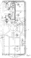
- FIG. 1 shows a drive unit 20 mounted on the ceiling with a base plate 1 to which all components of the drive unit 20 are fastened and which is screwed tightly to the ceiling.
- the cover 2 placed on the base plate 1 serves to protect these components from damage and contamination.
- the minimum distance A between the base plate and the ceiling which is determined by the spacers formed in one piece with the base plate 1, depends on the overall height of the pinion 7, the chain 18 driven thereby and the rail receiving this, which must find space between the base plate and the ceiling.
- the motor-gear unit 3 is screwed to the base plate 1 by means of its feet 4, the output shaft 5 extending through the opening 6 of the base plate into the space between the base plate 1 and the ceiling of the building and being connected there to the pinion 7 .
- the output shaft 5 is also connected to the coaxial socket 12 in a rotationally fixed manner by means of notched nails 26, so that the bevel gear teeth 13 of this socket 12 are located inside the housing, that is to say on the cover-side side of the base plate 1, and their rotation there on the bevel gear 14, which is on one end of the threaded spindle 9 sits, can transmit.
- the bevel pinion 14 and partly also the threaded spindle 9 are still below the motor-gear unit, for which the maximum distance F between the base plate and the motor-gear unit 4 is available, which is determined by the dimensions of this purchased part.
- this motor-gear unit 3 also determines the clear height B of the cover 2, which results in the total height C of the drive unit 20.
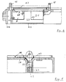
- the two upper limit switches 8 are located next to the threaded spindle 9, where they are screwed directly onto the base plate.
- the arm-like button of each limit switch ventilates slightly at an angle to the threaded rod and can be rotated about a vertical pivot axis 50 in the limit switch.
- the Limit switches are already fixed in their position for screwing by stops 29 projecting vertically from the base plate, a spring plate 22 additionally being placed between these limit switches 8 and the base plate 1 before screwing and being clamped during screwing, which enables the positioning of the screw below the threaded spindle 9 horizontal limit switch 8 is used.
- Fig. 2 also shows the position of the angle 16 which is screwed to the base plate on the free side of the threaded spindle 9.
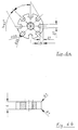
- this projection 23 does not reach the bottom of the slots 24 as far as possible, but only touches the inner contour of the slots 24 on its side surfaces in order to keep the friction between nuts 10 and angle 16 and thus the effort as low as possible.
- Each of the nuts 10 represents either one of the end positions of the door to be moved, or one of the points at which a switch from high speed to slow speed is carried out before the end position is reached.
- nuts 10 switches one of the limit switches 8 in each case.
- nuts 10 of different sizes can be used.
- the nuts 10 located on the outside of the threaded spindle 9 can have a smaller diameter than the nuts located on the inside, in order to be able to switch only the limit switch assigned to them and to be able to run over the button located further inside without contact.
- the nuts 10 are preferably plastic cylinders with relatively weakly rounded outer edges and a coaxial threaded bore 33 matched to the threaded spindle 9.
- a defined design of the outer edges 35 is necessary since this is the control edges for the push buttons 36 are the limit switches 8.
- the depth of the slots 24 must also be different, since the distance 34 of the bottom of the slots 24 from the center of the nut 10 must be the same, since the same projection 23 of the angle 16 approximately this bottom of the slots 24 must reach.
- the contact depth between the projection 23 and the inner surface of the slots 24 should be approximately 2 mm in depth, on the one hand to achieve a sufficiently secure blocking of the nuts and on the other hand to minimize the friction with respect to the angle 16.
- the angle 16 consists, in a manner known per se, of a leg resting on the base plate, in which two oblong holes 17 are arranged transversely to the longitudinal direction of the angle 16 for screwing to the base plate 1.
- the other leg 37 projects from this leg at a right angle, the stability of which is ensured by triangular struts 38 to the other leg.
- leg 37 protrudes from the side opposite the adjacent leg of the projection 23, which extends over the entire length of the angle 16, at such a height that it is in the assembled state of the angle 16 at the level of the axis of rotation of the threaded rod 9 comes to rest.
- the projection 23 is rounded at the free end.
- Fig. 3 shows a partial plan view of the base plate similar to Fig. 2, but without components attached to it.
- the depression 27 is formed by side walls 41 which are formed in one piece with the base plate 1 and are connected to one another at the bottom of the depression via a base 42 to increase the stability.
- the recess 27 has an end wall 43 on one side, which is connected to the bottom 42 and the side walls 41. This end wall 43 is located in the vicinity of the outer wall 44 of the base plate.
- the opposite end face of the recess 27 is largely open in order to make it easier to manufacture the base plate and to be able to lead cables underneath the base plate to the pockets 21.
- the side walls 41 are rounded on one side and obliquely on the other side into the base plate 1 in order to make it easy to insert the limit switches.
- 5 also shows the stops 29 projecting vertically upward from the base plate, between which the limit switches 8 screwed onto the base plate are placed for the purpose of assembly.
- the raised contact surface 28 can be seen in FIG. 5 and also in FIG. 3 in the area of each of these two limit switches 28.
- a spring plate 22 with a corresponding shape is placed in such a way that it follows the horizontal course of the contact surface 28 and its rounded transition into the recess 27 and ends there horizontally after a right-angled bend.
- This free end 46 presses when the limit switch 8 is inserted on its upper side, so that the spring plate no longer abuts the curve, as shown in FIG. 5.
Abstract
Description
Zum automatischen Öffnen von Toren müssen die entsprechenden elektrischen Antriebseinheiten je nach Funktion des Tores an einer anderen Stelle montiert und mit speziellen Verbindungselementen mit dem Tor verbunden werden.To automatically open gates, the corresponding electric drive units must be installed at a different location depending on the function of the gate and connected to the gate with special connecting elements.
Bei einem nach oben aufschwingenden Tor ist es beispielsweise bekannt, im Bereich der Decke eine Führungsschiene zu montieren, in der eine Antriebskette oder ein ähnliches Mittel umläuft, und einen Schlitten entlang dieser Führungsschiene bewegt. Dieser Schlitten ist über eine Führungsstange mit dem Torblatt verbunden, wodurch dieses geöffnet und geschlossen werden kann. Üblicherweise wird dabei das dem Tor abgewandte Ende der Kette mit Hilfe des Umlenkritzels durch eine elektrische Antriebseinheit, die an der Decke befestigt ist, angetrieben. Um die Bewegung der Kette und damit des Tores in den richtigen Endstellungen anzuhalten, sind Endschalter oder andere Elemente mit gleicher Wirkung notwendig.In the case of a gate swinging upwards, it is known, for example, to mount a guide rail in the area of the ceiling, in which a drive chain or a similar means rotates, and to move a carriage along this guide rail. This slide is connected to the door leaf via a guide rod, which means that it can be opened and closed. Usually the end of the chain facing away from the gate is driven with the aid of the deflection pinion by an electric drive unit which is attached to the ceiling. In order to stop the movement of the chain and thus the gate in the correct end positions, limit switches or other elements with the same effect are necessary.
Dabei können die Endschalter entweder im Bereich des Tores angeordnet und direkt durch dieses betätigt werden, oder innerhalb eines geschützten Gehäuses an der Antriebseinheit vorgesehen sein.The limit switches can either be arranged in the area of the gate and actuated directly by it, or can be provided within a protected housing on the drive unit.
Im ersteren Fall sind die Einstellarbeiten zum Erreichen der richtigen Endpositionen des Tores einfach durchzuführen, dafür besteht jedoch ein erhöhtes Beschädigungsrisiko für diese Endschalter, und zusätzlich müssen Leitungen von den Endschaltern zur Antriebseinheit verlegt werden.In the former case, the adjustment work to achieve the correct end positions of the door is easy to carry out, but there is an increased risk of damage to these limit switches, and cables must also be laid from the limit switches to the drive unit.
Im zweiten Fall sind die Endschalter vor Beschädigungen und Verschmutzung geschützt im Gehäuse der Antriebseinheit untergebracht, müssen jedoch genau eingestellt werden, damit ihre Auslösung tatsächlich mit den gewünschten Endpositionen des zu bewegenden Tores übereinstimmt.In the second case, the limit switches are protected from damage and dirt in the housing of the drive unit, but must be set precisely so that their triggering actually corresponds to the desired end positions of the door to be moved.
Der zweiten Lösung entspricht beispielsweise der Gegenstand der Europäischen Patentanmeldung EP 8812121. Dabei ist die gesamte Antriebseinheit in einem Gehäuse untergebracht, welches aus einer Grundplatte und einem Deckel besteht. Die Grundplatte wird dabei an der Decke verschraubt und weist einstückig mit der Grundplatte ausgebildete Abstandhalter auf, so daß das die Kette antreibende Ritzel einschließlich der Schiene, in der die Kette umläuft, in dem Abstand zwischen der Grundplatte und der Decke untergebracht ist.The second solution corresponds, for example, to the subject matter of European patent application EP 8812121. The entire drive unit is accommodated in a housing which consists of a base plate and a cover. The base plate is screwed to the ceiling and has integrally formed with the base plate spacers, so that the chain drive pinion including the rail in which the chain rotates is housed in the distance between the base plate and the ceiling.
Auf der der Decke abgewandten Seite der Grundplatte sind sämtliche Elemente der Antriebseinheit montiert, beispielsweise eine elektrische Motor-Getriebe-Einheit, deren Abtriebswelle sich durch eine Öffnung in der Grundplatte aus dem Gehäuse nach außen, also in Richtung der Decke des Gebäudes, erstreckt und mit dem die Kette antreibenden Ritzel verbunden ist.On the side of the base plate facing away from the ceiling, all elements of the drive unit are mounted, for example an electric motor-gear unit, the output shaft of which extends through an opening in the base plate out of the housing, i.e. in the direction of the ceiling of the building, and with the sprocket driving the chain is connected.
Noch innerhalb des Gehäuses wird die Drehbewegung der Antriebswelle auf eine parallel zur Grundplatte gelagerte Gewindespindel übertragen, auf welcher sich Muttern als Nocken befinden, die an einem Mitdrehen mit der Gewindespindel gehindert sind. Dadurch verschrauben sich diese Muttern bei einem Antrieb des Tores entlang der Gewindespindel, so daß nach einer einmal vorgenommenen Einstellung der Muttern auf der Gewindespindel eine bestimmte Axialposition auf der Gewindespindel jeweils einer bestimmten Position des Tores zuzuordnen ist.Even within the housing, the rotary motion of the drive shaft is transmitted to a threaded spindle mounted parallel to the base plate, on which there are nuts as cams that are prevented from rotating with the threaded spindle. As a result, these nuts are screwed together when the gate is driven along the threaded spindle, so that after the nuts on the threaded spindle have been set once, a specific axial position on the threaded spindle can be assigned to a specific position of the gate.
Die Muttern werden auf der Gewindespindel durch einen neben der Gewindespindel auf die Grundplatte aufgeschraubten Winkel, dessen einer Schenkel sich direkt neben den Muttern befindet, am Drehen gehindert. Durch Langlöcher in dem Winkel quer zur Längsrichtung der Gewindespindel kann dieser problemlos in Anlage an die Muttern gebracht und justiert werden.The nuts on the threaded spindle are prevented from rotating by an angle screwed onto the base plate next to the threaded spindle, one leg of which is located directly next to the nuts. Through elongated holes in the angle transverse to the longitudinal direction of the threaded spindle, it can be brought into contact with the nuts and adjusted without any problems.
Auf der dem Winkel gegenüberliegenden Seite der Gewindespindel sind zwei bekannte, elektromechanische Endschalter auf der Grundplatte verschraubt, deren Taster durch die entlang der Gewindestange sich bewegenden Muttern betätigt werden, von denen eine der geöffneten und die andere der geschlossenen Stellung des Tores entspricht.On the side of the threaded spindle opposite the angle, two known, electromechanical limit switches are screwed to the base plate, the buttons of which are actuated by the nuts moving along the threaded rod, one of which corresponds to the open and the other to the closed position of the gate.
Darüber hinaus ist es bekannt, anstelle von Endschaltern, die durch mechanische, in Abhängigkeit des Tores bewegte Elemente geschaltet werden, eine Steuerelektronik zu verwenden, welcher beispielsweise eine bestimmte Betriebszeit einprogrammiert ist, die zum Bewegen des Tores von der vollständig geöffneten bis zur vollständig geschlossenen Stellung und umgekehrt notwendig ist.In addition, it is known to use control electronics instead of limit switches, which are switched by mechanical elements that move depending on the gate, which is programmed, for example, for a certain operating time, which is used to move the gate from the fully open to the fully closed position and vice versa is necessary.
Der Einsatz solcher elektronischer Steuerungen hat sich nicht nur als teuerer erwiesen sondern auch als störanfälliger: Zum einen ist die notwendige Laufzeit der Antriebseinheit zum Bewegen des Tores von einer Einstellung in die andere nicht immer gleich, sondern hängt u.a. von der Betriebstemperatur der Antriebseinheit, also beispielsweise der Umgebungstemperatur, ab und darüber hinaus auch von deren Reibungsverlusten, die mit zunehmender Verschmutzung, Beschädigung etc. stärker werden können. Ebenso sind Schwankungen in der Netzspannung für eine unterschiedliche Betriebsdauer verantwortlich.The use of such electronic controls has not only proven to be more expensive but also more prone to failure: on the one hand, the drive unit's time required to move the door from one setting to the other is not always the same, but depends, among other things. from the operating temperature of the drive unit, that is to say, for example, the ambient temperature, and also from its frictional losses, which can increase with increasing contamination, damage, etc. Fluctuations in the mains voltage are also responsible for a different operating time.
Dabei ist zu beachten, daß bereits eine um nur 1 oder 2% falsche Betriebsdauer zu einem um einige cm geöffneten anstatt vollständig geschlossenem Tor führen kann, bzw. bei Weiterlaufen der Antriebseinheit nach dem vollständigen Schließen des Tores um nur wenige Sekunden zu einer Schädigung des Antriebsmotores führen kann.It should be noted that an incorrect operating time of just 1 or 2% can lead to a door that is opened a few cm instead of completely closed, or if the drive unit continues to run after only a few seconds, the drive motor is damaged by only a few seconds can lead.
Darüber hinaus ist eine mechanische Lösung wesentlich einfacher im Hinblick auf die Einstellbarkeit, was bei unterschiedlich qualifizierten Personen, die den Einbau und die Ersteinstellung bzw. die Nachstellung vorzunehmen haben, wünschenswert ist.In addition, a mechanical solution is much simpler in terms of adjustability, which is desirable for people with different qualifications who have to carry out the installation and initial adjustment or readjustment.
Insbesondere kann ein unterschiedliches Ergebnis zwischen den Einstellversuchen und dem Praxisbetrieb daher rühren, daß während des Einstellvorganges ein vielmaliges Öffnen und Schließen des Tores hintereinander durchgeführt wird, wodurch sich der Elektromotor, die Kette etc. im optimalen thermischen Betriebszustand befinden.In der Praxis wird die Antriebseinheit dagegen oftmals nur im 12-Stunden-Abstand betätigt und ist damit gerade in der Winterzeit wesentlich kälter. Gerade eine sehr genaue Einstellung mit wiederholten Versuchen führt daher in der Praxis nicht zum gewünschten Ergebnis des vollständigen Öffnens und v.a. vollständigen Schließen des Tores.In particular, a different result between the setting attempts and the practical operation can be attributed to the fact that the door is opened and closed many times in succession during the setting process, as a result of which the electric motor, the chain, etc. are in the optimal thermal operating state. In practice, the drive unit on the other hand, often only operated at 12-hour intervals and is therefore much colder, especially in winter. In practice, a very precise setting with repeated attempts does not lead to the desired result of full opening and, above all, complete closing of the gate.
Weiterhin ist es bekannt, bei derartigen Torantrieben das Tor nicht mit der gleichen Geschwindigkeit bis in seine Endstellung zu bewegen, sondern bereits kurz vor Erreichen dieser Einstellung die Betriebsgeschwindigkeit herabzusetzen, um eine Beschädigung zu vermeiden, indem die relativ große Masse des Tores mit Zu hoher Geschwindigkeit die Endstellung und damit eine Anlage an einen mechanischen Widerstand erreicht.Furthermore, it is known in such gate drives not to move the gate to its end position at the same speed, but to reduce the operating speed shortly before this setting is reached, in order to avoid damage by the relatively large mass of the gate at too high a speed reached the end position and thus an attachment to a mechanical resistance.
Da die Zeitdauer zwischen dem Erreichen des Punktes, an dem die Geschwindigkeit herabgesetzt werden soll, und dem Erreichen der Endstellung im Vergleich zur gesamten Dauer des Betriebsvorganges telativ kurz ist, kann für diese Phase bereits etwas besser mit zeitabhängigen Schaltungen gearbeitet werden, da bei einer gewissen prozentualen Abweichung des zeitlichen Sollwertes die absolute zeitliche Differenz relativ gering ausfällt.Since the time between reaching the point at which the speed is to be reduced and reaching the end position is telatively short compared to the entire duration of the operating process, time-dependent circuits can be used somewhat better for this phase, since with a certain one percentage deviation of the time setpoint, the absolute time difference is relatively small.
Aus diesem Grunde ist die Kombination zweier elektromechanischer Endschalter innerhalb des Gehäuses der Antriebseinheit mit einer zeitabhängigen elektronischen Steuerung für die Festlegung der Zeitdauer für die Langsamphase bekannt.For this reason, the combination of two electromechanical limit switches within the housing of the drive unit with a time-dependent electronic control for determining the time period for the slow phase is known.
Doch auch in diesem Fall ergibt sich die Schwierigkeit, daß eine solche zeitabhängige Steuerung dem Montierer bzw. Einsteller immer als "Blackbox" erscheint und bei falschem Betriebsergebnis nur schwierig zu korrigieren ist, da dies immer nur über die Verstellung der elektromechanischen Endschalter möglich ist. Liefert die elektronische Zeiteinheit selbst ein falsches Ergebnis, so kann diese nicht nachgestellt, sondern lediglich ausgetauscht werden, was nicht nur mit Kosten sondern auch meist einem längeren zeitlichen Nutzungsausfall verbunden ist.But even in this case there is the difficulty that such a time-dependent control always appears to the assembler or adjuster as a "black box" and is difficult to correct if the operating result is incorrect, since this is always only possible by adjusting the electromechanical limit switches. If the electronic time unit itself delivers a wrong result, it cannot be adjusted, but can only be exchanged, which is not only associated with costs but also usually with a longer loss of use.
Aus diesem Grund ist es wünschenswert, vollständig auf eine elektronische Steuerung in der Antriebseinheit zu verzichten, und sowohl die Einstellungen des Tores als auch den Beginn der langsam laufenden Phase durch mechanisch geschaltete Endschalter zu bewirken.For this reason, it is desirable to completely dispense with electronic control in the drive unit, and to effect both the setting of the gate and the start of the slow-running phase by means of mechanically switched limit switches.
Da die Drehbewegung der Gewindespindel von der Abtriebswelle der Motor-Getriebe-Einheit dort abgenommen wird, wo diese das Gehäuse verläßt, herrschen an der Gewindespindel sehr beengte Raumverhältnisse, da als Motor-Getriebe-Einheit ein Zukaufteil verwendet wird und damit der zwischen der Grundplatte und dem Motorkörper vorhandene Abstand bereits festliegt. Eine zusätzliche Vergrößerung dieses Abstandes ist darüber hinaus auch nicht erwünscht, da dies die Gesamtbauhöhe der Antriebseinheit vergrößern würde, was die Montage an bestimmten Einbauorten, wie etwa an einem Sturz eines Tores, also zwischen der Oberkante der Torhöhlung und der etwas höher liegenden Decke, erschweren oder unmöglich machen würde.Since the rotational movement of the threaded spindle is removed from the output shaft of the motor-gear unit where it leaves the housing, there is very limited space on the threaded spindle, since a purchased part is used as the motor-gear unit and thus between the base plate and the existing distance to the motor body is already fixed. An additional increase in this distance is also not desirable, since this would increase the overall height of the drive unit, which complicates the assembly at certain installation locations, such as at a lintel of a door, i.e. between the upper edge of the door cavity and the slightly higher ceiling or would make impossible.
Auf der anderen Seite kann die Gewindespindel nicht lang genug ausgebildet werden, um wie bei der bisher bekannten Lösung auch bei vier Endschaltern alle Endschalter auf der gleichen Seite der Gewindespindel anzuordnen.On the other hand, the threaded spindle cannot be made long enough to arrange all limit switches on the same side of the threaded spindle, as in the previously known solution, even with four limit switches.
Läßt man dagegen zwei der vier gewünschten Endschalter von der Unterseite der Grundplatte her, also im montierten Zustand von oben her, angreifen, so kann der zwischen der Grundplatte und der Decke vorhandene Abstand zum Unterbringen zweier Endschalter genutzt werden. Voraussetzung hierfür ist jedoch, daß das auf die Abtriebswelle aufgesetzte Ritzel, welches die Kette antreibt, einen so kleinen Durchmesser aufweist, daß die Kette nicht in den Bereich ragt, in dem die Endschalter sitzen müssen. Dies ist dann möglich, wenn die Drehgeschwindigkeit des Motors bzw. die Untersetzung der nachgeschalteten Getriebeeinheit im Hinblick auf ein möglichst kleines Ritzel abgestimmt ist.If, on the other hand, two of the four desired limit switches are attacked from the underside of the base plate, that is to say from above in the assembled state, the distance between the base plate and the ceiling can be used to accommodate two limit switches. A prerequisite for this, however, is that the pinion which is attached to the output shaft and which drives the chain has such a small diameter that the chain does not protrude into the area in which the limit switches are located have to. This is possible if the speed of rotation of the motor or the reduction of the downstream gear unit is coordinated with a view to the smallest possible pinion.
Der Vorteil einer Unterbringung der beiden von unten her angreifenden Endschalter liegt nicht nur darin, daß auf der Oberseite der Grundplatte kein zusätzlicher Raum benötigt wird, sondern auch darin, daß die in der Grundplatte geformten Taschen zur Aufnahme dieser Endschalter zusätzlich der Versteifung der Grundplatte dienen. Die ohnehin notwendigen Versteifungsrippen werden also lediglich in eine solche Position gebracht, daß sie - zusammen mit einer unteren Umschließung der Endschalter zur Vergrößerung der Stabilität dieser Rippen - eine seitliche Führung für die Endschalter bilden.The advantage of accommodating the two limit switches acting from below is not only that no additional space is required on the upper side of the base plate, but also that the pockets formed in the base plate additionally serve to stiffen the base plate to accommodate these limit switches. The stiffening ribs, which are necessary anyway, are therefore only brought into such a position that they - together with a lower enclosure of the limit switches to increase the stability of these ribs - form a lateral guide for the limit switches.
Für die Herstellung solcher Grundplatten im Spritzgußverfahren ist es weiterhin vorteilhaft, wenn die Endschalter nicht unmittelbar auf dem Grund der Taschen aufsitzen, da durch Ungenauigkeit des Spritzvorganges hier Unregelmäßigkeiten entstehen können. Deshalb werden diese Taschen tiefer ausgebildet, weisen jedoch entsprechende Absätze in dem Bereich auf, in dem die Endschalter aufsitzen.For the production of such base plates in the injection molding process, it is also advantageous if the limit switches are not seated directly on the bottom of the pockets, since irregularities can arise here due to inaccuracy of the injection molding process. For this reason, these pockets are made deeper, but have corresponding heels in the area in which the limit switches are seated.
Aus Gründen der Herstellbarkeit ist es weiter vorteilhaft, diese beiden Taschen zu einer gemeinsamen Vertiefung zusammenzufassen, wobei wiederum durch entsprechende Absätze die Positionierung jedes einzelnen Endschalters genau festgelegt ist. Diese Vertiefung sollte wenigstens auf einer ihrer Stirnseiten offen sein, was den Herstellungsprozess einfacher gestaltet.For reasons of manufacturability, it is further advantageous to combine these two pockets into a common depression, the positioning of each individual limit switch being in turn precisely defined by corresponding paragraphs. This recess should be open at least on one of its end faces, which makes the manufacturing process easier.
Diese von unten angreifenden Endschalter werden nicht durch Verschraubung in ihrer Position gehalten sondern von oben durch entsprechende Formteile in Anlage an den Umfangsflächen der Taschen gehalten, wobei vorzugsweise als Halteteile Federbleche verwendet werden, die beim Verschrauben der anderen Endschalter auf der Grundplatte zwischen diese Endschalter und die Grundplatte gelegt und mit dieser fixiert werden. Dadurch wird auch der Montagevorgang beschleunigt und verbilligt.These limit switches acting from below are not held in position by screwing but held from above by appropriate molded parts in contact with the circumferential surfaces of the pockets, spring plates preferably being used as holding parts which, when the other limit switches are screwed onto the base plate, between these limit switches and Base plate are laid and fixed with this. This also speeds up and makes the assembly process cheaper.
Um den Betätigungszeitpunkt der Taster der Endschalter möglichst genau festlegen zu können, werden als Nocken nicht die bisher bekannten handelsüblichen Sechskantmuttern auf der Gewindespindel verwendet, da diese neben den gerundeten Kanten zu große Fertigungsungenauigkeiten aufweisen. Statt dessen werden speziell gestaltete Kunststoffmuttern verwendet, die nicht nur eine exakt rechtwinklige Anlaufkante besitzen, sondern darüber hinaus auch regelmäßig über den Umfang verteilt in Längsrichtung angeordnete Schlitze aufweisen, in welche zum Verhindern des Mitdrehens ein entsprechender Fortsatz des neben der Gewindespindel aufgeschraubten Fixierungswinkels eingreift. Da aufgrund seiner Langlöcher dieser Winkel stufenlos in seinem Abstand zur Gewindespindel variiert werden kann, ist es möglich, den Fortsatz nur so weit in die Schlitze der Muttern hineinragen zu lassen, daß dieser nicht deren Grund erreicht. Dadurch wird eine wesentlich geringere Gleitreibung zwischen Muttern und Führungswinkel erzielt als bei vollflächiger Anlage eines Schenkels des Winkels an einer Seite einer Sechskantmutter.In order to be able to determine the actuation time of the pushbuttons of the limit switches as precisely as possible, the previously known commercially available hexagon nuts on the threaded spindle are not used as cams, since these have excessive manufacturing inaccuracies in addition to the rounded edges. Instead, specially designed plastic nuts are used, which not only have an exactly right-angled leading edge, but also regularly have slots arranged in the longitudinal direction distributed over the circumference, in which a corresponding extension of the fixing angle screwed on next to the threaded spindle engages to prevent rotation. Since due to its elongated holes this angle can be varied continuously in its distance from the threaded spindle, it is possible to let the extension protrude only so far into the slots of the nuts that it does not reach the bottom thereof. This results in a significantly lower sliding friction between the nuts and the guide bracket than when one of the brackets of the bracket is in full contact on one side of a hexagon nut.
Ist dagegen aus bestimmten Gründen, beispielsweise einer notwendigen Vergrößerung des Kettenritzels oder ähnlichem, eine Unterbringung der zwei Endschalter unterhalb der Gewindespindel nicht möglich, so können je zwei der Endschalter beidseits der Gewindespindel auf der Grundplatte verschraubt werden. Die Drehsicherung für die auf der Gewindestange laufenden Muttern muß dann jedoch oberhalb oder unterhalb der Gewindespindel angeordnet werden. Eine besonders einfache Lösung ist dabei das Einschieben eines entsprechend dimensionierten Stabes durch die Lagerböcke der Gewindespindel hindurch in einem solchen Abstand zur Gewindespindel, daß dieser Stab in den Schlitzen der Mutter zum Liegen kommt. Da die Gewindespindel in der Nähe der Außenkante der Grundplatte endet, kann ein solcher Stab nach Abnahme des Deckels von der Grundplatte leicht aus den Lagerböcken der Gewindespindel herausgezogen werden.If, on the other hand, it is not possible for certain reasons, for example a necessary enlargement of the chain sprocket or the like, to accommodate the two limit switches below the threaded spindle, two of the limit switches can be screwed onto the base plate on both sides of the threaded spindle. The anti-rotation device for the nuts running on the threaded rod must then be arranged above or below the threaded spindle. A particularly simple solution is the insertion of an appropriately dimensioned rod through the bearing blocks of the threaded spindle at such a distance from the threaded spindle that this rod comes to rest in the slots in the nut. Since the threaded spindle ends near the outer edge of the base plate, such a rod can be easily pulled out of the bearing blocks of the threaded spindle after the cover has been removed from the base plate.
Durch eine Kröpfung dieses Stabes an dem der Kante der Grundplatte benachbarten Ende wird verhindert, daß der Stab sich zu weit nach innen bewegt und nicht mehr durch beide Lagerböcke gehalten wird. Ein selbsttätiges Herausbewegen ist ebenfalls nicht möglich, da dies durch den aufgesetzten Deckel verhindert wird.By cranking this rod at the end adjacent to the edge of the base plate, it is prevented that the rod moves too far inwards and is no longer held by both bearing blocks. An automatic removal is also not possible, as this is prevented by the cover attached.
Eine Ausführungsform gemäß der Erfindung ist anhand der Figurenbeschreibung näher beschrieben. Es zeigen:
- Fig. 1
- eine Querschnittsdarstellung durch eine an der Decke montierte Antriebseinheit,
- Fig. 2
- eine teilweise Aufsicht auf die Grundplatte bei montierten Endschaltern,
- Fig. 3
- eine Aufsicht ähnlich der Fig. 2 auf eine leere Grundplatte,
- Fig. 4
- eine Schnittdarstellung der Vertiefung für die Endschalter,
- Fig. 5
- eine Schnittdarstellung rechtwinklig zur Darstellung der Fig. 4,
- Fig. 6a,b
- eine Darstellung der Mutter und
- Fig. 7a,b,c,d
- eine Darstellung des Verriegelungswinkels.
- Fig. 1
- 2 shows a cross-sectional representation through a drive unit mounted on the ceiling,
- Fig. 2
- a partial view of the base plate with the limit switches installed,
- Fig. 3
- 2 shows a top view similar to FIG. 2 on an empty base plate,
- Fig. 4
- a sectional view of the recess for the limit switch,
- Fig. 5
- 4 shows a sectional illustration at right angles to the illustration in FIG. 4,
- 6a, b
- a representation of the mother and
- 7a, b, c, d
- a representation of the locking angle.
Fig. 1 zeigt eine an der Decke montierte Antriebseinheit 20 mit einer Grundplatte 1, an der alle Komponenten der Antriebseinheit 20 befestigt sind, und welche mit der Decke fest verschraubt ist.1 shows a
Der auf die Grundplatte 1 aufgesetzte Deckel 2 dient dem Schutz dieser Komponenten vor Beschädigung und Verschmutzung. Der Mindestabstand A zwischen der Grundplatte und der Decke, der durch die einstückig mit der Grundplatte 1 ausgebildeten Abstandshalter bestimmt ist, hängt von der Bauhöhe des Ritzels 7, der hierdurch angetriebenen Kette 18 und der diese aufnehmenden Schiene ab, die zwischen der Grundplatte und der Decke Platz finden müssen.The
Die Motor-Getriebe-Einheit 3 ist mittels ihrer Füsse 4 auf der Grundplatte 1 verschraubt, wobei sich die Abtriebswelle 5 durch die Öffnung 6 der Grundplatte in den Zwischenraum zwischen Grundplatte 1 und der Decke des Gebäudes hinaus erstreckt und dort mit dem Ritzel 7 verbunden ist.The motor-
Dabei ist mit der Abtriebswelle 5 auch die koaxiale Buchse 12 mittels Kerbnägel 26 drehfest verbunden, so daß sich die Kegelradverzahnung 13 dieser Buchse 12 innerhalb des Gehäuses, also auf der deckelseitigen Seite der Grundplatte 1 befindet und ihre Drehung dort auf das Kegelrad 14, welches auf einer Stirnseite der Gewindespindel 9 sitzt, übertragen kann. Das Kegelritzel 14 und teilweise auch die Gewindespindel 9 befinden sich dabei noch unterhalb der Motor-Getriebe-Einheit, wofür maximal der Abstand F zwischen der Grundplatte und der Motor-Getriebe-Einheit 4 zur Verfügung steht, der durch die Abmessungen dieses Zukaufteiles festgelegt ist.The
Vor allem die Bauhöhe dieser Motor-Getriebe-Einheit 3 bestimmt darüber hinaus die lichte Höhe B des Deckels 2, woraus sich die Gesamthöhe C der Antriebs-Einheit 20 ergibt.Above all, the overall height of this motor-
Im montierten Zustand der Fig. 1 befinden sich oberhalb der Gewindespindel 9, die insgesamt 4 Muttern 10 aufweist, zwei Endschalter 8, und auch in entsprechenden Taschen 21 einer gemeinsamen Vertiefung 27 unter der Gewindestange, in der sie durch ein Federblech 22 gehalten werden (in Fig. 1 nicht eingezeichnet).In the assembled state of FIG. 1 there are two
Wie in der Aufsicht der Figur 2 besser zu erkennen ist, befinden sich die beiden oberen Endschalter 8 neben der Gewindespindel 9, wo sie direkt auf die Grundplatte aufgeschraubt werden. Der Arm-artige Taster jedes Endschalters verläüft dabei leicht schräg zur Gewindestange und ist um eine senkrecht stehende Schwenkachse 50 im Endschalter drehbar. Die Endschalter sind bereits für das Verschrauben durch senkrecht von der Grundplatte aufragende Anschläge 29 in ihrer Position festgelegt, wobei zusätzlich vor dem Verschrauben ein Federblech 22 zwischen diese Endschalter 8 und die Grundplatte 1 gelegt und beim verschrauben festgeklemmt wird, welches dem Positionieren der unterhalb der Gewindespindel 9 liegenden Endschalter 8 dient.As can be seen better in the top view of FIG. 2, the two
Fig. 2 zeigt auch die Lage des Winkels 16, der auf der freien Seite der Gewindespindel 9 auf der Grundplatte verschraubt ist.Fig. 2 also shows the position of the
Mit Hilfe der Langlöcher 17 in dem auf der Grundplatte 1 aufliegenden Schenkel des Winkels 16 kann dieser vor dem Festziehen der Schrauben 30 soweit an die Gewindespindel 9 herangeschoben werden, daß der längsverlaufende Vorsprung 23, der vom senkrecht von der Grundplatte 1 abstrebenden Schenkel aus in Richtung auf die Gewindestange 9 vorsteht, in die Schlitze 24 der Muttern 10 in gewünschter Weise eingreift.With the help of the
Dabei ist beabsichtigt, daß dieser Vorsprung 23 möglichst nicht den Grund der Schlitze 24 erreicht, sondern nur an seinen Seitenflächen die Innenkontur der Schlitze 24 berührt, um die Reibung zwischen Muttern 10 und Winkel 16 und damit den Kraftaufwand möglichst gering zu halten.It is intended that this
Jede der Muttern 10 stellt dabei entweder eine der Endpositionen des zu bewegenden Tores dar, oder einen der Punkte, bei welchen vor Erreichen der Endposition ein Umschalten vom Schnellauf auf den Langsamlauf vollzogen wird.Each of the nuts 10 represents either one of the end positions of the door to be moved, or one of the points at which a switch from high speed to slow speed is carried out before the end position is reached.
Damit schaltet jeweils eine der Muttern 10 jeweils einen der Endschalter 8. Um gegenseitige Behinderungen zu vermeiden, also beispielsweise Einschalten eines Endschalters durch die falsche Mutter 10, können unterschiedlich große Muttern 10 verwendet werden. Dabei können beispielsweise die auf der Gewindespindel 9 aussen liegenden Muttern 10 einen geringeren Durchmesser als die innen liegenden Muttern haben, um dadurch nur den ihnen zugeordneten Endschalter schalten zu können, den weiter innen liegenden Taster dagegen kontaktfrei überfahren zu können.In this way, one of the nuts 10 switches one of the
Wie am besten die Fig. 6a und 6b zeigen, sind die Muttern 10 vorzugsweise aus Kunststoff bestehende Zylinder mit relativ schwach gerundeten Außenkanten und einer auf die Gewindespindel 9 abgestimmten, koaxialen Gewindebohrung 33. Eine definierte Gestaltung der Außenkanten 35 ist notwendig, da dies die Steuerkanten für die Taster 36 der Endschalter 8 sind. Bei Verwendung von Muttern 10 mit unterschiedlichem Außendurchmesser muß auch die Tiefe der Schlitze 24 unterschiedlich sein, da der Abstand 34 des Grundes der Schlitze 24 von der Mitte der Mutter 10 gleich sein muß, da der gleiche Vorsprung 23 des Winkels 16 annähernd diesen Grund der Schlitze 24 erreichen muß. Bei einer Herstellung der Muttern 10 aus Polyamid sollte die Anlagetiefe zwischen dem Vorsprung 23 und der Innenfläche der Schlitze 24 etwa 2 mm in der Tiefe betragen, um einerseits eine ausreichend sichere Blockierung der Muttern zu erreichen und andererseits die Reibung gegenüber dem Winkel 16 zu minimieren.As best shown in FIGS. 6a and 6b, the nuts 10 are preferably plastic cylinders with relatively weakly rounded outer edges and a coaxial threaded bore 33 matched to the threaded
Wie Fig. 7 zeigt besteht der Winkel 16 in an sich bekannter Weise aus einem auf der Grundplatte aufliegenden Schenkel, in dem quer zur Längsrichtung des Winkels 16 zwei Langlöcher 17 zum Verschrauben mit der Grundplatte 1 angeordnet sind. Von diesem Schenkel ragt im rechten Winkel der andere Schenkel 37 auf, dessen Stabilität über dreieckige Verstrebungen 38 zum anderen Schenkel hin gesichert ist.As shown in FIG. 7, the
Von diesem Schenkel 37 ragt von der dem benachbarten Schenkel gegenüberliegenden Seite der Vorsprung 23 weg, der sich über die gesamte Länge des Winkels 16 erstreckt, und zwar in einer solchen Höhe, daß er im montierten Zustand des Winkels 16 auf der Höhe der Drehachse der Gewindestange 9 zu liegen kommt. Der Vorsprung 23 ist am freien Ende gerundet.From this
Fig. 3 zeigt eine teilweise Aufsicht auf die Grundplatte ähnlich der Fig. 2, jedoch ohne darauf befestigter Bauteile.Fig. 3 shows a partial plan view of the base plate similar to Fig. 2, but without components attached to it.
Zwischen den Lagerböcken 15, in denen die Gewindestange 9 geführt wird, ist die Vertiefung 27 zu erkennen, die in ihren Endbereichen aufgeweitet ist und durch die dabei entstehenden Absätze 32 die Taschen 21 zur Aufnahme der beiden unter der Gewindestange 9 liegenden Endschalter bildet.Between the bearing blocks 15, in which the threaded
Wie besser in der Querschnittsdarstellung der Fig. 5 zu erkennen, wird die Vertiefung 27 durch Seitenwände 41 gebildet, die einstückig mit der Grundplatte 1 ausgebildet sind und im Grunde der Vertiefung über einen Boden 42 zur Vergrößerung der Stabilität miteinander verbunden sind.As can be seen better in the cross-sectional illustration of FIG. 5, the
Da gerade im Bereich des Bodens solcher Vertiefungen beim Herstellen Ungenauigkeiten auftreten können, sitzen die Endschalter nicht auf diesem Boden auf, sondern etwas höher auf entsprechenden Absätzen 32, die entlang der Seitenwände 41 in einer solchen Länge verlaufen wie es der Größe der Endschalter 8 entspricht. Die Vertiefung 27 weist auf einer Seite eine Stirnwand 43 auf, die mit dem Boden 42 und den Seitenwänden 41 verbunden ist. Diese Stirnwand 43 befindet sich in der Nähe der Außenwand 44 der Grundplatte. Die gegenüber liegende Stirnseite der Vertiefung 27 ist zum größten Teil offen, um eine leichtere Herstellbarkeit der Grundplatte zu ermöglichen und Kabel unterhalb der Grundplatte zu den Taschen 21 führen zu können.Since inaccuracies can occur precisely in the area of the bottom of such depressions during manufacture, the limit switches do not sit on this floor, but rather somewhat higher on corresponding
Wie Fig. 5 zeigt, gehen die Seitenwände 41 von der einer Seite abgerundet und auf der anderen Seite schräg in die Grundplatte 1 über, um ein leichtes Einsetzen der Endschalter zu ermöglichen. Fig. 5 zeigt ferner die senkrecht von der Grundplatte nach oben ragenden Anschläge 29, zwischen denen die auf der Grundplatte aufgeschraubten Endschalter 8 zum Zweck der Montage angelegt werden. Ferner ist die erhöhte Auflagefläche 28 in der Fig. 5, sowie auch in Fig. 3 im Bereich jedes dieser beiden Endschalter 28 zu erkennen. Dadurch wird eine definierte Höhenlage der auf der Grundplatte aufgeschrauben Endschalter 8 bezüglich der Gewindestange 9 erreicht, selbst wenn aufgrund des Herstellungsprozesses die restliche Oberseite der Grundplatte teilweise geringfügige Verwerfungen aufweist. Auch die Gewindelänge in den Verschraubungspunkten 39 wird dadurch vergrößert. Auf diese Auflagefläche 28 wird auch jeweils ein Federblech 22 mit entsprechender Formgebung so aufgelegt, daß es dem waagerechten Verlauf der Auflagefläche 28 sowie dessen gerundetem Übergang in die Vertiefung 27 folgt und dort nach einem rechtwinkligen Knick waagerecht endet. Diese freie Ende 46 drückt bei eingelegtem Endschalter 8 auf dessen Oberseite, sodaß das Federblech nicht mehr an der Rundung anliegt, wie in Fig. 5 dargestellt.5 shows, the side walls 41 are rounded on one side and obliquely on the other side into the
In Fig. 4 ist in einer Tasche 21 ein Endschalter 8 eingezeichnet.4 shows a
Auf der den oberen Endschaltern gegenüberliegenden Seite der Vertiefung 27 verläuft am oberen Rand der dort abgeschräten Kante der Vertiefung 27 eine von der Oberseite der Grundplatte abstrebende Anschlagkante 47, die der Anlage des Winkels 16 vor dem justieren und festschrauben dient.On the side of the
Claims (11)
dadurch gekennzeichnet, daß
characterized in that
dadurch gekennzeichnet, daß
je zwei Endschalter (8) von der gleichen Seite an der Gewindestange (9)angreifen.
characterized in that
Hold two limit switches (8) on the threaded rod (9) from the same side.
dadurch gekennzeichnet, daß
zwei der Endschalter (8) auf der gleichen Seite neben der Gewindestange (9) auf der Grundplatte (1) aufgeschraubt sind und zwei der Endschalter (8) von unten gegen die Gewindestange (9) gerichtet sind.Drive unit according to claim 1 or 2
characterized in that
two of the limit switches (8) on the same side next to the threaded rod (9) are screwed onto the base plate (1) and two of the limit switches (8) are directed against the threaded rod (9) from below.
dadurch gekennzeichnet, daß
die von unten her einwirkenden Endschalter (8) in passgenauen, zur Gewindestange (9) hin offenen Taschen (21) der Grundplatte (1) sitzen und von oben durch ein Halteteil in den Taschen (21) gehalten sind.Drive unit according to one of the preceding claims
characterized in that
the limit switches (8) acting from below sit in precisely fitting pockets (21) of the base plate (1) which are open towards the threaded rod (9) and are held in the pockets (21) from above by a holding part.
dadurch gekennzeichnet, daß
als Halteteil wenigstens ein Federblech (22) dient, welches zwischen die beiden auf der Grundplatte aufgeschraubten Endschalter (8) und die Grundplatte (1) mitverschraubt ist.Drive unit according to claim 3 or 4,
characterized in that
at least one spring plate (22) serves as a holding part, which is screwed between the two limit switches (8) screwed onto the base plate and the base plate (1).
dadurch gekennzeichnet, daß
characterized in that
dadurch gekennzeichnet, daß
die beiden Taschen (21) eine gemeinsame Vertiefung (27) bilden, lden, die zum unteren Rand der Grundplatte (1), also zur Decke bzw. Wand hin, geschlossen ist und in den Bereichen, in denen die Endschalter sitzen sollen, formschlüssig zu Taschen (21) verbreitert sind.Drive unit according to one of claims 4 to 6,
characterized in that
the two pockets (21) form a common depression (27), lden, which is closed to the lower edge of the base plate (1), that is to say to the ceiling or wall, and in the areas in which the limit switches are to be seated are widened to form pockets (21).
dadurch gekennzeichnet, daß
die Vertiefung (27) auf wenigstens einer Stirnseite offen ist.Drive unit according to one of claims 4 to 6,
characterized in that
the recess (27) is open on at least one end face.
dadurch gekennzeichnet, daß
je zwei Endschalter (8) auf beiden Seiten der Gewindespindel (9) auf der Grundplatte (1) verschraubt sind.Drive unit according to claim 1 or 2,
characterized in that
Two limit switches (8) are screwed onto the base plate (1) on both sides of the threaded spindle (9).
dadurch gekennzeichnet, daß
als Verdrehsicherung für die axial verschiebbaren Elemente ein längliches Element parallel zur Gewindestange (9) oberhalb oder unterhalb durch die Lagerböcke vorangeschoben wird, sodaß es in den Schlitzen (25) der Muttern (10) zu liegen kommt.Drive unit according to claim 9,
characterized in that
As an anti-rotation device for the axially displaceable elements, an elongated element is pushed parallel or parallel to the threaded rod (9) above or below through the bearing blocks, so that it comes to rest in the slots (25) of the nuts (10).
dadurch gekennzeichnet, daß
die Auflagefläche (28) für die Endschalter (8) auf der Grundplatte (1) im Bereich der Endschalter teilweise erhöht ist und die Grundplatte senkrecht neben den Endschaltern hochstehende Anschläge (29) in Position gehalten werden.Drive unit according to one of the preceding claims,
characterized in that
the contact surface (28) for the limit switches (8) on the base plate (1) in the area of the limit switches is partially increased and the base plate upright stops (29) are held in position vertically next to the limit switches.
Priority Applications (4)
| Application Number | Priority Date | Filing Date | Title |
|---|---|---|---|
| EP91102918A EP0500984B1 (en) | 1991-02-27 | 1991-02-27 | Drive unit with four limit switches |
| DE59106826T DE59106826D1 (en) | 1991-02-27 | 1991-02-27 | Drive unit with 4 limit switches. |
| DE9116983U DE9116983U1 (en) | 1991-02-27 | 1991-02-27 | Drive unit with four limit switches |
| AT91102918T ATE129775T1 (en) | 1991-02-27 | 1991-02-27 | DRIVE UNIT WITH 4 LIMIT SWITCHES. |
Applications Claiming Priority (1)
| Application Number | Priority Date | Filing Date | Title |
|---|---|---|---|
| EP91102918A EP0500984B1 (en) | 1991-02-27 | 1991-02-27 | Drive unit with four limit switches |
Publications (2)
| Publication Number | Publication Date |
|---|---|
| EP0500984A1 true EP0500984A1 (en) | 1992-09-02 |
| EP0500984B1 EP0500984B1 (en) | 1995-11-02 |
Family
ID=8206459
Family Applications (1)
| Application Number | Title | Priority Date | Filing Date |
|---|---|---|---|
| EP91102918A Expired - Lifetime EP0500984B1 (en) | 1991-02-27 | 1991-02-27 | Drive unit with four limit switches |
Country Status (3)
| Country | Link |
|---|---|
| EP (1) | EP0500984B1 (en) |
| AT (1) | ATE129775T1 (en) |
| DE (2) | DE9116983U1 (en) |
Cited By (2)
| Publication number | Priority date | Publication date | Assignee | Title |
|---|---|---|---|---|
| EP0982459A3 (en) * | 1998-08-27 | 2000-05-24 | ABON Antriebe und Sicherheitssysteme GmbH | Garage door drive with rail guide |
| US8098030B2 (en) | 2005-08-18 | 2012-01-17 | Novoferm Tormatic Gmbh | Drive unit for a door or gate, particularly for a garage door, and method for operating such drive unit |
Families Citing this family (1)
| Publication number | Priority date | Publication date | Assignee | Title |
|---|---|---|---|---|
| DE19918414C5 (en) | 1999-04-23 | 2010-11-25 | Novoferm Tormatic Gmbh | Drive unit for a gate and method for operating a drive unit for a gate |
Citations (6)
| Publication number | Priority date | Publication date | Assignee | Title |
|---|---|---|---|---|
| CH393979A (en) * | 1961-07-11 | 1965-06-15 | Huegle Gebhard | High speed drive with several speeds for wing and up-and-over gates |
| US3825809A (en) * | 1973-07-23 | 1974-07-23 | Vemco Products | Garage door power operator having partial open capability |
| US4055023A (en) * | 1975-06-06 | 1977-10-25 | Vemco Products, Inc. | Door operator with instant reverse feature |
| DE2904718A1 (en) * | 1979-02-08 | 1980-08-21 | Becker Kg E & A | Opening mechanism for garage door - using limit switches closes and opens door silently by using second switches to slow drive motor as end positions are approached |
| US4247744A (en) * | 1979-01-31 | 1981-01-27 | Birkle Paul G | Limit switch |
| EP0373254A1 (en) * | 1988-12-16 | 1990-06-20 | Kurt Berner | Drive unit for overhead doors |
-
1991
- 1991-02-27 DE DE9116983U patent/DE9116983U1/en not_active Expired - Lifetime
- 1991-02-27 EP EP91102918A patent/EP0500984B1/en not_active Expired - Lifetime
- 1991-02-27 DE DE59106826T patent/DE59106826D1/en not_active Expired - Fee Related
- 1991-02-27 AT AT91102918T patent/ATE129775T1/en active
Patent Citations (6)
| Publication number | Priority date | Publication date | Assignee | Title |
|---|---|---|---|---|
| CH393979A (en) * | 1961-07-11 | 1965-06-15 | Huegle Gebhard | High speed drive with several speeds for wing and up-and-over gates |
| US3825809A (en) * | 1973-07-23 | 1974-07-23 | Vemco Products | Garage door power operator having partial open capability |
| US4055023A (en) * | 1975-06-06 | 1977-10-25 | Vemco Products, Inc. | Door operator with instant reverse feature |
| US4247744A (en) * | 1979-01-31 | 1981-01-27 | Birkle Paul G | Limit switch |
| DE2904718A1 (en) * | 1979-02-08 | 1980-08-21 | Becker Kg E & A | Opening mechanism for garage door - using limit switches closes and opens door silently by using second switches to slow drive motor as end positions are approached |
| EP0373254A1 (en) * | 1988-12-16 | 1990-06-20 | Kurt Berner | Drive unit for overhead doors |
Cited By (3)
| Publication number | Priority date | Publication date | Assignee | Title |
|---|---|---|---|---|
| EP0982459A3 (en) * | 1998-08-27 | 2000-05-24 | ABON Antriebe und Sicherheitssysteme GmbH | Garage door drive with rail guide |
| US8098030B2 (en) | 2005-08-18 | 2012-01-17 | Novoferm Tormatic Gmbh | Drive unit for a door or gate, particularly for a garage door, and method for operating such drive unit |
| US8122645B2 (en) | 2005-08-18 | 2012-02-28 | Novoferm Tormatic Gmbh | Drive unit for a door or gate, particularly for a garage door, and method for operating such drive unit |
Also Published As
| Publication number | Publication date |
|---|---|
| ATE129775T1 (en) | 1995-11-15 |
| EP0500984B1 (en) | 1995-11-02 |
| DE59106826D1 (en) | 1995-12-07 |
| DE9116983U1 (en) | 1995-01-19 |
Similar Documents
| Publication | Publication Date | Title |
|---|---|---|
| EP2879549B1 (en) | Electromotive furniture drive | |
| EP2087258B1 (en) | Electromotive linear drive | |
| DE2526890C2 (en) | Electric cavity wall socket | |
| DE2743007A1 (en) | Powered sliding doorway plinth beam - has fittings for optionally shaped blocking devices along its length | |
| EP2240050B1 (en) | Dual electromotive furniture drive | |
| DD300066A5 (en) | Device for feeding livestock | |
| DE2752432A1 (en) | Slatted roller door safety mechanism - has bottom slat switch arresting drive if lower slats move together | |
| DE3834643C2 (en) | Drive unit | |
| EP2070447A1 (en) | Electric motor furniture double drive and switch arrangement | |
| EP0218020B1 (en) | Protruding sliding roof for motor vehicles | |
| EP0500984B1 (en) | Drive unit with four limit switches | |
| EP0074486B1 (en) | Slide plate ventilation with a fan driven by a motor | |
| DE2618110A1 (en) | Drive for up and over door - has driven chain within slotted profile and carriers and switch actuators | |
| DE3739465C1 (en) | Device for driving a swimming-pool covering | |
| EP1613828A1 (en) | Device for closing a door | |
| DE10106674A1 (en) | Locking device for rotary or sliding door has locking element drive containing reversible electric drive motor that engages locking element via gears | |
| EP0374271B1 (en) | Drive unit for a door sliding horizontally along a guide rail by means of rollers | |
| DE10211736B4 (en) | Electric drive for shutters or the like | |
| DE884837C (en) | Electric time switch that can be activated manually | |
| AT513983A4 (en) | Device for moving a cover for isolating basins | |
| DE3603591C1 (en) | Pivoting-drive and locking mechanism for closure flaps of ventilation appliances | |
| EP0373254B1 (en) | Drive unit for overhead doors | |
| DE4040302A1 (en) | OPERATING GEARBOX FOR WINDOW AND DOOR LOCKS OR THE LIKE | |
| DE10021898C2 (en) | Device for adjusting parts which are movable relative to one another | |
| EP1457137A1 (en) | Coupling for sliding drawers for furniture |
Legal Events
| Date | Code | Title | Description |
|---|---|---|---|
| PUAI | Public reference made under article 153(3) epc to a published international application that has entered the european phase |
Free format text: ORIGINAL CODE: 0009012 |
|
| AK | Designated contracting states |
Kind code of ref document: A1 Designated state(s): AT BE CH DE DK ES FR GB GR IT LI LU NL SE |
|
| RBV | Designated contracting states (corrected) |
Designated state(s): AT BE CH DE FR IT LI NL |
|
| 17P | Request for examination filed |
Effective date: 19930108 |
|
| 17Q | First examination report despatched |
Effective date: 19931202 |
|
| GRAA | (expected) grant |
Free format text: ORIGINAL CODE: 0009210 |
|
| AK | Designated contracting states |
Kind code of ref document: B1 Designated state(s): AT BE CH DE FR IT LI NL |
|
| PG25 | Lapsed in a contracting state [announced via postgrant information from national office to epo] |
Ref country code: NL Free format text: LAPSE BECAUSE OF FAILURE TO SUBMIT A TRANSLATION OF THE DESCRIPTION OR TO PAY THE FEE WITHIN THE PRESCRIBED TIME-LIMIT Effective date: 19951102 Ref country code: BE Effective date: 19951102 |
|
| REF | Corresponds to: |
Ref document number: 129775 Country of ref document: AT Date of ref document: 19951115 Kind code of ref document: T |
|
| REF | Corresponds to: |
Ref document number: 59106826 Country of ref document: DE Date of ref document: 19951207 |
|
| ITF | It: translation for a ep patent filed |
Owner name: BARZANO' E ZANARDO MILANO S.P.A. |
|
| ET | Fr: translation filed | ||
| REG | Reference to a national code |
Ref country code: CH Ref legal event code: NV Representative=s name: SCHMAUDER & WANN PATENTANWALTSBUERO, INHABER KLAUS |
|
| NLV1 | Nl: lapsed or annulled due to failure to fulfill the requirements of art. 29p and 29m of the patents act | ||
| PLBE | No opposition filed within time limit |
Free format text: ORIGINAL CODE: 0009261 |
|
| STAA | Information on the status of an ep patent application or granted ep patent |
Free format text: STATUS: NO OPPOSITION FILED WITHIN TIME LIMIT |
|
| 26N | No opposition filed | ||
| PGFP | Annual fee paid to national office [announced via postgrant information from national office to epo] |
Ref country code: FR Payment date: 19970219 Year of fee payment: 7 Ref country code: CH Payment date: 19970219 Year of fee payment: 7 |
|
| PGFP | Annual fee paid to national office [announced via postgrant information from national office to epo] |
Ref country code: DE Payment date: 19970228 Year of fee payment: 7 Ref country code: AT Payment date: 19970228 Year of fee payment: 7 |
|
| PG25 | Lapsed in a contracting state [announced via postgrant information from national office to epo] |
Ref country code: AT Free format text: LAPSE BECAUSE OF NON-PAYMENT OF DUE FEES Effective date: 19980227 |
|
| PG25 | Lapsed in a contracting state [announced via postgrant information from national office to epo] |
Ref country code: LI Free format text: LAPSE BECAUSE OF NON-PAYMENT OF DUE FEES Effective date: 19980228 Ref country code: FR Free format text: THE PATENT HAS BEEN ANNULLED BY A DECISION OF A NATIONAL AUTHORITY Effective date: 19980228 Ref country code: CH Free format text: LAPSE BECAUSE OF NON-PAYMENT OF DUE FEES Effective date: 19980228 |
|
| REG | Reference to a national code |
Ref country code: CH Ref legal event code: PL |
|
| PG25 | Lapsed in a contracting state [announced via postgrant information from national office to epo] |
Ref country code: DE Free format text: LAPSE BECAUSE OF NON-PAYMENT OF DUE FEES Effective date: 19981103 |
|
| REG | Reference to a national code |
Ref country code: FR Ref legal event code: ST |
|
| PG25 | Lapsed in a contracting state [announced via postgrant information from national office to epo] |
Ref country code: IT Free format text: LAPSE BECAUSE OF NON-PAYMENT OF DUE FEES;WARNING: LAPSES OF ITALIAN PATENTS WITH EFFECTIVE DATE BEFORE 2007 MAY HAVE OCCURRED AT ANY TIME BEFORE 2007. THE CORRECT EFFECTIVE DATE MAY BE DIFFERENT FROM THE ONE RECORDED. Effective date: 20050227 |