EP0500570B1 - Vorrichtung zur emissionskontrolle - Google Patents
Vorrichtung zur emissionskontrolle Download PDFInfo
- Publication number
- EP0500570B1 EP0500570B1 EP90915508A EP90915508A EP0500570B1 EP 0500570 B1 EP0500570 B1 EP 0500570B1 EP 90915508 A EP90915508 A EP 90915508A EP 90915508 A EP90915508 A EP 90915508A EP 0500570 B1 EP0500570 B1 EP 0500570B1
- Authority
- EP
- European Patent Office
- Prior art keywords
- seal
- mechanical seal
- filter
- emission
- container
- Prior art date
- Legal status (The legal status is an assumption and is not a legal conclusion. Google has not performed a legal analysis and makes no representation as to the accuracy of the status listed.)
- Expired - Lifetime
Links
Images
Classifications
-
- F—MECHANICAL ENGINEERING; LIGHTING; HEATING; WEAPONS; BLASTING
- F16—ENGINEERING ELEMENTS AND UNITS; GENERAL MEASURES FOR PRODUCING AND MAINTAINING EFFECTIVE FUNCTIONING OF MACHINES OR INSTALLATIONS; THERMAL INSULATION IN GENERAL
- F16J—PISTONS; CYLINDERS; SEALINGS
- F16J15/00—Sealings
- F16J15/002—Sealings comprising at least two sealings in succession
- F16J15/004—Sealings comprising at least two sealings in succession forming of recuperation chamber for the leaking fluid
-
- B—PERFORMING OPERATIONS; TRANSPORTING
- B01—PHYSICAL OR CHEMICAL PROCESSES OR APPARATUS IN GENERAL
- B01D—SEPARATION
- B01D53/00—Separation of gases or vapours; Recovering vapours of volatile solvents from gases; Chemical or biological purification of waste gases, e.g. engine exhaust gases, smoke, fumes, flue gases, aerosols
- B01D53/02—Separation of gases or vapours; Recovering vapours of volatile solvents from gases; Chemical or biological purification of waste gases, e.g. engine exhaust gases, smoke, fumes, flue gases, aerosols by adsorption, e.g. preparative gas chromatography
-
- F—MECHANICAL ENGINEERING; LIGHTING; HEATING; WEAPONS; BLASTING
- F16—ENGINEERING ELEMENTS AND UNITS; GENERAL MEASURES FOR PRODUCING AND MAINTAINING EFFECTIVE FUNCTIONING OF MACHINES OR INSTALLATIONS; THERMAL INSULATION IN GENERAL
- F16J—PISTONS; CYLINDERS; SEALINGS
- F16J15/00—Sealings
- F16J15/002—Sealings comprising at least two sealings in succession
- F16J15/008—Sealings comprising at least two sealings in succession with provision to put out of action at least one sealing; One sealing sealing only on standstill; Emergency or servicing sealings
Definitions
- This invention relates to emission control devices especially but not exclusively for use with mechanical or other seal arrangements (hereinafter and in the claims simply called "mechanical seals") containing a static or flowing sealing and/or product liquid capable of emitting toxic or other undesirable substances upon liquid leakage from the seal arrangement.
- the emission control device is capable of being used as a "breather”, inter alia , with receptacles, pipelines or machines containing such a liquid.
- US-A-4722662 discloses a vapour emission control device in which a canister containing activated carbon is connected by a conduit to a cover of a housing for a mechanical seal, vapour from the housing passing through the conduit into the canister where it is adsorbed by the activated carbon.
- an emission control device adapted for connection to a mechanical seal
- the emission control device comprising a receptacle for receiving vapour emission from the mechanical seal and housing a filter for treating the vapour emission
- the emission control device being characterised in that the receptacle houses a container for receiving vapour carrying liquid leakage from the mechanical seal, the container communicating with the said filter for passage therethrough of vapour emission from the collected liquid to the surrounding environment with the said filter eliminating any toxicity from the vapour emission.
- the filter is an active carbon filter.
- the container is formed at least partly of glass or other transparent material to allow visual inspection of the amount of collected liquid.
- a float may be provided within the container to assist such inspection.
- the device is preferably in the form of a disposable cartridge incorporating a valve adapted to close on disconnection of the cartridge from the mechanical seal to prevent vapour emission from the cartridge.
- the cartridge comprises a receptacle open to the surrounding environment and containing the liquid collecting container surrounded by the filter, the valve being loaded for closure to seal off communication between the container and the filter.
- the valve has a control stem actuable by a sealed coupling arrangement of a hose, tube or pipe (hereinafter and in the claims simply called "a hose") with end couplings and adapted to connect the control emission device and the mechanical seal in operative communicating relationship.
- a hose a sealed coupling arrangement of a hose, tube or pipe
- the filter is of annular construction with perforated end caps.
- a mechanical seal arrangement comprising a mechanical seal in sealed connection with an emission control device as hereinbefore defined.
- the sealed connection comprises a hose having at each end a coupling for connection to the mechanical seal and the emission control device respectively.
- each respective coupling is adapted to activate a normally-closed valve at, for example, a drain connection of the mechanical seal, and a normally-closed valve in the emission control device to open condition, disconnection of the couplings causing both valves to close.
- the mechanical seal comprises a normally-closed main seal, a normally-open standby seal, and a lip seal/bush assembly.
- drain connection is between the standby seal and the lip seal/bush assembly.
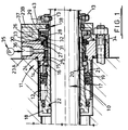
- the mechanical seal is fitted to, for example, a pump where the rotating shaft is indicated at 10 and the pump housing at 11.
- a shaft sleeve 12 surrounds and is keyed as indicated at 13 to rotate with the shaft 10.
- a main fluid seal is indicated at 14 and comprises a stationary seaiing ring 15 in face-to face contact with a rotating sealing ring 16.
- the rotating sealing ring 16 is urged into running contact with the stationary sealing ring 15 by an annular spring 17 abutting, at one end, a radial extension 18 of the shaft sleeve 12 and a spring carrier ring 19 at the other end.
- the spring carrier ring 19 is connected to a sealing ring carrier 20 which supports the rotating sealing ring 16.
- An O-ring seal 21 is disposed between the shaft sleeve 12, the spring carrier 19 and the sealing ring carrier 20.
- An O-ring seal 22 is also provided between the shaft 10 and the shaft sleeve 12 at the radial extension end of the latter.
- the mechanical seal housing is indicated at 23A, 23B and O-ring seals 24, 25 are respectively provided between same and the pump housing 11 and the stationary sealing ring 15.
- the mechanical seal also comprises a standby seal indicated at 26 which consists of a stationary sealing ring 27 and rotatable sealing ring 28, these seal rings being normally spaced apart, i.e. the standby seal 26 is normally open. As a result no wear takes place in the standby seal 26 during normal operation of the main seal 14.
- the rotary sealing ring 28 has associated with it a pumping ring 29 for rotation with it and the shaft sleeve 12.
- An O-ring seal 30 is provided between the seal housing 23A and the stationary sealing ring 27, and a piston ring 31 of, say, PTFE is provided between the latter and the shaft sleeve 12.
- This piston ring 31 serves to increase the sensitivity of the mechanical seal to leakage past the main fluid seal 14.
- O-ring seals 32, 33 are respectively provided between the rotating sealing ring 28 and the two parts 23A, 23B of the seal housing. These housing parts 23A, 23B are bolted together as indicated at 34.
- a pressure sensor 35 is fitted to a connection 36 in the seal housing 23A to permit monitoring of the pressure build-up between the main seal 14 and the standby secondary seal 26.
- the standby seal 26 will not become operative as long as liquid leakage from the main seal 14 is below a predetermined value. Such liquid leakage from the main seal 14 will pass the standby seal 26 unobstructed and will flow out of a drain connection 37 in the seal housing 23B.
- the lip seal/bush assembly 38 runs dry in all foreseeable conditions.
- the lip seal/bush arrangement 38 provides a complete closure to low level emissions from the main fluid seal 14 that do not actuate the secondary seal 26.
- the secondary seal 26 ensures that the lip seal/bush arrangement 38 is protected from high emissions which would result in a pressure build up between the secondary seal 26 and the lip seal/bush arrangement 38.
- the pumping ring 29 provides effective cooling to the secondary seal 26 when it is actuated by main seal leakage and also provides a low pressure area in front of the lip seal/bush arrangement 38. This low pressure area ensures that any leakage from the latter is inward and not outwardto atmosphere. This minimises the possible emissions from the mechanical seal.
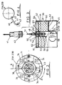
- an emission control cartridge 39 (see Fig. 3) according to this invention.
- This cartridge 39 is disposable and is connected by a quick fitting sealed coupling arrangement 40 to the drain connection 37 of the mechanical seal.
- the sealed coupling arrangement 40 comprises a hose 41 with at each end a coupling 42.
- One coupling 42 is connectible to a valve 43, normally spring-loaded to closed, at the mechanical seal drain connection 37, while the other coupling 42 is similarly connectible to a valve, normally spring loaded to closed, in the cartridge 39.
- the emission control cartridge 39 comprises a receptacle 44 of epoxy coated steel open at one end as indicated at 45 and centrally mounting the normally-closed valve indicated at 46.
- the valve 46 is carried by a bush 47 mounted in the cartridge casing 44, which bush 47 is traversed by an axial passage 48 having one or more lateral branch passages 49.
- the bush 47 mounts a coupling element 50 complementary to the coupling 42 and an axially-movable operating spindle 51 is supported in the axial passage 48.
- the bush 47 is plugged into an open end of a liquid container 52 and the spindle 51 extends therein and carries a valve element 53 supporting a fluor-silicon packing 54 adapted to abut the bush 47 to close the axial passage 48.
- a spring carrier 55 is connected to the bush 47 inside the container 52 and a coil spring 56 is supported at one end therein, the other end of the spring 56 abutting the valve element 53, 54 to urge the latter into the closed position.
- the lower end 57 of the container 52 is formed of glass or other suitable transparent material so that the content of the container 52 can readily be observed through viewing ports 58 in the housing 44.
- a float 59 is provided in the container 52, 57 to facilitate the aforesaid observation.
- An annular active carbon filter 60 surrounds the container 52 above its transparent lower end 57 and at each end is provided with a perforated filter end cap 61 with an internal layer 62 of wire mesh or textile.
- the filter 60 to 62 is spaced from the closed end 63 of the receptacle 44 to define a chamber 64 into which the or each lateral branch passage 49 opens.
- the normally-closed valve 43 in the mechanical seal is generally of the same construction as that in the emission control device but may be of any known construction provided it moves to open condition when its coupling 42 is secured thereto.
- valves 43 and 46 With the mechanical seal drain connection 37 connected to the emission control device by the sealed coupling arrangement 40, the valves 43 and 46 are open and any liquid leakage from the mechanical seal is collected in the container 52, 57. Any toxic vapour emission from this liquid passes along passages 48, 49 into the chamber 64 and thence to atmosphere through the carbon filter 60 which removes any toxicity from the vapour before it reaches the surrounding air.
- an operator can decide when the cartridge needs to be replaced. This decision can be facilitated by other means, for example a colouring medium in the container reactive to a predetermined value of toxicity of the liquid contained therein.
- the plant within which the pump is operating has sniffing equipment available to make checks at regular intervals to monitor the emission status of the emission control cartridge 39 so that regular monitoring of the emission status of the emission control cartridge 39 is effected.
- the vessel may be connected to the cartridge 39 without a normally-closed valve at the vessel end of the sealed coupling arrangement 40.
- mechanical seal is to be construed as meaning any apparatus or vessel from which liquid may leak which liquid is capable of emitting toxic or other undesirable substance vapours or from which there is direct emission of toxic or other undesirable substance vapours.
Landscapes
- Engineering & Computer Science (AREA)
- General Engineering & Computer Science (AREA)
- Mechanical Engineering (AREA)
- Chemical & Material Sciences (AREA)
- Analytical Chemistry (AREA)
- General Chemical & Material Sciences (AREA)
- Oil, Petroleum & Natural Gas (AREA)
- Chemical Kinetics & Catalysis (AREA)
- Mechanical Sealing (AREA)
- Vehicle Body Suspensions (AREA)
- Cookers (AREA)
- Selective Calling Equipment (AREA)
- Filtering Of Dispersed Particles In Gases (AREA)
- Separation Of Gases By Adsorption (AREA)
- Quick-Acting Or Multi-Walled Pipe Joints (AREA)
- Luminescent Compositions (AREA)
- Steering Control In Accordance With Driving Conditions (AREA)
- Filtration Of Liquid (AREA)
- Electrical Discharge Machining, Electrochemical Machining, And Combined Machining (AREA)
Claims (13)
- Vorrichtung zur Emissionskontrolle, welche zur Verbindung mit einer mechanischen Dichtung ausgeführt ist, wobei die Vorrichtung (39) zur Emissionskontrolle ein Gefäß (44) zur Aufnahme von aus der mechanischen Dichtung emittiertem Dampf umfaßt, und in der Vorrichtung (39) zur Emissionskontrolle ein Filter (60) zur Behandlung der Dampfemission untergebracht ist, wobei die Vorrichtung (39) zur Emissionskontrolle dadurch gekennzeichnet ist, daß in dem Gefäß (44) ein Behälter (52, 57) zur Aufnahme von dampftragendem Flüssigkeitsausfluß aus der mechanischen Dichtung untergebracht ist, welcher Behälter (52, 57) mit dem Filter (60) zwecks Durchgang von Dampfemission aus der gesammelten Flüssigkeit durch diesen Filter an die Umgebung in Verbindung steht, wobei der Filter (60) jegliche Toxizität aus der Dampfemission entfernt.
- Vorrichtung nach Anspruch 1, bei der der Filter (60) ein Aktivkohlefilter ist.
- Vorrichtung nach Anspruch 1 oder 2, bei der der Behälter (52, 57) zumindest teilweise aus Glas bzw. einem anderen durchsichtigen Material gebildet ist, um eine visuelle Überprüfung der Menge gesammelter Flüssigkeit zu ermöglichen.
- Vorrichtung nach Anspruch 3, bei der im Behälter (52, 57) zur Unterstützung einer derartigen Kontrolle ein Schwimmer (59) vorgesehen ist.
- Vorrichtung nach einem der Ansprüche 1 bis 4, bei der die Vorrichtung in Form einer Einwegpatrone (39) vorgesehen ist, die ein Ventil (46) umfaßt, welches so ausgeführt ist, daß es bei einer Abtrennung der Patrone (39) von der mechanischen Dichtung schließt, um eine Dampfemission aus der Patrone (39) zu verhindern.
- Vorrichtung nach Anspruch 5, bei der die Patrone (39) das Gefäß (44) umfaßt, welches zur Umgebung hin offen ist und in welchem der von dem Filter (60) umgebenen Behälter (52, 57) zur Sammlung von Flüssigkeit untergebracht ist, wobei das Ventil (46) zum Abschließen der zwischen dem Behälter (52, 57) und dem Filter (60) bestehenden Verbindung auf Verschluß hin vorgespannt wird.
- Vorrichtung nach Anspruch 5 oder 6, bei der das Ventil (46) einen Ventilschaft (51) aufweist, der durch eine abgedichtete Kupplungsanordnung (40) eines Schlauchs (41) mit Endkuppelstücken (42) betätigbar und so ausgeführt ist, daß er die Vorrichtung (39) zur Emissionskontrolle und die mechanische Dichtung in eine Wirkverbindung miteinander bringen kann.
- Vorrichtung nach einem der Ansprüche 1 bis 6, bei der der Filter (60) ringförmig und mit perforierten Endkappen (61) ausgeführt ist.
- Mechanische Dichtungsanordnung, welche eine mit einer Vorrichtung (39) zur Emissionskontrolle gemäß einem der Ansprüche 1 bis 8 in dichtender Verbindung stehende mechanische Dichtung umfaßt.
- Anordnung nach Anspruch 9, bei der die dichtende Verbindung einen Schlauch (41) umfaßt, der an jedem Ende ein Kuppelstück (42) für die jeweilge Verbindung mit der mechanischen Dichtung und der Vorrichtung (39) zur Emissionskontrolle aufweist.
- Anordnung nach Anspruch 10, bei der jedes jeweilige Kuppelstück (42) so ausgeführt ist, daß es ein normalerweise geschlossenes Ventil (43) an beispielsweise einer Abflußverbindung (37) der mechanischen Dichtung, und ein normalerweise geschlossenes Ventil (46) in der Vorrichtung (39) zur Emissionskontrolle in den offenen Zustand betätigen kann, wobei eine Abtrennung der Kuppelstücke (42) beide Ventile (43, 46) zum Schließen veranlaßt.
- Anordnung nach einem der Ansprüche 9 bis 11, in der die mechanische Dichtung eine normalerweise geschlossene Hauptdichtung (14), eine normalerweise offene Notdichtung (26) und einen Lippendichtung/Buchsen-Aufbau (38) umfaßt.
- Anordnung nach Anspruch 12, bei der die Abflußverbindung (37) sich zwischen der Notdichtung (26) und dem Lippendichtung/Buchsen-Aufbau (38) befindet.
Applications Claiming Priority (3)
| Application Number | Priority Date | Filing Date | Title |
|---|---|---|---|
| GB898924733A GB8924733D0 (en) | 1989-11-02 | 1989-11-02 | A mechanical seal |
| GB8924733 | 1989-11-02 | ||
| PCT/GB1990/001667 WO1991006793A1 (en) | 1989-11-02 | 1990-10-31 | Emission control device |
Publications (2)
| Publication Number | Publication Date |
|---|---|
| EP0500570A1 EP0500570A1 (de) | 1992-09-02 |
| EP0500570B1 true EP0500570B1 (de) | 1994-12-07 |
Family
ID=10665601
Family Applications (1)
| Application Number | Title | Priority Date | Filing Date |
|---|---|---|---|
| EP90915508A Expired - Lifetime EP0500570B1 (de) | 1989-11-02 | 1990-10-31 | Vorrichtung zur emissionskontrolle |
Country Status (9)
| Country | Link |
|---|---|
| EP (1) | EP0500570B1 (de) |
| JP (1) | JP3001629B2 (de) |
| AT (1) | ATE115248T1 (de) |
| AU (1) | AU644613B2 (de) |
| CA (1) | CA2072143C (de) |
| DE (1) | DE69014898D1 (de) |
| ES (1) | ES2067768T3 (de) |
| GB (2) | GB8924733D0 (de) |
| WO (1) | WO1991006793A1 (de) |
Cited By (1)
| Publication number | Priority date | Publication date | Assignee | Title |
|---|---|---|---|---|
| EP3022470B1 (de) * | 2013-07-17 | 2020-08-26 | IHC Holland IE B.V. | Wellendichtung und verfahren zum betrieb einer derartigen wellendichtung |
Families Citing this family (4)
| Publication number | Priority date | Publication date | Assignee | Title |
|---|---|---|---|---|
| EP0567527B1 (de) * | 1991-01-18 | 1998-04-22 | Flexibox Limited | Abgasentgiftung |
| CH686525A5 (de) * | 1992-07-02 | 1996-04-15 | Escher Wyss Ag | Turbomaschine . |
| FR2708699B1 (fr) * | 1993-08-06 | 1995-09-01 | Framatome Sa | Dispositif d'étanchéité pour arbre de machine tournante pressurisée. |
| CN102840125A (zh) * | 2011-06-21 | 2012-12-26 | 祁成 | 汽车冷却水泵的水封 |
Family Cites Families (3)
| Publication number | Priority date | Publication date | Assignee | Title |
|---|---|---|---|---|
| GB2204366B (en) * | 1986-01-31 | 1989-11-15 | Flexibox Ltd | Mechanical seals |
| US4722662A (en) * | 1986-06-17 | 1988-02-02 | Atlantic Richfield Company | Vapor emission control system for pumps |
| DE3801948C1 (en) * | 1988-01-23 | 1989-03-09 | Knecht Filterwerke Gmbh, 7000 Stuttgart, De | Activated carbon filter for fuel-tank ventilation |
-
1989
- 1989-11-02 GB GB898924733A patent/GB8924733D0/en active Pending
-
1990
- 1990-10-31 EP EP90915508A patent/EP0500570B1/de not_active Expired - Lifetime
- 1990-10-31 AU AU66013/90A patent/AU644613B2/en not_active Ceased
- 1990-10-31 CA CA002072143A patent/CA2072143C/en not_active Expired - Fee Related
- 1990-10-31 AT AT90915508T patent/ATE115248T1/de not_active IP Right Cessation
- 1990-10-31 WO PCT/GB1990/001667 patent/WO1991006793A1/en not_active Ceased
- 1990-10-31 DE DE69014898T patent/DE69014898D1/de not_active Expired - Lifetime
- 1990-10-31 ES ES90915508T patent/ES2067768T3/es not_active Expired - Lifetime
- 1990-10-31 JP JP2514461A patent/JP3001629B2/ja not_active Expired - Fee Related
-
1992
- 1992-04-29 GB GB9209246A patent/GB2254019B/en not_active Expired - Fee Related
Cited By (1)
| Publication number | Priority date | Publication date | Assignee | Title |
|---|---|---|---|---|
| EP3022470B1 (de) * | 2013-07-17 | 2020-08-26 | IHC Holland IE B.V. | Wellendichtung und verfahren zum betrieb einer derartigen wellendichtung |
Also Published As
| Publication number | Publication date |
|---|---|
| DE69014898D1 (de) | 1995-01-19 |
| JP3001629B2 (ja) | 2000-01-24 |
| JPH05501377A (ja) | 1993-03-18 |
| GB8924733D0 (en) | 1989-12-20 |
| GB9209246D0 (en) | 1992-07-01 |
| ATE115248T1 (de) | 1994-12-15 |
| EP0500570A1 (de) | 1992-09-02 |
| CA2072143C (en) | 2001-06-12 |
| WO1991006793A1 (en) | 1991-05-16 |
| ES2067768T3 (es) | 1995-04-01 |
| GB2254019B (en) | 1993-10-27 |
| AU644613B2 (en) | 1993-12-16 |
| CA2072143A1 (en) | 1991-05-03 |
| AU6601390A (en) | 1991-05-31 |
| GB2254019A (en) | 1992-09-30 |
Similar Documents
| Publication | Publication Date | Title |
|---|---|---|
| US5553867A (en) | Triple cartridge seal having one inboard and two concentric seals for chemical processing pump | |
| US4615812A (en) | Filter housing for closed fluid circulating system | |
| US3994503A (en) | Sealing assembly | |
| US4136886A (en) | Arrangement for cleaning a sealing ring on a shaft | |
| CZ284460B6 (cs) | Turbostroj s axiální plynovou třecí ucpávkou | |
| CN1054179C (zh) | 用于密封一根穿过壳体的轴所用套管的密封装置及其工作方法 | |
| CA2075131C (en) | Pump including secondary containment with alarm system | |
| EP0500570B1 (de) | Vorrichtung zur emissionskontrolle | |
| US4722662A (en) | Vapor emission control system for pumps | |
| US3749411A (en) | Shaft sealing system | |
| US3589737A (en) | Mechanical seal for a vertical rotating | |
| JP2766875B2 (ja) | 軸封システム装置 | |
| JP7069217B2 (ja) | 危険物質のためのプロセスユニット | |
| US4537385A (en) | Low emission valve | |
| CA1141408A (en) | Seal | |
| US20110148048A1 (en) | Sealing arrangement | |
| CN207893242U (zh) | 一种用于阀门的内漏在线监测装置 | |
| US5277545A (en) | Vapor emission control | |
| US5893703A (en) | Pump shaft sealing system | |
| US4877371A (en) | Pump | |
| JP3232493B2 (ja) | 軸封装置 | |
| CA2248202A1 (en) | Emission containment and alignment apparatus and method for fluid systems | |
| US5337859A (en) | Process gas compressor train Fugitive Emissions Recovery system | |
| US2069963A (en) | Rotary strainer | |
| JPH09177991A (ja) | 回転機の軸封装置 |
Legal Events
| Date | Code | Title | Description |
|---|---|---|---|
| PUAI | Public reference made under article 153(3) epc to a published international application that has entered the european phase |
Free format text: ORIGINAL CODE: 0009012 |
|
| 17P | Request for examination filed |
Effective date: 19920522 |
|
| AK | Designated contracting states |
Kind code of ref document: A1 Designated state(s): AT BE CH DE DK ES FR GB GR IT LI LU NL SE |
|
| RBV | Designated contracting states (corrected) |
Designated state(s): AT BE CH DE DK ES FR GR IT LI LU NL SE |
|
| 17Q | First examination report despatched |
Effective date: 19940120 |
|
| GRAA | (expected) grant |
Free format text: ORIGINAL CODE: 0009210 |
|
| AK | Designated contracting states |
Kind code of ref document: B1 Designated state(s): AT BE CH DE DK ES FR GR IT LI LU NL SE |
|
| PG25 | Lapsed in a contracting state [announced via postgrant information from national office to epo] |
Ref country code: LI Effective date: 19941207 Ref country code: GR Free format text: LAPSE BECAUSE OF FAILURE TO SUBMIT A TRANSLATION OF THE DESCRIPTION OR TO PAY THE FEE WITHIN THE PRESCRIBED TIME-LIMIT Effective date: 19941207 Ref country code: DK Effective date: 19941207 Ref country code: CH Effective date: 19941207 Ref country code: AT Effective date: 19941207 |
|
| REF | Corresponds to: |
Ref document number: 115248 Country of ref document: AT Date of ref document: 19941215 Kind code of ref document: T |
|
| REF | Corresponds to: |
Ref document number: 69014898 Country of ref document: DE Date of ref document: 19950119 |
|
| ITF | It: translation for a ep patent filed | ||
| PG25 | Lapsed in a contracting state [announced via postgrant information from national office to epo] |
Ref country code: SE Effective date: 19950307 |
|
| PG25 | Lapsed in a contracting state [announced via postgrant information from national office to epo] |
Ref country code: DE Effective date: 19950308 |
|
| REG | Reference to a national code |
Ref country code: CH Ref legal event code: PL |
|
| ET | Fr: translation filed | ||
| REG | Reference to a national code |
Ref country code: ES Ref legal event code: FG2A Ref document number: 2067768 Country of ref document: ES Kind code of ref document: T3 |
|
| PLBE | No opposition filed within time limit |
Free format text: ORIGINAL CODE: 0009261 |
|
| STAA | Information on the status of an ep patent application or granted ep patent |
Free format text: STATUS: NO OPPOSITION FILED WITHIN TIME LIMIT |
|
| PG25 | Lapsed in a contracting state [announced via postgrant information from national office to epo] |
Ref country code: LU Free format text: LAPSE BECAUSE OF NON-PAYMENT OF DUE FEES Effective date: 19951031 |
|
| 26N | No opposition filed | ||
| PG25 | Lapsed in a contracting state [announced via postgrant information from national office to epo] |
Ref country code: NL Free format text: LAPSE BECAUSE OF NON-PAYMENT OF DUE FEES Effective date: 19951130 |
|
| PGFP | Annual fee paid to national office [announced via postgrant information from national office to epo] |
Ref country code: FR Payment date: 20021008 Year of fee payment: 13 |
|
| PGFP | Annual fee paid to national office [announced via postgrant information from national office to epo] |
Ref country code: NL Payment date: 20021031 Year of fee payment: 13 Ref country code: ES Payment date: 20021031 Year of fee payment: 13 |
|
| PGFP | Annual fee paid to national office [announced via postgrant information from national office to epo] |
Ref country code: BE Payment date: 20021219 Year of fee payment: 13 |
|
| PG25 | Lapsed in a contracting state [announced via postgrant information from national office to epo] |
Ref country code: BE Free format text: LAPSE BECAUSE OF NON-PAYMENT OF DUE FEES Effective date: 20031031 |
|
| PG25 | Lapsed in a contracting state [announced via postgrant information from national office to epo] |
Ref country code: ES Free format text: LAPSE BECAUSE OF NON-PAYMENT OF DUE FEES Effective date: 20031103 |
|
| BERE | Be: lapsed |
Owner name: *FLEXIBOX LTD Effective date: 20031031 |
|
| PG25 | Lapsed in a contracting state [announced via postgrant information from national office to epo] |
Ref country code: FR Free format text: LAPSE BECAUSE OF NON-PAYMENT OF DUE FEES Effective date: 20040630 |
|
| NLV4 | Nl: lapsed or anulled due to non-payment of the annual fee |
Effective date: 20040501 |
|
| REG | Reference to a national code |
Ref country code: FR Ref legal event code: ST |
|
| REG | Reference to a national code |
Ref country code: ES Ref legal event code: FD2A Effective date: 20031103 |
|
| PG25 | Lapsed in a contracting state [announced via postgrant information from national office to epo] |
Ref country code: IT Free format text: LAPSE BECAUSE OF NON-PAYMENT OF DUE FEES Effective date: 20051031 |