EP0499895B1 - Dispositif de formage d'éléments de construction en forme de courbe - Google Patents
Dispositif de formage d'éléments de construction en forme de courbe Download PDFInfo
- Publication number
- EP0499895B1 EP0499895B1 EP92101995A EP92101995A EP0499895B1 EP 0499895 B1 EP0499895 B1 EP 0499895B1 EP 92101995 A EP92101995 A EP 92101995A EP 92101995 A EP92101995 A EP 92101995A EP 0499895 B1 EP0499895 B1 EP 0499895B1
- Authority
- EP
- European Patent Office
- Prior art keywords
- guides
- clamping
- carriage
- curved
- clamping elements
- Prior art date
- Legal status (The legal status is an assumption and is not a legal conclusion. Google has not performed a legal analysis and makes no representation as to the accuracy of the status listed.)
- Expired - Lifetime
Links
Images


Classifications
-
- B—PERFORMING OPERATIONS; TRANSPORTING
- B27—WORKING OR PRESERVING WOOD OR SIMILAR MATERIAL; NAILING OR STAPLING MACHINES IN GENERAL
- B27D—WORKING VENEER OR PLYWOOD
- B27D1/00—Joining wood veneer with any material; Forming articles thereby; Preparatory processing of surfaces to be joined, e.g. scoring
- B27D1/04—Joining wood veneer with any material; Forming articles thereby; Preparatory processing of surfaces to be joined, e.g. scoring to produce plywood or articles made therefrom; Plywood sheets
- B27D1/08—Manufacture of shaped articles; Presses specially designed therefor
- B27D1/083—Presses specially designed for making the manufacture of shaped plywood articles
-
- B—PERFORMING OPERATIONS; TRANSPORTING
- B27—WORKING OR PRESERVING WOOD OR SIMILAR MATERIAL; NAILING OR STAPLING MACHINES IN GENERAL
- B27H—BENDING WOOD OR SIMILAR MATERIAL; COOPERAGE; MAKING WHEELS FROM WOOD OR SIMILAR MATERIAL
- B27H1/00—Bending wood stock, e.g. boards
Definitions
- the invention relates to a device for shaping curved components, in particular glulam beams, curved beams or the like, according to the preamble of patent claim 1.
- a bending device of the type mentioned comprises for the generation of the bending shape of the part to be bent a fixed part, which is preferably cylindrical or at least has a curved surface on the opposite sides.
- the counterpart to this is a complementary component which can be moved in a sled shape, the actual bending shape of the part to be bent being determined by the space between the fixed and the movable molded part of the bending device.
- These separate shaped and counter-shaped parts of the bending device not only have to be manufactured separately, but they also have to be set to the desired positions in the bending process to be carried out in each case. This adjustment work is time-consuming, and for the production of the shaped and counter-shaped parts which determine the bending shape, a considerable amount of material and time is additionally required.
- angle brackets which are anchored in a concrete bed, are arranged in such a way that they have an arrangement, for example comprises a plurality of angular brackets which are arranged in the manner of a template which is curved in accordance with the component to be produced. Aligning and arranging the brackets to form such a template is time consuming and the work required to do this must be done by hand.
- the invention has for its object to provide a device for molding curved components of the generic type, which allows a simplified manufacture of curved components with a selectable curvature and any length.
- this object is achieved in a device for shaping curved components, in particular glulam beams, curved beams or the like, which has the features of the preamble of patent claim 1, in conjunction with the features of its characteristics.
- any curved components such as curved beam parts designed as glued laminated beams
- the slides of the tensioning devices which serve as the base body can be moved to the desired locations while achieving the respectively desired arc shape of the component to be produced and the rotary tables mounted thereon with the at least two adjustable clamping elements, when the component is inserted and bent, are automatically aligned in the required angular position, the clamping elements being able to be opened and closed in any position of the slide, so that, if necessary can exert different pressing pressures on the component to be manufactured.
- This device allows the production of components with any curvature in an almost universal manner, without time-consuming and complicated alignment work for the respective clamping devices.
- the number of clamping devices used in the device for shaping curved components according to the invention can also be adapted to the desired application and, thanks to the modular design, can be expanded almost freely. This also ensures that the lengths of the curved components to be produced can be freely selected.
- the device according to the invention is not only in the field of the production of glued wood and, for example, for the shaping of glulam beams in the production of components for residential building, such as door frames, lintels, dormer windows, rafters etc. of formwork for concrete workers, of components for conservatories, pavilions, Pergolas, car parking spaces, playgrounds, etc. are particularly suitable, but this device can also be used to achieve shapes with other materials with similar elasticity modules, as is the case, for example, when creating welded structures from steel components.
- the guides for the movable carriages are preferably arranged parallel to one another, and they are expediently provided in this arrangement on a base frame, so that the clamping devices can be moved independently of one another into the respectively desired position.
- the device comprises a common drive device for moving the slides of the tensioning devices, for which purpose motors, chain drives and the like can be provided on the base frame of the device, for example, so that the work for the respective positioning of the slides of the tensioning devices can also be carried out easily and quickly Let untrained and inexperienced personnel do it.
- a common drive device for moving the slides of the tensioning devices for which purpose motors, chain drives and the like can be provided on the base frame of the device, for example, so that the work for the respective positioning of the slides of the tensioning devices can also be carried out easily and quickly Let untrained and inexperienced personnel do it.
- Slideways or roller guides or combinations thereof can be used to guide the slide of each tensioning device, the respective type of guidance naturally also being dependent on the required manufacturing accuracy of the components to be manufactured and their size and / or length. It has proven to be particularly preferred to make the carriages of the tensioning devices movable on rollers along the guides, which are expediently designed as rail guides.
- the tensioning elements of the respective tensioning device which are adjustable symmetrically to the axis of rotation, are preferably formed by tensioning rollers, so that when the component to be manufactured is deformed, when the tensioning devices arranged in parallel are moved, the component can roll on these tensioning rollers and a line contact of the tensioning devices and the one to be manufactured Part to avoid any visible bend marks on the surface of the part being manufactured.
- the adjustment device for the tensioning elements can also be driven by a motor with the aid of an electric, hydraulic, pneumatic drive
- the clamping forces required in each case can be varied and coordinated in an individual manner.
- a basic embodiment of a device according to the The invention includes, for example, seven adjustable clamping devices of the type mentioned above, and the most common lengths of the components to be bent can be processed with such a device.
- the number of clamping devices of the device can be expanded as desired.
- a manual control or a computer-aided control is preferably provided for controlling the device.
- the manual control allows an individual input and specification of the travel paths and manipulated variables required for the production of the components, while a computer-aided control in particular allows a fully automatic operation of the device according to the invention with the lowest possible personnel expenditure.
- the computer-aided control can also be expediently designed in such a way that it can process information and data, such as CAD data, obtained directly during the design of the components to be manufactured and can determine the required settings from this in order to adjust the respective clamping devices of the device and its parts position as desired. In this way, on-line operation is possible, for example, with a central computer for design and manufacture.
- information and data such as CAD data
- the device has a modular structure, so that one can achieve almost universal flexibility for shaping the most varied configurations of the components.
- the tensioning devices can be moved independently of one another. Depending on the respective application, the tensioning devices can also be moved in a predetermined sequence and coupled to one another, if necessary.
- the tensioning devices are preferably arranged in a common plane, which is formed by the guides provided in parallel for moving the carriage of the tensioning device.
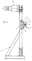
- a device for shaping and pressing curved components is explained with reference to FIGS. 1 and 2 using an example for producing a curved beam from a board layer support.
- the device is designated there overall by 1.
- eight guides 3 for a total of seven clamping devices 4 are attached to a base frame 2 of the device 1.
- the guides 3 are formed by rails 5 provided in parallel, lengthways which the clamping devices 4 can be moved independently of one another.
- Each tensioning device 4 has a base body which can be moved along the guides 3 and which is designed as a slide 6 which can be moved on the rails 5 serving as guides 3 by means of rollers 7.
- This carriage 6 has a central axis 8.
- a rotary table or turntable 9 is rotatably mounted about this central axis 8, ie it is mounted centrally on the carriage 6 about a vertical or vertical axis in FIG.
- On the turntable 9 are provided symmetrically to the axis of rotation 8 and diametrically opposite clamping elements 10, which are provided on the turntable 9 adjustable by means of a displacement movement.
- the tensioning elements 10 can be moved toward or away from one another to change or distance the same between them in order to open or close the tensioning device.
- the tensioning elements 10 are formed by two tensioning rollers 12 in a diametrically opposite arrangement.
- a drive device 13 which in the example shown is formed by a motor-driven chain drive, the carriages 6 are moved individually along the guides 3.
- other drive devices than the drive device 13 shown can also be used to move the carriage 6.
- the device 1 explained above essentially has the mode of operation described in more detail below.
- the carriages 6 are supported the drive device 13 to a desired control, not shown, move to the desired positions.
- the clamping elements 10 of the clamping devices 4 are still at least partially opened until the slides 6 assume their intended position.
- the beam 14 can then roll on the tensioning rollers 12 until the desired curved shape of the beam 14, shown for example in FIG. 1, is obtained.
- the respective rotary tables 9 automatically align themselves with the component to be bent, such as the beam 14, with regard to the angular position.
- the slide 6 can be locked in the intended end position on the guides 3 and fixed immovably.
- the centrally arranged adjusting device 11 which can be formed, for example, by a chain sprocket 15
- the tensioning elements 10 are then moved relative to one another with respect to the central axis 8 in such a way that the tensioning elements 10 with a predetermined pressing force on the beam part 14 in the curved shape taking into account the thickness of the beam part 14 abut.
- the clamping devices 4 can be opened by adjusting the clamping elements 10 in the opening direction, the clamping elements 10 being moved in the direction away from one another, so that the bent beam part 14 is removed from the device 1 can be.
- the number of seven tensioning devices 4 is adjusted to a length of the bar part 14 with an average size. Due to the modular structure with the respective clamping devices 4 and these associated guides 3, the device 1 can of course be expanded as desired. Flexible adaptation is also possible in a structurally simple manner, taking into account differently manufactured components with different curvatures at any time.
- the control used for the device 1 can be selected.
- This control can be a manual control or an automatic control, such as a computer-based control.
- Such a computer-aided control of the device 1 can even allow direct input and processing of information and data created during the construction, for example if the so-called computer-aided design (CAD) method is used in the construction. In this way, data obtained when creating individual part drawings, for example from a structural engineer or architect, can be used directly as input data for controlling the device 1.
- CAD computer-aided design
- the device 1 for shaping and optionally pressing curved components enables rapid, inexpensive production of components which are curved in any desired manner from different materials.
- the device 1 is easy to use and has a stable construction comprising several individual module components. The considerable time saved in the production of curved components using the device 1 represents a major advantage of the device 1.
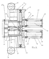
- rollers 7 of the carriage 6 serving as the base body of the tensioning device 4 each run in a parallel pair of rails 5, which form the longitudinal guides 3 for the carriage 6.
- four rollers 7 are provided on the respective carriage 6, for example.
- the rotary table 9 is rotatably mounted on the carriage 6 about the central axis 8. In a diametrically opposed arrangement to the central axis 8, two tensioning rollers 12 are symmetrically displaceable along the longitudinal guides on the turntable 9 stored.
- the sprocket 15 is provided with an adjusting spindle part 16 on its shaft 17 and a centrally arranged gear transmission device 18, which is accommodated in the turntable 9, so that when the sprocket 15 rotates via the gear transmission device 18, the tensioning rollers 12 have an adjustment movement along their axis Guided tours on the turntable 9 is given.
- the tensioning rollers 12 can be moved towards or away from one another in order to achieve the desired clamping of the component to be manufactured.
- the detail shown and explained with reference to FIGS. 3 to 5 represents, for example, a module of the device, which is denoted overall by 1, for forming curved components 14.
- the tensioning rollers 12 can be rotated about their own axis 20, so that the part to be produced is produced Component can roll on the tension rollers 12.
- a corresponding actuator can drive the respective tensioning rollers 12 via the gear transmission device 18 in order to carry out a movement along these guides.
- the respective clamping devices 4 are designed such that they have sufficient inherent rigidity in order to be able to achieve the desired accuracy in the components 14 to be produced. Overall, the device 1 is designed to be robust and resistant.
- the invention is not limited to the details of the preferred embodiment of the device 1 shown above, but numerous changes and modifications are possible, which the person skilled in the art will make if necessary, without departing from the inventive concept.
- Essential to the design of the device 1 according to the invention is its modular structure using separate clamping devices, which have a rotary table 9 mounted centrally on a slide 6, which carries the clamping elements 10, and which automatically adjusts itself to the curvature of the component 14 to be adapted.
- the controls, the drive devices 13 and the adjusting device 11 can be selected depending on the design effort for the device 1 in the respectively desired embodiment.
Landscapes
- Life Sciences & Earth Sciences (AREA)
- Engineering & Computer Science (AREA)
- Mechanical Engineering (AREA)
- Wood Science & Technology (AREA)
- Forests & Forestry (AREA)
- Manufacturing & Machinery (AREA)
- Bending Of Plates, Rods, And Pipes (AREA)
- Fuel-Injection Apparatus (AREA)
- Surgical Instruments (AREA)
Claims (15)
- Dispositif de mise en forme d'éléments de constructions courbés en particulier de poutres lamellées collées, de poutres incurvées, ou etc ., avec au moins deux éléments de serrage mobiles sur des platines tournantes (9), qui chacun présente des coulisseaux (6), comme organes de base, déplaçables le long de glissières de guidage (3), caractérisé en ce que- la platine tournante (9) est montée rotative sur l'axe central (8) du coulisseau (6),- au moins deux éléments de serrage (10) réglables symétriquement sont diamétralement opposés selon un diamètre, symétriques par rapport à l'axe central (8) du coulisseau (6) sur la platine (9), et- un dispositif de réglage (11) disposé au centre pour changer l'écartement entre les éléments de serrage (10) et pour ouvrir ou fermer le dispositif respectif de serrage (4).
- Dispositif selon la revendication 1, caractérisé en ce que les glissières de guidage (3) pour les coulisseaux déplaçables (6) sont disposées parallèlement l'une à l'autre.
- Dispositif selon la revendication 2, caractérisé en ce que les glissières de guidage (3) disposées parallèlement l'une à l'autre sont prévues sur un bâti de base (2).
- Dispositif selon l'une des revendications 1 à 3, caractérisé en ce qu'un dispositif moteur commun (13) est prévu pour déplacer les coulisseaux (6).
- Dispositif selon l'une des revendications 1 à 4, caractérisé en ce que le coulisseau (6) est monté mobile en glissement sur la glissière de guidage (3).
- Dispositif selon l'une des revendications 1 à 4, caractérisé en ce que le coulisseau (6) est déplaçable le long de la glissière de guidage (3) sur des rouleaux (7).
- Dispositif selon l'une des revendications 1 à 6, caractérisé en ce que les éléments de serrage (10) sont constitués de galets de tension (12).
- Dispositif selon l'une des revendications 1 à 7, caractérisé en ce que le dispositif de réglage (11) pour les éléments de serrage (10) présente un pignon à roue dentée (15) avec un dispositif de transmission par roues dentées (18) pour la disposition symétrique des éléments de serrage (10; 12) par rapport à l'axe de rotation (8) de la platine tournante (9) ou à l'axe (8) du coulisseau (6).
- Dispositif selon l'une des revendications précédentes, caractérisé en ce que le dispositif (1) présente une disposition comportant sept dispositifs de serrage (4) réglables.
- Dispositif selon l'une des revendications précédentes, caractérise en ce qu'une commande manuelle ou une commande automatisée est prévue pour piloter le dispositif (1).
- Dispositif selon la revendication 10, caractérisé en ce que la commande automatisée met en oeuvre des données CAD fournies.
- Dispositif suivant l'une des revendications précédentes, caractérisé an ce que le dispositif (1) a une construction modulaire.
- Dispositif suivant l'une des revendications précédentes, caractérisé en ce qu'au moyen du dispositif, on peut installer des éléments de construction coudés en acier pour des constructions soudées.
- Dispositif suivant l'une des revendications 1 à 13, caractérisé en ce qu'on peut déplacer indépendamment les uns des autres les dispositifs de serrage (4).
- Dispositif suivant l'une des revendications 1 à 14, caractérisé en ce qu'on peut disposer les dispositifs de serrage (4) dons un même plan.
Applications Claiming Priority (2)
| Application Number | Priority Date | Filing Date | Title |
|---|---|---|---|
| DE4103893A DE4103893C1 (fr) | 1991-02-08 | 1991-02-08 | |
| DE4103893 | 1991-02-08 |
Publications (2)
| Publication Number | Publication Date |
|---|---|
| EP0499895A1 EP0499895A1 (fr) | 1992-08-26 |
| EP0499895B1 true EP0499895B1 (fr) | 1995-05-10 |
Family
ID=6424682
Family Applications (1)
| Application Number | Title | Priority Date | Filing Date |
|---|---|---|---|
| EP92101995A Expired - Lifetime EP0499895B1 (fr) | 1991-02-08 | 1992-02-06 | Dispositif de formage d'éléments de construction en forme de courbe |
Country Status (4)
| Country | Link |
|---|---|
| US (1) | US5199475A (fr) |
| EP (1) | EP0499895B1 (fr) |
| AT (1) | ATE122277T1 (fr) |
| DE (2) | DE4103893C1 (fr) |
Families Citing this family (11)
| Publication number | Priority date | Publication date | Assignee | Title |
|---|---|---|---|---|
| DE4307928C2 (de) * | 1993-03-12 | 1996-03-21 | Koeder Ingb Sondermaschbau | Vorrichtung zum Formen von gekrümmten Bauteilen |
| FR2722130B1 (fr) * | 1994-07-06 | 1996-09-20 | Gauthier Paul Sa | Plan modulaire d'assemblage pour la mise en forme de poutres courbes en lamelle-colle |
| US5558143A (en) * | 1994-10-13 | 1996-09-24 | The Longaberger Company | Variable radius bowing press |
| GB9800447D0 (en) * | 1998-01-10 | 1998-03-04 | Parkhill International Limited | Curtain making apparatus |
| US6330894B1 (en) * | 2000-09-14 | 2001-12-18 | Donald G. Austin | Wood bending jig |
| US7886785B2 (en) * | 2007-02-15 | 2011-02-15 | Julius Young | Machine and method for installing curved hardwood flooring |
| US8113266B2 (en) * | 2007-07-26 | 2012-02-14 | Smoke Guard, Inc. | Barrier systems and associated methods, including vapor and/or fire barrier systems |
| IT1401553B1 (it) | 2010-07-22 | 2013-07-26 | Scm Group Spa | Macchina per assemblare corpi lamellari |
| EP2758236A4 (fr) * | 2011-09-19 | 2015-06-03 | Machinery Llc Sd | Appareil de formation de matériau |
| CN104325526A (zh) * | 2014-11-25 | 2015-02-04 | 常熟市东方新型包装材料有限公司 | 木材热弯设备 |
| CN106270226B (zh) * | 2016-08-30 | 2018-05-15 | 长春工业大学 | 汽车轮罩滚压包边机器人 |
Family Cites Families (9)
| Publication number | Priority date | Publication date | Assignee | Title |
|---|---|---|---|---|
| DE180404C (fr) * | ||||
| US927925A (en) * | 1909-04-06 | 1909-07-13 | Perforated Pad Company | Bridle-rosette. |
| US1561613A (en) * | 1924-02-15 | 1925-11-17 | John L Mckeown | Bending and clamping frame |
| US2331927A (en) * | 1941-08-11 | 1943-10-19 | Kraft Cheese Company | Package sealing apparatus |
| US2399348A (en) * | 1943-03-01 | 1946-04-30 | Hobbs Frank | Bending mechanism |
| US3172453A (en) * | 1962-12-31 | 1965-03-09 | Todd Shipyards Corp | Position control for multiple tools |
| EP0211810A1 (fr) * | 1985-06-10 | 1987-02-25 | Remo Angelucci | Plateau de formage de structures laminées courbes |
| US4711281A (en) * | 1986-03-05 | 1987-12-08 | Michael Kessel | Curved wood bending machine |
| DE3641270A1 (de) * | 1986-12-03 | 1988-06-16 | Helmut Klingler | Verfahren und geraete zur herstellung von holzlaminatformen mit eng-radigen winkelbogen sowie bogenformen mittels herstellung der biegefaehigkeit, biegen und verleimen von holzlamellen |
-
1991
- 1991-02-08 DE DE4103893A patent/DE4103893C1/de not_active Expired - Fee Related
-
1992
- 1992-02-06 AT AT92101995T patent/ATE122277T1/de not_active IP Right Cessation
- 1992-02-06 DE DE59202107T patent/DE59202107D1/de not_active Expired - Fee Related
- 1992-02-06 EP EP92101995A patent/EP0499895B1/fr not_active Expired - Lifetime
- 1992-02-10 US US07/833,043 patent/US5199475A/en not_active Expired - Fee Related
Also Published As
| Publication number | Publication date |
|---|---|
| ATE122277T1 (de) | 1995-05-15 |
| EP0499895A1 (fr) | 1992-08-26 |
| DE59202107D1 (de) | 1995-06-14 |
| US5199475A (en) | 1993-04-06 |
| DE4103893C1 (fr) | 1992-05-07 |
Similar Documents
| Publication | Publication Date | Title |
|---|---|---|
| DE2800902A1 (de) | Schneidmaschine zum schneiden einer mehrfach gekruemmten flaeche an einem werkstueck | |
| EP0499895B1 (fr) | Dispositif de formage d'éléments de construction en forme de courbe | |
| WO2006024058A1 (fr) | Installation d'usinage, en particulier installation de delignage et de decoupage de panneaux | |
| EP0164063B1 (fr) | Machine-outil pour l'usinage des planches | |
| DE68903494T2 (de) | Maschine zum schneiden von granitblock- oder steinmaterialien in platten. | |
| EP1579965B1 (fr) | Appareil pour découper une partie frontale d'un profil constituant une forme négative d'une ramification de conduite | |
| DE3009615C2 (fr) | ||
| EP0997260A2 (fr) | Dispositif pour recouvrir des pièces | |
| DE102007057407A1 (de) | Maschine zum Fräsen des Längsprofils der Schäfte von Schlüsseln für Zylinderschlösser und Verfahren zur Bearbeitung von Schäften an Schlüsseln für Zylinderschlösser durch Fräsen | |
| EP0222728B1 (fr) | Appareil de production de poutres prismatiques ou pyramidales | |
| EP0330970A2 (fr) | Dispositif pour le positionnement d'éléments de cadre courbes et pour le fraisage de rainures trapézoidales dans ces éléments de cadre | |
| DE3637713A1 (de) | Positioniereinrichtung fuer platten- oder stabfoermige werkstuecke in bearbeitungsmaschinen | |
| DE4411255A1 (de) | Sägemaschine für Gehrungs- und Schifterschnitte I | |
| EP0787560B1 (fr) | Dispositif d'usinage des barres, des profilés et similaire | |
| DE3928850A1 (de) | Vorrichtung zum stapeln und entstapeln von tafelfoermigem gut | |
| WO2015135909A1 (fr) | Scie à câble et utilisation d'une scie à câble | |
| DE3639778C2 (de) | Vorrichtung zum Bearbeiten von Kanten von plattenförmigen Werkstücken | |
| EP0813941B2 (fr) | Machine-outil pour l'usinage de pièces allongées | |
| DE19621667A1 (de) | Vorrichtung zum Zuschneiden von Rahmenteilen | |
| DE4307928C2 (de) | Vorrichtung zum Formen von gekrümmten Bauteilen | |
| DE102004050867B4 (de) | Styroporschneider | |
| EP0607913B1 (fr) | Dispositif d'alimentation des pièces à usiner dans une machine automatique pour le travail du bois | |
| DE3420075A1 (de) | Vorrichtung zum transfer von werkstuecken zwischen mehreren stationen einer presseinrichtung | |
| EP1644141B1 (fr) | Dispositif pour fabriquer un materiau d'etirage a surface plane | |
| EP1048374A2 (fr) | Dispositif d'enroulement de ressorts, en particulier pour machines d'enroulement de ressorts |
Legal Events
| Date | Code | Title | Description |
|---|---|---|---|
| PUAI | Public reference made under article 153(3) epc to a published international application that has entered the european phase |
Free format text: ORIGINAL CODE: 0009012 |
|
| AK | Designated contracting states |
Kind code of ref document: A1 Designated state(s): AT CH DE DK ES FR GB GR IT LI NL PT SE |
|
| 17P | Request for examination filed |
Effective date: 19930223 |
|
| 17Q | First examination report despatched |
Effective date: 19940520 |
|
| GRAA | (expected) grant |
Free format text: ORIGINAL CODE: 0009210 |
|
| AK | Designated contracting states |
Kind code of ref document: B1 Designated state(s): AT CH DE DK ES FR GB GR IT LI NL PT SE |
|
| PG25 | Lapsed in a contracting state [announced via postgrant information from national office to epo] |
Ref country code: IT Free format text: LAPSE BECAUSE OF FAILURE TO SUBMIT A TRANSLATION OF THE DESCRIPTION OR TO PAY THE FEE WITHIN THE PRESCRIBED TIME-LIMIT;WARNING: LAPSES OF ITALIAN PATENTS WITH EFFECTIVE DATE BEFORE 2007 MAY HAVE OCCURRED AT ANY TIME BEFORE 2007. THE CORRECT EFFECTIVE DATE MAY BE DIFFERENT FROM THE ONE RECORDED. Effective date: 19950510 Ref country code: GR Free format text: LAPSE BECAUSE OF FAILURE TO SUBMIT A TRANSLATION OF THE DESCRIPTION OR TO PAY THE FEE WITHIN THE PRESCRIBED TIME-LIMIT Effective date: 19950510 Ref country code: FR Effective date: 19950510 Ref country code: ES Free format text: THE PATENT HAS BEEN ANNULLED BY A DECISION OF A NATIONAL AUTHORITY Effective date: 19950510 Ref country code: DK Effective date: 19950510 Ref country code: NL Free format text: LAPSE BECAUSE OF FAILURE TO SUBMIT A TRANSLATION OF THE DESCRIPTION OR TO PAY THE FEE WITHIN THE PRESCRIBED TIME-LIMIT Effective date: 19950510 Ref country code: GB Effective date: 19950510 |
|
| REF | Corresponds to: |
Ref document number: 122277 Country of ref document: AT Date of ref document: 19950515 Kind code of ref document: T |
|
| REF | Corresponds to: |
Ref document number: 59202107 Country of ref document: DE Date of ref document: 19950614 |
|
| PG25 | Lapsed in a contracting state [announced via postgrant information from national office to epo] |
Ref country code: SE Effective date: 19950810 Ref country code: PT Effective date: 19950810 |
|
| EN | Fr: translation not filed | ||
| NLV1 | Nl: lapsed or annulled due to failure to fulfill the requirements of art. 29p and 29m of the patents act | ||
| GBV | Gb: ep patent (uk) treated as always having been void in accordance with gb section 77(7)/1977 [no translation filed] |
Effective date: 19950510 |
|
| PG25 | Lapsed in a contracting state [announced via postgrant information from national office to epo] |
Ref country code: CH Effective date: 19960229 Ref country code: LI Effective date: 19960229 |
|
| PLBE | No opposition filed within time limit |
Free format text: ORIGINAL CODE: 0009261 |
|
| STAA | Information on the status of an ep patent application or granted ep patent |
Free format text: STATUS: NO OPPOSITION FILED WITHIN TIME LIMIT |
|
| 26N | No opposition filed | ||
| REG | Reference to a national code |
Ref country code: CH Ref legal event code: PL |
|
| PGFP | Annual fee paid to national office [announced via postgrant information from national office to epo] |
Ref country code: AT Payment date: 20020220 Year of fee payment: 11 |
|
| PGFP | Annual fee paid to national office [announced via postgrant information from national office to epo] |
Ref country code: DE Payment date: 20020226 Year of fee payment: 11 |
|
| PG25 | Lapsed in a contracting state [announced via postgrant information from national office to epo] |
Ref country code: AT Free format text: LAPSE BECAUSE OF NON-PAYMENT OF DUE FEES Effective date: 20030206 |
|
| PG25 | Lapsed in a contracting state [announced via postgrant information from national office to epo] |
Ref country code: DE Free format text: LAPSE BECAUSE OF NON-PAYMENT OF DUE FEES Effective date: 20030902 |