EP0499523B1 - Düse mit angehobenem stromabwärts liegendem Absatz zur Beschichtung eines Glasbandes durch Pyrolyse eines Gasgemisches - Google Patents
Düse mit angehobenem stromabwärts liegendem Absatz zur Beschichtung eines Glasbandes durch Pyrolyse eines Gasgemisches Download PDFInfo
- Publication number
- EP0499523B1 EP0499523B1 EP19920400343 EP92400343A EP0499523B1 EP 0499523 B1 EP0499523 B1 EP 0499523B1 EP 19920400343 EP19920400343 EP 19920400343 EP 92400343 A EP92400343 A EP 92400343A EP 0499523 B1 EP0499523 B1 EP 0499523B1
- Authority
- EP
- European Patent Office
- Prior art keywords
- heel
- upstream
- downstream
- glass
- nozzle
- Prior art date
- Legal status (The legal status is an assumption and is not a legal conclusion. Google has not performed a legal analysis and makes no representation as to the accuracy of the status listed.)
- Expired - Lifetime
Links
Images

Classifications
-
- C—CHEMISTRY; METALLURGY
- C03—GLASS; MINERAL OR SLAG WOOL
- C03C—CHEMICAL COMPOSITION OF GLASSES, GLAZES OR VITREOUS ENAMELS; SURFACE TREATMENT OF GLASS; SURFACE TREATMENT OF FIBRES OR FILAMENTS MADE FROM GLASS, MINERALS OR SLAGS; JOINING GLASS TO GLASS OR OTHER MATERIALS
- C03C17/00—Surface treatment of glass, not in the form of fibres or filaments, by coating
- C03C17/001—General methods for coating; Devices therefor
- C03C17/002—General methods for coating; Devices therefor for flat glass, e.g. float glass
-
- C—CHEMISTRY; METALLURGY
- C23—COATING METALLIC MATERIAL; COATING MATERIAL WITH METALLIC MATERIAL; CHEMICAL SURFACE TREATMENT; DIFFUSION TREATMENT OF METALLIC MATERIAL; COATING BY VACUUM EVAPORATION, BY SPUTTERING, BY ION IMPLANTATION OR BY CHEMICAL VAPOUR DEPOSITION, IN GENERAL; INHIBITING CORROSION OF METALLIC MATERIAL OR INCRUSTATION IN GENERAL
- C23C—COATING METALLIC MATERIAL; COATING MATERIAL WITH METALLIC MATERIAL; SURFACE TREATMENT OF METALLIC MATERIAL BY DIFFUSION INTO THE SURFACE, BY CHEMICAL CONVERSION OR SUBSTITUTION; COATING BY VACUUM EVAPORATION, BY SPUTTERING, BY ION IMPLANTATION OR BY CHEMICAL VAPOUR DEPOSITION, IN GENERAL
- C23C16/00—Chemical coating by decomposition of gaseous compounds, without leaving reaction products of surface material in the coating, i.e. chemical vapour deposition [CVD] processes
- C23C16/44—Chemical coating by decomposition of gaseous compounds, without leaving reaction products of surface material in the coating, i.e. chemical vapour deposition [CVD] processes characterised by the method of coating
- C23C16/453—Chemical coating by decomposition of gaseous compounds, without leaving reaction products of surface material in the coating, i.e. chemical vapour deposition [CVD] processes characterised by the method of coating passing the reaction gases through burners or torches, e.g. atmospheric pressure CVD
Definitions
- the present invention relates to a nozzle fitted to an apparatus for forming, on a strip of hot glass, a coating layer obtained from gases, for example carbonyl metal gases or volatile hydrogenated metal compounds which can decompose by touching hot glass, for example silanes, and in particular monosilane.
- gases for example carbonyl metal gases or volatile hydrogenated metal compounds which can decompose by touching hot glass, for example silanes, and in particular monosilane.
- the nozzle comprises a gas injection device, a central profiled block, an upstream lateral profiled heel and a downstream lateral profiled heel arranged on either side of the central block, so as to provide the gas arriving from the injection device a flow path along a U-shaped guide channel which extends between the upstream lateral heel and the central block, between the underside of the central block and the glass ribbon, and between the block central and the downstream heel and a gas suction device formed at the outlet of the channel between the central block and the downstream heel.
- upstream, central and downstream refer to the meaning movement of the glass ribbon.
- the upstream heel and the downstream heel are provided with flat lower faces which extend parallel to the glass surface and at a short distance from this surface (approximately 1 mm), in order to minimize the gas leaks appearing between these faces and the glass. .
- This nozzle works correctly when it is desired to deposit on the glass ribbon a coating of thin thickness, for example less than 60 nanometers and / or involving low gas flow rates, for example of the order of 100 l / min over a nozzle about 3.30 m wide.
- the gas stream located in the horizontal part of the channel flows at a speed lower than that of the strip.
- This current is, therefore, entirely driven by the glass ribbon downstream, so that there is no gas leakage or fouling on the upstream heel.
- the leaks that may occur under the downstream heel are sufficiently low, so that the production periods are long compared to the cleaning periods. The loss of glass is therefore relatively limited.
- the present invention aims to remedy all these drawbacks by proposing a nozzle capable of depositing on the glass ribbon a relatively thick coating layer and / or involving high gas flow rates.
- the subject of the invention is the assembly of a nozzle for the formation of a coating layer on glass and of a glass ribbon moving at constant speed over a float bath by pyrolysis of a gaseous mixture a laminar flow regime.
- Said nozzle extends, in operating position, over the entire width of the glass ribbon and comprises a gas injection system, a central profiled block, an upstream profiled heel and a downstream profiled heel arranged on either side to the central block so as to offer gas arriving from the injection device, a flow path along the U-shaped guide channel which extends between the upstream heel and the central block, between the underside of the central block and the glass ribbon and between the central block and the downstream heel.
- the downstream heel is raised relative to the glass ribbon compared to the central block, so that the distance separating the lower face of the downstream heel from the surface of the glass ribbon is between 10 and 50 mm.
- the distance separating the lower face of the central block from the surface of the glass ribbon is chosen between 3 and 6 mm
- the nozzle is provided with a first suction device arranged at the outlet of the channel between the central block. and the downstream heel and second suction means arranged upstream of the upstream heel or downstream of the downstream heel.
- the nozzle according to the invention is therefore characterized in that the downstream heel is raised relative to the glass ribbon compared to the central block, so that the distance separating the underside of said downstream heel from the glass ribbon is at least minus 10 millimeters, in particular between 10 and 50 millimeters and preferably between 10 and 30 millimeters.
- coating gas can still escape under the upstream heel.
- the leak rate is very low at this level, since the gas flows mainly in the same direction as the glass ribbon, the leaks can modify, in the long run, the composition of the atmosphere of the float bath.
- the nozzle according to the invention is advantageously provided with second suction means arranged upstream of the upstream heel.
- This type of second suction means can possibly also be provided downstream from the downstream heel.
- Figure 1 shows a glass ribbon 10 supernatant on the surface of a metal bath 12, usually formed of molten tin inside an enclosure, not shown, containing the tin bath.
- the glass pours onto the bath from a glass melting furnace, not shown, located on the left of FIG. 1, spreads there until it forms a ribbon, which is extracted from the bath at a constant speed in the direction of the arrow f by extractor means mounted at the outlet of the bath, on the right side of the figure.
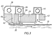
- a nozzle 14 for supplying coating gas.
- the nozzle is arranged transversely to the glass ribbon and it extends over the entire width of the latter. It comprises a section 16, of inverted U section, the edges of the walls of which are fixed to horizontal brackets 18, 20. These define between them an oblong opening 22 transverse to the ribbon and having a length equal to the width ribbon.
- a gas supply conduit 26 drilled over its entire length of holes 27.
- the gas extends into the chamber 24 where it is put at a uniform pressure and flows through the opening 22 to a channel 28 of U-shaped section.
- This channel comprises a vertical injection chamber 30 defined between an upstream profiled heel 32 and a central profiled block 34, a horizontal chamber 36, of constant thickness, included between the glass ribbon 10 and the lower face 38 of the central block which is flat and a vertical suction chamber 40 defined between the central block and a downstream profiled heel 42.
- the gas is sucked in through a transverse suction pipe 44 housed in a section 46 of inverted U section, fixed to the central block and to the upstream heel by means of consoles 48, 50 .
- the upstream heel 32 is provided with a flat lower face positioned parallel to the glass ribbon and at a distance as small as possible from the latter, for example 1 mm, in order to limit the maximum gas leakage under said heel upstream.
- the height of the horizontal chamber 36 is greater (3 to 6 mm) in order to allow the gas stream, arriving from the injection chamber 30, to flow in a laminar regime, uniformly over the entire length of the glass ribbon .
- the latter in order to prevent any possible fouling of the lower face 52 of the downstream heel 42 from being disturbing, the latter is separated from the glass ribbon, at a distance of at least 10 mm, for example between 10 and 50 mm and preferably between 10 and 30 mm and even between 10 and 20 mm. Despite this, no leakage occurs under the downstream heel because the gas stream 54 leaving the horizontal chamber 36 is blocked by a counter-current 56 of ambient gas from the bath which is sucked through the suction duct 44 at the same time as said gas stream.
- a second suction conduit 58 mounted upstream of the upstream heel 52, for sucking up the gas leaks 62 occurring under the latter. This avoids any pollution of the atmosphere of the float bath, even when the quantities of reactive gases are large.
- FIG. 2 shows a first embodiment of this complementary suction.
- the conduit 58 is mounted inside a hood whose wall 60 is sufficiently distant from the glass ribbon 10 so that a too high speed of the hot current of external atmosphere is not created due to the suction.
- This hot current would then risk, because it is placed above the effluents leaving the nozzle, to cause their decomposition by thermophoresis, which would result in the appearance of defects on the glass due to fallout on it ci of decomposing particles.
- generator of "veil” a height of several centimeters, for example 5 cm, is reserved between the hood wall 60 and the glass ribbon.
- the suction of the conduit 58 takes place in a channel 63 substantially parallel to the channel 28, extending across the ribbon of glass 10 over the entire length of the nozzle, disposed upstream of the upstream heel 32 and separated from the ambient atmosphere, in particular that of the float by an additional upstream heel 64 spaced from the glass ribbon of a height greater than that available under the upstream heel 32, namely of the order of 2 to 10 mm and, preferably, of the order of 3 to 8 mm.
- Such nozzles are particularly effective and can be installed inside the enclosure of a glass-making float bath, but they can also be installed outside the float.
Landscapes
- Chemical & Material Sciences (AREA)
- Engineering & Computer Science (AREA)
- Materials Engineering (AREA)
- Chemical Kinetics & Catalysis (AREA)
- General Chemical & Material Sciences (AREA)
- Organic Chemistry (AREA)
- Geochemistry & Mineralogy (AREA)
- Life Sciences & Earth Sciences (AREA)
- Physics & Mathematics (AREA)
- Plasma & Fusion (AREA)
- Mechanical Engineering (AREA)
- Metallurgy (AREA)
- Surface Treatment Of Glass (AREA)
- Chemical Vapour Deposition (AREA)
Claims (6)
- Düsenaufbau zur Herstellung einer Überzugsschicht durch Pyrolyse eines Gasgemisches, dessen Strömung laminar geführt ist, auf Glas und einem Glasband (10), das mit gleichbleibender Geschwindigkeit auf einem Floatbad (12) durchläuft, wobei sich die Düse in Arbeitsstellung über die gesamte Breite des Glasbandes erstreckt und eine Einblaseinrichtung (26) für das Gas, einen stromlinienförmigen zentralen Block (34), einen stromlinienförmigen, in Durchlaufrichtung des Glasbandes hinteren Vorsatz (32) und einen stromlinienförmigen vorderen Vorsatz (42), die derart an beiden Seiten des zentralen Blocks angeordnet sind, daß dem von der Einblaseinrichtung kommenden Gas ein Strömungsweg entlang eines U-förmigen Führungskanals (28) geschaffen wird, der zwischen dem hinteren Vorsatz und dem zentralen Block, der Unterseite (38) des zentralen Blocks und dem Glasband und dem zentralen Block und dem vorderen Vorsatz (42) verläuft, und eine Absaugeinrichtung (44) für das Gas umfaßt, die am Ausgang des Kanals (28) zwischen dem zentralen Block und dem vorderen Vorsatz angebracht ist, wobei der vordere Vorsatz (42) der Düse in bezug auf den zentralen Block (34) gegenüber dem Glasband (10) erhöht ist, dadurch gekennzeichnet, daß der Abstand zwischen der Unterseite (52) des vorderen Vorsatzes (42) und der Oberfläche des Glasbandes (10) 10 bis 50 mm beträgt, daß der Abstand zwischen der Unterseite (38) des zentralen Blocks (34) und der Oberfläche des Glasbandes (10) zwischen 3 und 6 mm beträgt und daß die Düse mit einer ersten Absaugeinrichtung (44) für das Gas, die am Ausgang des Kanals (28) zwischen dem zentralen Block (34) und dem vorderen Vorsatz (42) angebracht ist, und mit zweiten Absaugmitteln (58), die hinter dem hinteren Vorsatz (32) oder vor dem vorderen Vorsatz (42) angeordnet sind, ausgerüstet ist.
- Aufbau nach Anspruch 1, dadurch gekennzeichnet, daß der Abstand, der die Unterseite (32) des vorderen Vorsatzes (42) von der Oberfläche des Glasbandes (10) trennt, zwischen 10 und 30 und insbesondere zwischen 10 und 20 mm beträgt.
- Aufbau nach Anspruch 1 oder 2, dadurch gekennzeichnet, daß die zweiten Absaugmittel (58) im Inneren einer Abzugshaube (60) enthalten sind, die sich zum Glasband (10) in einer Entfernung befindet, welche die Geschwindigkeit der in den Zwischenraum zwischen der Abzugshaube (60) und dem Glasband (10) angesaugten Gasströme begrenzt.
- Aufbau nach Anspruch 3, dadurch gekennzeichnet, daß sich der untere Teil der Abzugshaube in einer Entfernung von etwa 5 cm zum Glasband (10) befindet.
- Aufbau nach Anspruch 1 oder 2, dadurch gekennzeichnet, daß die zweiten Absaugmittel (58) hinter dem hinteren Vorsatz (32) durch einen sich über die Länge der Düse erstreckenden Kanal (63) wirken, der an der hinteren Seite von einem zusätzlichen hinteren Vorsatz (64) begrenzt wird.
- Aufbau nach Anspruch 5, dadurch gekennzeichnet, daß der Abstand zwischen dem zusätzlichen hinteren Vorsatz (64) und dem Glasband (10) etwa 2 bis 10 und insbesondere etwa 3 bis 8 mm beträgt.
Applications Claiming Priority (2)
| Application Number | Priority Date | Filing Date | Title |
|---|---|---|---|
| FR9101683A FR2672519B1 (fr) | 1991-02-13 | 1991-02-13 | Buse a talon aval sureleve, pour deposer une couche de revetement sur un ruban de verre, par pyrolyse d'un melange gazeux. |
| FR9101683 | 1991-02-13 |
Publications (2)
| Publication Number | Publication Date |
|---|---|
| EP0499523A1 EP0499523A1 (de) | 1992-08-19 |
| EP0499523B1 true EP0499523B1 (de) | 1995-08-30 |
Family
ID=9409669
Family Applications (1)
| Application Number | Title | Priority Date | Filing Date |
|---|---|---|---|
| EP19920400343 Expired - Lifetime EP0499523B1 (de) | 1991-02-13 | 1992-02-11 | Düse mit angehobenem stromabwärts liegendem Absatz zur Beschichtung eines Glasbandes durch Pyrolyse eines Gasgemisches |
Country Status (5)
| Country | Link |
|---|---|
| EP (1) | EP0499523B1 (de) |
| JP (1) | JP3224580B2 (de) |
| DE (1) | DE69204316T2 (de) |
| ES (1) | ES2078677T3 (de) |
| FR (1) | FR2672519B1 (de) |
Families Citing this family (8)
| Publication number | Priority date | Publication date | Assignee | Title |
|---|---|---|---|---|
| US5356718A (en) * | 1993-02-16 | 1994-10-18 | Ppg Industries, Inc. | Coating apparatus, method of coating glass, compounds and compositions for coating glasss and coated glass substrates |
| US5599387A (en) * | 1993-02-16 | 1997-02-04 | Ppg Industries, Inc. | Compounds and compositions for coating glass with silicon oxide |
| US5863337A (en) * | 1993-02-16 | 1999-01-26 | Ppg Industries, Inc. | Apparatus for coating a moving glass substrate |
| FR2724923B1 (fr) * | 1994-09-27 | 1996-12-20 | Saint Gobain Vitrage | Technique de depot de revetements par pyrolyse de composition de gaz precurseur(s) |
| FR2736632B1 (fr) * | 1995-07-12 | 1997-10-24 | Saint Gobain Vitrage | Vitrage muni d'une couche conductrice et/ou bas-emissive |
| US6103015A (en) * | 1998-01-19 | 2000-08-15 | Libbey-Owens-Ford Co. | Symmetrical CVD coater with lower upstream exhaust toe |
| JP5124760B2 (ja) * | 2004-04-19 | 2013-01-23 | 静雄 藤田 | 成膜方法及び成膜装置 |
| JP6999478B2 (ja) | 2018-03-30 | 2022-01-18 | セコム株式会社 | マーカ及びマーカ検出システム |
Family Cites Families (2)
| Publication number | Priority date | Publication date | Assignee | Title |
|---|---|---|---|---|
| GB1507996A (en) * | 1975-06-11 | 1978-04-19 | Pilkington Brothers Ltd | Coating glass |
| CA1332281C (en) * | 1988-09-16 | 1994-10-11 | Randall L. Bauman | Temperature controlled distributor beam for chemical vapor deposition |
-
1991
- 1991-02-13 FR FR9101683A patent/FR2672519B1/fr not_active Expired - Fee Related
-
1992
- 1992-02-11 ES ES92400343T patent/ES2078677T3/es not_active Expired - Lifetime
- 1992-02-11 DE DE1992604316 patent/DE69204316T2/de not_active Expired - Fee Related
- 1992-02-11 EP EP19920400343 patent/EP0499523B1/de not_active Expired - Lifetime
- 1992-02-12 JP JP02535292A patent/JP3224580B2/ja not_active Expired - Fee Related
Also Published As
| Publication number | Publication date |
|---|---|
| DE69204316D1 (de) | 1995-10-05 |
| EP0499523A1 (de) | 1992-08-19 |
| JPH0578151A (ja) | 1993-03-30 |
| DE69204316T2 (de) | 1996-04-25 |
| ES2078677T3 (es) | 1995-12-16 |
| FR2672519A1 (fr) | 1992-08-14 |
| FR2672519B1 (fr) | 1995-04-28 |
| JP3224580B2 (ja) | 2001-10-29 |
Similar Documents
| Publication | Publication Date | Title |
|---|---|---|
| EP0499524B1 (de) | Asymmetrisches Gaszuführungsrohr zu Beschichtung von Glasbändern durch Pyrolyse einer Gasmischung | |
| BE1008560A3 (fr) | Dispositif et procede pour former un revetement par pyrolyse. | |
| LU84539A1 (fr) | Installation pour deposer en continu,sur la surface d'un substrat porte a haute temperature,une couche d'une matiere solide | |
| EP0499523B1 (de) | Düse mit angehobenem stromabwärts liegendem Absatz zur Beschichtung eines Glasbandes durch Pyrolyse eines Gasgemisches | |
| FR2542636A1 (fr) | Procede et dispositif de distribution reguliere d'un solide pulverulent sur un substrat en vue de son revetement et substrat ainsi revetu | |
| CH643219A5 (fr) | Verres susceptibles d'etre transformes en fibres. | |
| LU86666A1 (fr) | Procede et dispositif pour former un revetement sur du verre | |
| EP1025309B1 (de) | Einrichtung zur entstaubung an einer maschine zur produktion von krepp-papier | |
| EP0909342B1 (de) | Verfahren zum kontinuierlichen beschichten eines sich bewegenden substrats mit einem metalldampf | |
| CH670447A5 (de) | ||
| FR2545818A1 (fr) | Procede et dispositif de formation d'un revetement de compose metallique sur un substrat chaud en matiere vitreuse | |
| CH670817A5 (de) | ||
| EP0704249B1 (de) | Vorrichtung zur Verteilung pulverförmiger Feststoffe auf der Oberfläche eines Substrats zur Beschichtung dieses Substrates | |
| EP0199649B1 (de) | Beschichtung von Float-Glas mit thermisch zersetzbaren pulverigen Verbindungen | |
| EP0060780B1 (de) | Herstellung von mit Metalloxiden beschichtetem Flachglas durch verbessertes Sprühen | |
| EP0188962A1 (de) | Verfahren zum Beschichten von Glasbändern mit pulverförmigen Produkten und Vorrichtung dazu | |
| FR2816726A1 (fr) | Installation dans laquelle est realisee une operation necessitant un controle de l'atmosphere a l'interieur d'une enceinte | |
| LU86667A1 (fr) | Feuille de verre portant un revetement | |
| EP0060747B1 (de) | Herstellung von mit Oxiden beschichtetem Glas | |
| EP0125153A2 (de) | Verfahren und Vorrichtung zum regelmässigen Auftragen von Puder auf ein Substrat und Substrat auf diese Weise beschichtet | |
| EP0612566B1 (de) | Vorrichtung zur Verteilung von pulverförmigen Feststoffen auf ein Substrat zum Zweck seiner Beschichtung | |
| EP1649734A2 (de) | Verfahren und einrichtung zum füllen von in hohlräumen angeordneten bereichen oder zwischen spuren mit einem viskosem produkt auf einer leiterplatte und gerät mit der einrichtung | |
| CH651001A5 (fr) | Procede et dispositif d'application d'une couche de soudure sur les parties marginales metallisees d'une feuille vitreuse. | |
| FR2732039A1 (fr) | Dispositif d'essorage pneumatique d'une bande galvanisee au trempe | |
| WO2010092284A1 (fr) | Fabrication de verre plat texture au flottage |
Legal Events
| Date | Code | Title | Description |
|---|---|---|---|
| PUAI | Public reference made under article 153(3) epc to a published international application that has entered the european phase |
Free format text: ORIGINAL CODE: 0009012 |
|
| AK | Designated contracting states |
Kind code of ref document: A1 Designated state(s): BE CH DE ES FR GB IT LI LU |
|
| 17P | Request for examination filed |
Effective date: 19930108 |
|
| 17Q | First examination report despatched |
Effective date: 19940214 |
|
| RAP1 | Party data changed (applicant data changed or rights of an application transferred) |
Owner name: SAINT-GOBAIN VITRAGE |
|
| GRAA | (expected) grant |
Free format text: ORIGINAL CODE: 0009210 |
|
| AK | Designated contracting states |
Kind code of ref document: B1 Designated state(s): BE CH DE ES FR GB IT LI LU |
|
| REF | Corresponds to: |
Ref document number: 69204316 Country of ref document: DE Date of ref document: 19951005 |
|
| ITF | It: translation for a ep patent filed |
Owner name: DR. ING. A. RACHELI & C. |
|
| REG | Reference to a national code |
Ref country code: ES Ref legal event code: FG2A Ref document number: 2078677 Country of ref document: ES Kind code of ref document: T3 |
|
| GBT | Gb: translation of ep patent filed (gb section 77(6)(a)/1977) |
Effective date: 19951208 |
|
| PLBE | No opposition filed within time limit |
Free format text: ORIGINAL CODE: 0009261 |
|
| STAA | Information on the status of an ep patent application or granted ep patent |
Free format text: STATUS: NO OPPOSITION FILED WITHIN TIME LIMIT |
|
| 26N | No opposition filed | ||
| PGFP | Annual fee paid to national office [announced via postgrant information from national office to epo] |
Ref country code: CH Payment date: 19990517 Year of fee payment: 8 |
|
| PG25 | Lapsed in a contracting state [announced via postgrant information from national office to epo] |
Ref country code: LI Free format text: LAPSE BECAUSE OF NON-PAYMENT OF DUE FEES Effective date: 20000229 Ref country code: CH Free format text: LAPSE BECAUSE OF NON-PAYMENT OF DUE FEES Effective date: 20000229 |
|
| REG | Reference to a national code |
Ref country code: CH Ref legal event code: PL |
|
| REG | Reference to a national code |
Ref country code: GB Ref legal event code: IF02 |
|
| PGFP | Annual fee paid to national office [announced via postgrant information from national office to epo] |
Ref country code: LU Payment date: 20090210 Year of fee payment: 18 Ref country code: ES Payment date: 20090317 Year of fee payment: 18 |
|
| PGFP | Annual fee paid to national office [announced via postgrant information from national office to epo] |
Ref country code: DE Payment date: 20090206 Year of fee payment: 18 |
|
| PGFP | Annual fee paid to national office [announced via postgrant information from national office to epo] |
Ref country code: GB Payment date: 20090211 Year of fee payment: 18 |
|
| PGFP | Annual fee paid to national office [announced via postgrant information from national office to epo] |
Ref country code: BE Payment date: 20090220 Year of fee payment: 18 |
|
| PGFP | Annual fee paid to national office [announced via postgrant information from national office to epo] |
Ref country code: IT Payment date: 20090217 Year of fee payment: 18 |
|
| PGFP | Annual fee paid to national office [announced via postgrant information from national office to epo] |
Ref country code: FR Payment date: 20090213 Year of fee payment: 18 |
|
| BERE | Be: lapsed |
Owner name: *SAINT-GOBAIN VITRAGE Effective date: 20100228 |
|
| GBPC | Gb: european patent ceased through non-payment of renewal fee |
Effective date: 20100211 |
|
| REG | Reference to a national code |
Ref country code: FR Ref legal event code: ST Effective date: 20101029 |
|
| PG25 | Lapsed in a contracting state [announced via postgrant information from national office to epo] |
Ref country code: FR Free format text: LAPSE BECAUSE OF NON-PAYMENT OF DUE FEES Effective date: 20100301 |
|
| PG25 | Lapsed in a contracting state [announced via postgrant information from national office to epo] |
Ref country code: DE Free format text: LAPSE BECAUSE OF NON-PAYMENT OF DUE FEES Effective date: 20100901 Ref country code: BE Free format text: LAPSE BECAUSE OF NON-PAYMENT OF DUE FEES Effective date: 20100228 |
|
| REG | Reference to a national code |
Ref country code: ES Ref legal event code: FD2A Effective date: 20110325 |
|
| PG25 | Lapsed in a contracting state [announced via postgrant information from national office to epo] |
Ref country code: IT Free format text: LAPSE BECAUSE OF NON-PAYMENT OF DUE FEES Effective date: 20100211 Ref country code: GB Free format text: LAPSE BECAUSE OF NON-PAYMENT OF DUE FEES Effective date: 20100211 |
|
| PG25 | Lapsed in a contracting state [announced via postgrant information from national office to epo] |
Ref country code: ES Free format text: LAPSE BECAUSE OF NON-PAYMENT OF DUE FEES Effective date: 20110314 |
|
| PG25 | Lapsed in a contracting state [announced via postgrant information from national office to epo] |
Ref country code: ES Free format text: LAPSE BECAUSE OF NON-PAYMENT OF DUE FEES Effective date: 20100212 |
|
| PG25 | Lapsed in a contracting state [announced via postgrant information from national office to epo] |
Ref country code: LU Free format text: LAPSE BECAUSE OF NON-PAYMENT OF DUE FEES Effective date: 20100211 |