EP0498947B1 - Brennkraftmaschine mit Abgasrückführung - Google Patents
Brennkraftmaschine mit Abgasrückführung Download PDFInfo
- Publication number
- EP0498947B1 EP0498947B1 EP91120241A EP91120241A EP0498947B1 EP 0498947 B1 EP0498947 B1 EP 0498947B1 EP 91120241 A EP91120241 A EP 91120241A EP 91120241 A EP91120241 A EP 91120241A EP 0498947 B1 EP0498947 B1 EP 0498947B1
- Authority
- EP
- European Patent Office
- Prior art keywords
- exhaust gas
- exhaust
- pipe
- gas feedback
- throttle valve
- Prior art date
- Legal status (The legal status is an assumption and is not a legal conclusion. Google has not performed a legal analysis and makes no representation as to the accuracy of the status listed.)
- Expired - Lifetime
Links
Images
Classifications
-
- F—MECHANICAL ENGINEERING; LIGHTING; HEATING; WEAPONS; BLASTING
- F02—COMBUSTION ENGINES; HOT-GAS OR COMBUSTION-PRODUCT ENGINE PLANTS
- F02D—CONTROLLING COMBUSTION ENGINES
- F02D9/00—Controlling engines by throttling air or fuel-and-air induction conduits or exhaust conduits
- F02D9/04—Controlling engines by throttling air or fuel-and-air induction conduits or exhaust conduits concerning exhaust conduits
-
- F—MECHANICAL ENGINEERING; LIGHTING; HEATING; WEAPONS; BLASTING
- F01—MACHINES OR ENGINES IN GENERAL; ENGINE PLANTS IN GENERAL; STEAM ENGINES
- F01N—GAS-FLOW SILENCERS OR EXHAUST APPARATUS FOR MACHINES OR ENGINES IN GENERAL; GAS-FLOW SILENCERS OR EXHAUST APPARATUS FOR INTERNAL COMBUSTION ENGINES
- F01N1/00—Silencing apparatus characterised by method of silencing
- F01N1/16—Silencing apparatus characterised by method of silencing by using movable parts
- F01N1/165—Silencing apparatus characterised by method of silencing by using movable parts for adjusting flow area
-
- F—MECHANICAL ENGINEERING; LIGHTING; HEATING; WEAPONS; BLASTING
- F01—MACHINES OR ENGINES IN GENERAL; ENGINE PLANTS IN GENERAL; STEAM ENGINES
- F01N—GAS-FLOW SILENCERS OR EXHAUST APPARATUS FOR MACHINES OR ENGINES IN GENERAL; GAS-FLOW SILENCERS OR EXHAUST APPARATUS FOR INTERNAL COMBUSTION ENGINES
- F01N13/00—Exhaust or silencing apparatus characterised by constructional features ; Exhaust or silencing apparatus, or parts thereof, having pertinent characteristics not provided for in, or of interest apart from, groups F01N1/00 - F01N5/00, F01N9/00, F01N11/00
-
- F—MECHANICAL ENGINEERING; LIGHTING; HEATING; WEAPONS; BLASTING
- F02—COMBUSTION ENGINES; HOT-GAS OR COMBUSTION-PRODUCT ENGINE PLANTS
- F02M—SUPPLYING COMBUSTION ENGINES IN GENERAL WITH COMBUSTIBLE MIXTURES OR CONSTITUENTS THEREOF
- F02M26/00—Engine-pertinent apparatus for adding exhaust gases to combustion-air, main fuel or fuel-air mixture, e.g. by exhaust gas recirculation [EGR] systems
- F02M26/13—Arrangement or layout of EGR passages, e.g. in relation to specific engine parts or for incorporation of accessories
- F02M26/14—Arrangement or layout of EGR passages, e.g. in relation to specific engine parts or for incorporation of accessories in relation to the exhaust system
-
- F—MECHANICAL ENGINEERING; LIGHTING; HEATING; WEAPONS; BLASTING
- F02—COMBUSTION ENGINES; HOT-GAS OR COMBUSTION-PRODUCT ENGINE PLANTS
- F02M—SUPPLYING COMBUSTION ENGINES IN GENERAL WITH COMBUSTIBLE MIXTURES OR CONSTITUENTS THEREOF
- F02M26/00—Engine-pertinent apparatus for adding exhaust gases to combustion-air, main fuel or fuel-air mixture, e.g. by exhaust gas recirculation [EGR] systems
- F02M26/52—Systems for actuating EGR valves
- F02M26/59—Systems for actuating EGR valves using positive pressure actuators; Check valves therefor
- F02M26/61—Systems for actuating EGR valves using positive pressure actuators; Check valves therefor in response to exhaust pressure
- F02M26/615—Systems for actuating EGR valves using positive pressure actuators; Check valves therefor in response to exhaust pressure the exhaust back pressure
-
- F—MECHANICAL ENGINEERING; LIGHTING; HEATING; WEAPONS; BLASTING
- F02—COMBUSTION ENGINES; HOT-GAS OR COMBUSTION-PRODUCT ENGINE PLANTS
- F02M—SUPPLYING COMBUSTION ENGINES IN GENERAL WITH COMBUSTIBLE MIXTURES OR CONSTITUENTS THEREOF
- F02M26/00—Engine-pertinent apparatus for adding exhaust gases to combustion-air, main fuel or fuel-air mixture, e.g. by exhaust gas recirculation [EGR] systems
- F02M2026/001—Arrangements; Control features; Details
- F02M2026/004—EGR valve controlled by a temperature signal or an air/fuel ratio (lambda) signal
Definitions
- the invention relates to an internal combustion engine with exhaust gas recirculation according to the preamble of claim 1, in which a controllable amount of exhaust gases dependent on operating conditions is returned to the intake system.
- DE-OS 34 19 917 From DE-OS 34 19 917 it is known to supply a proportion of exhaust gases to the intake air under certain operating conditions. With this recirculation of exhaust gases, a number of positive effects that are becoming increasingly important in internal combustion engine construction, for example minimizing pollutant emissions, are achieved. The best results are achieved with exact control of the quantity of the recirculated exhaust gases in relation to the quantity of the sucked in or supplied fresh gases, taking into account the respective operating conditions such as load, speed, temperature. It is also known from DE-OS 34 19 917 to regulate the amount of exhaust gas recirculation using a plurality of valves and throttle valves in the exhaust gas recirculation line and in the intake system.
- valves or throttle valves in the exhaust gas recirculation line are only suitable for reducing or blocking the maximum flow rate, which depends on the pressure drop between the intake system and the exhaust system.
- the intake cross section can be narrowed, as in the solution mentioned, in order to increase the intake vacuum and thereby the pressure drop between the intake system and the exhaust system.
- a sufficient effective increase in intake vacuum, especially in the Partial load range with low speed relevant for exhaust gas recovery leads to a deterioration of the engine efficiency.
- the invention has for its object to further develop the known exhaust gas recirculation devices in such a way that the maximum exhaust gas recirculation quantity is increased at low speed, in particular in the exhaust gas recirculation-relevant partial load range, without additional complex control and actuation devices.
- the object is achieved by the features of claim 1.
- the invention is therefore based on increasing the recirculation quantity with constant or minimized cross sections of the exhaust gas recirculation line by a temperature-dependent increase in the exhaust gas back pressure, in particular in the exhaust gas recirculation-relevant partial load range.
- a throttle valve or a throttle valve can be arranged immediately after each connection of an exhaust gas recirculation line after the separate exhaust pipes have been brought together.
- several throttle valves can be arranged one behind the other.
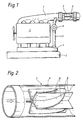
- FIG. 1 representing an internal combustion engine with exhaust gas recirculation
- FIG. 2 a throttle valve according to the invention.
- An exhaust gas recirculation line 3 is connected to an exhaust manifold 1 of an internal combustion engine 2 and opens into the mixing chamber 4, in which the fresh air flowing in from the air filter 5 is mixed with the exhaust gases flowing in via the exhaust gas recirculation line 3.
- the passage of the exhaust gas recirculation line 3 can be controlled by means of a valve 6.
- an intake throttle not shown, arranged upstream of the air filter 5 or arranged between the air filter 5 and the mixing chamber 4 can reduce the intake cross section.
- the valve 6 and the intake throttle are activated as a function of manipulated variables which are formed by evaluating operating parameters such as the load condition, speed and temperature.
- a temperature-dependent throttle valve 7 which is described in more detail in FIG. 2, is arranged downstream of the exhaust gas recirculation line 3 in the exhaust pipe 9.
- This throttle valve 7 consists essentially of at least four struts 8, which are fixed radially or in a star shape in the exhaust pipe 9 and are firmly connected to one another on the central longitudinal axis of the exhaust pipe 9, so that a rigid body dividing the cross section into circular segments is formed in the exhaust pipe 9, the Length extends over the entire length of the throttle valve 7.
- At the upstream ends of the struts 8 are over the entire possible width of the Central longitudinal axis to the wall of the exhaust pipe 9 bimetal plates 10, in the exhaust longitudinal direction against the struts 8, rigidly attached.
- These bi-metal sheets 10 taper downstream in their width in such a way that they completely or almost completely close the respective segment of the circle at low exhaust gas temperatures as shown in FIG. 2 in the curved state.
- a limitation of the maximum dynamic pressure is given by an appropriate design of the thickness and thus the rigidity and the elasticity of the bimetal plates 10, in that the bimetal plates 10 are bent against their closing direction when the intended dynamic pressure is exceeded.
- Changes in the load conditions in the direction of increasing the mean pressure P e lead to an immediate increase in the exhaust gas temperatures and thus with a short time delay for stretching and applying the bi-metal sheets 10 to the struts 8.
- the circle segments are thus released for unhindered exhaust gas passage and the dynamic pressure drops the unthrottled measure. This is sufficient for the small amounts of exhaust gas to be recycled under these operating conditions now there is a slight pressure drop.
- throttle valve 7 is advantageously arranged immediately after the outlet of the exhaust gas recirculation line 3, but the maximum exhaust gas temperature must not exceed the upper limit of the temperature capacity of the throttle valve 7.
- throttle valves 7 according to the invention are either arranged in each exhaust pipe analogous to a single-flow system or a throttle valve 7 after the exhaust pipes have been brought together.
- several throttle valves can be arranged one behind the other.
Landscapes
- Engineering & Computer Science (AREA)
- Chemical & Material Sciences (AREA)
- Combustion & Propulsion (AREA)
- Mechanical Engineering (AREA)
- General Engineering & Computer Science (AREA)
- Exhaust-Gas Circulating Devices (AREA)
Description
- Die Erfindung betrifft eine Brennkraftmaschine mit Abgasrückführung gemäß dem Oberbegriff von Anspruch 1, bei der eine von Betriebsbedingungen abhängige steuerbare Menge von Abgasen in das Ansaugsystem zurückgeführt wird.
- Aus der DE-OS 34 19 917 ist es bekannt, einen Anteil von Abgasen unter bestimmten Betriebsbedingungen der Ansaugluft zuzuführen. Mit dieser Rückführung von Abgasen werden eine Anzahl im Verbrennungsmotorenbau zunehmend an Bedeutung gewinnende positive Effekte z.B. eine Minimierung des Schadstoffausstoßes erreicht. Die besten Ergebnisse werden dabei bei exakter Steuerung der Menge der zurückgeführten Abgase im Verhältnis zur Menge der angesaugten bzw. zugeführten Frischgase unter Einbeziehung der jeweiligen Betriebsbedingungen wie Last, Drehzahl, Temperatur erreicht. Ferner ist es aus der DE-OS 34 19 917 bekannt, die Abgasrückführungsmenge unter Verwendung einer Mehrzahl von Ventilen und Drosselklappen in der Abgasrückführungsleitung und im Ansaugsystem zu regeln. Ventile oder Drosselklappen in der Abgasrückführungsleitung sind jedoch nur geeignet, die vom Druckgefälle zwischen Ansaugsystem und Auspuffanlage abhängige maximale Strömungsmenge zu reduzieren bzw. zu sperren. Um die Strömungsmenge zu erhöhen, k ann wie in der genannten Lösung, der Ansaugquerschnitt verengt werden, um den Ansaugunterdruck und dadurch das Druckgefälle zwischen Ansaugsystem und Auspuffanlage zu erhöhen. Eine ausreichende wirksame Erhöhung des Ansaugunterdruckes insbesondere im abgasrückrungsrelevanten Teillastbereich mit geringer Drehzahl führt jedoch zu einer Verschlechterung des motorischen Wirkungsgrades. Diese für eine optimale Abgasrückführung nachteiligen Bedingungen zwingen zu aufwendigen und großbauenden Abgasrückführungssystem mit sehr großen Strömungsquerschnitten. Zur Erhöhung der Abgasrückführrate ist es aus der DE-OS 37 22 970, die den nächstkommenden Stand der Technik bildet, bekannt, den Abgasgegendruck mittels einer im Abgasrohr angeordneten Drosselklappe anzuheben. Derartige Drosseleinrichtungen in der Abgasleitung weisen jedoch den Nachteil auf, daß zur Funktion dieser Drosselklappe relativ aufwendige Betätigungs- und Steuereinrichtungen erforderlich sind.
- Der Erfindung liegt die Aufgabe zugrunde, die bekannten Abgasrückführungseinrichtungen derart weiterzubilden, daß ohne zusätzliche aufwendige Steuer- und Betätigungseinrichtungen die maximale Abgasrückführungsmenge besonders in dem abgasrückführungsrelevanten Teillastbereich bei niedriger Drehzahl erhöht wird.
- Die Aufgabe wird erfindungsgemäß durch die Merkmale des 1. Anspruches gelöst. Die Erfindung beruht also darauf, durch eine temperaturabhängige Erhöhung des Abgasgegendruckes insbesondere im abgasrückführungsrelevanten Teillastbereich die Rückführungsmenge bei gleichbleibenden oder minimierten Querschnitten der Abgasrückführungsleitung zu erhöhen.
- Aus der DE-PS 510 960 und dem DE-GM 73 01 889 ist es bekannt, mittels temperaturabhängig geregelter Drosseleinrichtungen die Durchflußmenge eines Mediums zu drosseln bzw. den Staudruck in einem Auspuff zu erhöhen. Diese Lösungen geben jedoch keinen Hinweis darauf, bei Brennkraftmaschinen mit Abgasrückführung die Rückführungsmenge zu beeinflussen.
- Bei mehrflutigen Auspuffanlagen kann erfindungsgemäß unmittelbar nach jeden Anschluß einer Abgasrückführungsleitung ein Drosselventil oder ein Drosselventil nach der Zusammenführung der getrennten Auspuffrohre angeordnet sein. Erfindungsgemäß können mehrere Drosselventile hintereinander angeordnet sein.
- Die Erfindung wird im folgenden anhand von Prinzipdarstellungen weiter erläutert, wobei Fig. 1 eine Brennkraftmaschine mit einer Abgasrückführung und Fig. 2 ein erfindungsgemäßes Drosselventil darstellt.
- An einem Auspuffkrümmer 1 einer Brennkraftmaschine 2 ist eine Abgasrückführungsleitung 3 angeschlossen und mündet in die Mischkammer 4, in der die vom Luftfilter 5 einströmende Frischluft mit den über die Abgasrückführungsleitung 3 zuströmenden Abgasen gemischt wird. Der Durchlaß der Abgasrückführungsleitung 3 ist mittels eines Ventiles 6 steuerbar. Weiterhin kann eine dem Luftfilter 5 vorgelagerte oder zwischen Luftfilter 5 und Mischkammer 4 angeordnete nicht dargestellte Ansaugdrossel den Ansaugquerschnitt vermindern. Die Ansteuerung des Ventiles 6 und der Ansaugdrossel geschieht in Abhängigkeit von Stellgrößen, die in Auswertung von Betriebsparametern wie Lastzustand, Drehzahl und Temperatur gebildet werden.
- Erfindungsgemäß ist im Auspuffrohr 9 stromab nach dem Anschluß der Abgasrückführungsleitung 3 ein in Fig. 2 näher beschriebenes temperaturabhängig wirkendes Drosselventil 7 angeordnet. Dieses Drosselventil 7 besteht im wesentlichen aus mindestens vier Streben 8, die radial bzw. sternförmig in dem Auspuffrohr 9 befestigt und auf der Mittellängsachse des Auspuffrohres 9 miteinander fest verbunden sind, so daß im Auspuffrohr 9 ein starrer den Querschnitt in Kreissegmente unterteilender Körper entsteht, dessen Länge sich über die gesamte Länge des Drosselventiles 7 erstreckt. An den stromauf liegenden Enden der Streben 8 sind über die gesamte mögliche Breite von der Mittellängsachse bis zur Wandung des Auspuffrohres 9 Bi-Metallbleche 10, in Auspufflängsrichtung an den Streben 8 anliegend, starr befestigt. Diese Bi-Metallbleche 10 verjüngen sich stromab in ihrer Breite dergestalt, daß sie bei geringen Abgastemperaturen entsprechend der Darstellung in Fig. 2 im gekrümmten Zustand das jeweilige Kreissegment vollständig oder nahezu vollständig verschließen.
- Mit Hilfe dieser Vorrichtung wird ohne aufwendige Regelung von außen eine Erhöhung des Staudruckes der Abgase speziell in den Betriebsbereichen erreicht, in denen eine maximale Abgasmenge zurückgeführt werden soll. Dies ist in unteren Drehzahlbereichen bei geringem Mitteldruck Pe also bei Teillast der Fall. Gerade diese Betriebsbereiche zeichnen sich jedoch durch relativ geringe Abgasmengen mit niedrigen Temperaturen aus. Durch das bei diesen Betriebsbereichen aufgrund der geringen Abgastemperaturen geschlossene Drosselventil 7 wird nun erfindungsgemäß der Abgasgegendruck und damit das Druckgefälle zum Ansaugsystem derart vergrößert, daß die optimale Abgasmenge problemlos rückführbar ist, wobei der Querschnitt der Abgasrückführungsleitung 3 im Vergleich zu herkömmlichen Abgasrückführungsanlagen gleich oder geringer dimensioniert sein kann. Eine Begrenzung des maximalen Staudruckes ist durch eine entsprechende Auslegung der Dicke und damit der Steifigkeit sowie der Elastizität der Bi-Metallbleche 10 gegeben, indem die Bi-Metallbleche 10 bei Überschreitung des vorgesehenen Staudruckes entgegen ihrer Schließrichtung aufgebogen werden. Veränderungen der Lastbedingungen in Richtung Erhöhung des Mitteldruckes Pe führen zur sofortigen Erhöhung der Abgastemperaturen und damit mit geringer zeitlicher Verzögerung zum Strecken und Anlegen der Bi-Metallbleche 10 an die Streben 8. Die Kreissegmente werden somit für den ungehinderten Abgasdurchtritt freigegeben und der Staudruck sinkt auf das ungedrosselte Maß. Für die bei diesen Betriebsbedingungen geringen Mengen zurückzuführenden Abgases reicht das nun herrschende geringe Druckgefälle. Das Drosselventil 7 ist vorteilhaft unmittelbar nach dem Abgang der Abgasrückführungsleitung 3 angeordnet, wobei jedoch die maximale Abgastemperatur die Obergrenze der Temperaturbelastbarkeit des Drosselventiles 7 nicht übersteigen darf. Bei mehrflutigen Auspuffanlagen mit mehreren Abgasrückführungsleitungen sind erfindungsgemäß Drosselventile 7 entweder in jedem Auspuffrohr analog einer einflutigen Anlage oder ein Drosselventil 7 nach Zusammenführung der Auspuffrohre angeordnet.
Zur weiteren Erhöhung des Abgasgegendruckes können mehrere Drosselventile hintereinander angeordnet sein.
Claims (5)
- Brennkraftmaschine (2) mit Abgasrückführung mit einer zwischen Auspuff- und Ansauganlage angeordneten Abgasrückführungsleitung (3), mit einem in der Abgasrückführungsleitung (3) angeordneten Steuerventil (6) und mit einem in der Auspuffanlage stromab des Anschlusses der Abgasrückführungsleitung (3) angeordneten Drosselventil (7), von dem unterhalb einer vorgegebenen Abgastemperatur der Querschnitt des Auspuffrohres (9) weitgehend gesperrt und bei ansteigender Abgastemperatur kontinuierlich freigegeben wird,
dadurch gekennzeichnet,
daß das Drosselventil (7) aus einem unter der Wirkung der Abgastemperatur sich selbst steuernden Bi-Metall-Ventil gebildet ist, welches aus einer Mehrzahl im Auspuffrohr (9) radial bzw. sternförmig angeordneter und dabei den freien Querschnitt des Auspuffrohres (9) in Kreissegmente unterteilende Streben (8) besteht, die sich über die gesamte Länge des Drosselventiles (7) erstrecken und auf der Mittellängsachse des Auspuffrohres (9) miteinander sowie an ihrer Außenseite mit der Wandung des Auspuffrohres (9) verbunden sind und daß an den stromauf liegenden Enden der Streben (8) sich stromab verjüngende Bi-Metallbleche (10) biegesteif befestigt sind, wobei diese im warmen Zustand einen annähernd keinen Strömungswiderstand bietende, in Auspufflängsrichtung gestreckte an den Streben (8) anliegende Form einnehmen und im kalten Zustand derartig gekrümmt sind, daß durch jedes Bi-Metallblech (10) der Querschnitt jeweils eines durch die Streben (8) gebildeten Kreissegmentes des Auspuffrohrquerschnittes verschlossen ist. - Brennkraftmaschine mit Abgasrückführung nach Anspruch 1,
dadurch gekennzeichnet,
daß eine Begrenzung des sich bei geschlossenen Drosselventil (7) maximal einstellenden Staudruckes durch entsprechende Auslegung der Steifheit bzw. Elastizität der Bi-Metallbleche (10) gesichert ist. - Brennkraftmaschine mit Abgasrückführung nach Anspruch 1,
dadurch gekennzeichnet,
daß bei einer mehrflutigen Auspuffanlage mit mehreren Abgasrückführungsleitungen (3) unmittelbar nach jedem Anschluß einer Abgasrückführungsleitung (3) ein Drosselventil (7) angeordnet ist. - Brennkraftmaschine mit Abgasrückführung nach Anspruch 1,
dadurch gekennzeichnet,
daß in einer mehrflutigen Auspuffanlage mit mehreren Abgasrückführungsleitungen (3) ein Drosselventil (7) nach der Zusammenführung der getrennten Auspuffrohre angeordnet ist. - Brennkraftmaschine mit Abgasrückführung nach Anspruch 1,
dadurch gekennzeichnet,
daß mehrere Drosselventile (7) hintereinander angeordnet sind.
Applications Claiming Priority (2)
| Application Number | Priority Date | Filing Date | Title |
|---|---|---|---|
| DE4104127 | 1991-02-12 | ||
| DE4104127A DE4104127C1 (de) | 1991-02-12 | 1991-02-12 |
Publications (2)
| Publication Number | Publication Date |
|---|---|
| EP0498947A1 EP0498947A1 (de) | 1992-08-19 |
| EP0498947B1 true EP0498947B1 (de) | 1993-09-29 |
Family
ID=6424826
Family Applications (1)
| Application Number | Title | Priority Date | Filing Date |
|---|---|---|---|
| EP91120241A Expired - Lifetime EP0498947B1 (de) | 1991-02-12 | 1991-11-27 | Brennkraftmaschine mit Abgasrückführung |
Country Status (2)
| Country | Link |
|---|---|
| EP (1) | EP0498947B1 (de) |
| DE (1) | DE4104127C1 (de) |
Family Cites Families (9)
| Publication number | Priority date | Publication date | Assignee | Title |
|---|---|---|---|---|
| FR595814A (fr) * | 1925-03-26 | 1925-10-09 | Perfectionnements aux moteurs à explosions et à combustion interne | |
| DE510960C (de) * | 1928-09-26 | 1930-10-24 | Willy Brandegger Dipl Ing | Einrichtung zur Durchflussregelung in Rohrleitungen |
| GB1043865A (en) * | 1962-07-12 | 1966-09-28 | Michael Guillermo May | Improvements in and relating to internal combustion engines |
| DE7301889U (de) * | 1973-01-19 | 1976-04-22 | Daimler-Benz Ag, 7000 Stuttgart | Brennkraftmaschine mit einer abgasleitung |
| FR2271393A1 (de) * | 1974-02-01 | 1975-12-12 | Alsacienne Constr Meca | |
| JPS5844847B2 (ja) * | 1975-12-25 | 1983-10-05 | 株式会社日本自動車部品総合研究所 | ナイネンキカンヨウハイキガスジヨウカソウチ |
| DE2750537A1 (de) * | 1977-11-11 | 1979-05-17 | Audi Nsu Auto Union Ag | Verfahren zum vermindern des verbrennungsgeraeusches von dieselmotoren im leerlauf sowie vorrichtung zum durchfuehren des verfahrens |
| DE3419917A1 (de) * | 1983-06-08 | 1984-12-13 | AVL Gesellschaft für Verbrennungskraftmaschinen und Messtechnik mbH, Prof. Dr.Dr.h.c. Hans List, Graz | Brennkraftmaschine |
| DE3722970A1 (de) * | 1986-08-06 | 1988-02-11 | Volkswagen Ag | Verfahren und einrichtung zum reinigen eines partikelfilters, insbesondere eines russfilters |
-
1991
- 1991-02-12 DE DE4104127A patent/DE4104127C1/de not_active Expired - Fee Related
- 1991-11-27 EP EP91120241A patent/EP0498947B1/de not_active Expired - Lifetime
Also Published As
| Publication number | Publication date |
|---|---|
| DE4104127C1 (de) | 1992-02-20 |
| EP0498947A1 (de) | 1992-08-19 |
Similar Documents
| Publication | Publication Date | Title |
|---|---|---|
| EP2014887A2 (de) | Kombiniertes Rückschlag- und Steuerventil | |
| EP2728156B1 (de) | Regelvorrichtung für eine Verbrennungskraftmaschine | |
| EP2211048B1 (de) | Abgasklappenvorrichtung und Abgaswärmerückgewinnungssystem einer verbrennungskraftmaschine | |
| WO2017108162A1 (de) | Abgasführungsabschnitt für einen abgasturbolader und verfahren zum betreiben eines abgasturboladers | |
| DE3738538C2 (de) | Katalysatoreinrichtung zur Abgasreinigung | |
| WO2021094112A1 (de) | Brennkraftmaschine mit sekundärluftsystem | |
| DE3822954C2 (de) | Abgasrückführeinrichtung | |
| DE2252980A1 (de) | Treibstoffverteilungssystem fuer gasturbinentriebwerke | |
| DE102020213993A1 (de) | Ventil und Vorrichtung zum Erhitzen von Öl mittels Abgaswärme | |
| DE102012103311B4 (de) | Ventilvorrichtung für eine Verbrennungskraftmaschine | |
| EP3631187B1 (de) | Abgasrückführvorrichtung für eine verbrennungskraftmaschine | |
| EP0498947B1 (de) | Brennkraftmaschine mit Abgasrückführung | |
| DE102010006038A1 (de) | Vorrichtung zur Regelung eines Fluidstroms | |
| DE3404769A1 (de) | Ventil zum einbau in einen kruemmer einer fluidleitung einer brennkraftmaschine | |
| DE2364903C2 (de) | Vergaser für Brennkraftmaschinen | |
| EP2610474B1 (de) | Niederdruck-Abgasrückführventil | |
| DE3716661A1 (de) | Vorrichtung zur steuerung mindestens eines drosselquerschnittes an mindestens einer steueroeffnung | |
| DE102020106983B3 (de) | Mischeranordnung und Verfahren zum Betreiben einer Mischeranordnung | |
| AT520807B1 (de) | Abgasnachbehandlungsvorrichtung für eine brennkraftmaschine | |
| EP3837472B1 (de) | Anordnung mit zwei brennern | |
| DE3113943A1 (de) | "gleichdruckvergaser fuer brennkraftmaschinen" | |
| WO2008095214A1 (de) | Vorrichtung zur abgasrückführung für einen verbrennungsmotor | |
| DE102006003447B4 (de) | Abgaskühler für eine Brennkraftmaschine | |
| DE102017120236B4 (de) | Staudruckklappe | |
| DE102016225279A1 (de) | Abgasnachbehandlungsanordnung und Verfahren zum Betreiben einer Abgasnachbehandlungsanordnung |
Legal Events
| Date | Code | Title | Description |
|---|---|---|---|
| PUAI | Public reference made under article 153(3) epc to a published international application that has entered the european phase |
Free format text: ORIGINAL CODE: 0009012 |
|
| 17P | Request for examination filed |
Effective date: 19920401 |
|
| AK | Designated contracting states |
Kind code of ref document: A1 Designated state(s): FR GB IT SE |
|
| 17Q | First examination report despatched |
Effective date: 19921030 |
|
| ITF | It: translation for a ep patent filed |
Owner name: BARZANO' E ZANARDO ROMA S.P.A. |
|
| GRAA | (expected) grant |
Free format text: ORIGINAL CODE: 0009210 |
|
| AK | Designated contracting states |
Kind code of ref document: B1 Designated state(s): FR GB IT SE |
|
| GBT | Gb: translation of ep patent filed (gb section 77(6)(a)/1977) |
Effective date: 19931020 |
|
| ET | Fr: translation filed | ||
| ITTA | It: last paid annual fee | ||
| PLBE | No opposition filed within time limit |
Free format text: ORIGINAL CODE: 0009261 |
|
| STAA | Information on the status of an ep patent application or granted ep patent |
Free format text: STATUS: NO OPPOSITION FILED WITHIN TIME LIMIT |
|
| 26N | No opposition filed | ||
| EAL | Se: european patent in force in sweden |
Ref document number: 91120241.4 |
|
| PGFP | Annual fee paid to national office [announced via postgrant information from national office to epo] |
Ref country code: GB Payment date: 19971112 Year of fee payment: 7 |
|
| PGFP | Annual fee paid to national office [announced via postgrant information from national office to epo] |
Ref country code: FR Payment date: 19971121 Year of fee payment: 7 |
|
| PGFP | Annual fee paid to national office [announced via postgrant information from national office to epo] |
Ref country code: SE Payment date: 19971126 Year of fee payment: 7 |
|
| REG | Reference to a national code |
Ref country code: FR Ref legal event code: TP |
|
| REG | Reference to a national code |
Ref country code: GB Ref legal event code: 732E |
|
| PG25 | Lapsed in a contracting state [announced via postgrant information from national office to epo] |
Ref country code: GB Free format text: LAPSE BECAUSE OF NON-PAYMENT OF DUE FEES Effective date: 19981127 |
|
| PG25 | Lapsed in a contracting state [announced via postgrant information from national office to epo] |
Ref country code: SE Free format text: LAPSE BECAUSE OF NON-PAYMENT OF DUE FEES Effective date: 19981128 |
|
| GBPC | Gb: european patent ceased through non-payment of renewal fee |
Effective date: 19981127 |
|
| PG25 | Lapsed in a contracting state [announced via postgrant information from national office to epo] |
Ref country code: FR Free format text: LAPSE BECAUSE OF NON-PAYMENT OF DUE FEES Effective date: 19990730 |
|
| EUG | Se: european patent has lapsed |
Ref document number: 91120241.4 |
|
| REG | Reference to a national code |
Ref country code: FR Ref legal event code: ST |
|
| PG25 | Lapsed in a contracting state [announced via postgrant information from national office to epo] |
Ref country code: IT Free format text: LAPSE BECAUSE OF NON-PAYMENT OF DUE FEES;WARNING: LAPSES OF ITALIAN PATENTS WITH EFFECTIVE DATE BEFORE 2007 MAY HAVE OCCURRED AT ANY TIME BEFORE 2007. THE CORRECT EFFECTIVE DATE MAY BE DIFFERENT FROM THE ONE RECORDED. Effective date: 20051127 |