EP0498554B1 - Methods and apparatus for ventilating carriages - Google Patents
Methods and apparatus for ventilating carriages Download PDFInfo
- Publication number
- EP0498554B1 EP0498554B1 EP92300724A EP92300724A EP0498554B1 EP 0498554 B1 EP0498554 B1 EP 0498554B1 EP 92300724 A EP92300724 A EP 92300724A EP 92300724 A EP92300724 A EP 92300724A EP 0498554 B1 EP0498554 B1 EP 0498554B1
- Authority
- EP
- European Patent Office
- Prior art keywords
- duct
- carriage
- shutter
- ventilating
- air flow
- Prior art date
- Legal status (The legal status is an assumption and is not a legal conclusion. Google has not performed a legal analysis and makes no representation as to the accuracy of the status listed.)
- Expired - Lifetime
Links
- 238000000034 method Methods 0.000 title claims description 11
- 238000007664 blowing Methods 0.000 claims description 8
- 230000007547 defect Effects 0.000 claims description 5
- 238000009423 ventilation Methods 0.000 description 20
- 238000011144 upstream manufacturing Methods 0.000 description 5
- 238000006073 displacement reaction Methods 0.000 description 3
- 238000012544 monitoring process Methods 0.000 description 3
- 229910000831 Steel Inorganic materials 0.000 description 2
- 238000005452 bending Methods 0.000 description 2
- 230000007423 decrease Effects 0.000 description 2
- 238000010586 diagram Methods 0.000 description 2
- 239000010959 steel Substances 0.000 description 2
- 239000003990 capacitor Substances 0.000 description 1
- 238000010276 construction Methods 0.000 description 1
- 238000011109 contamination Methods 0.000 description 1
- 230000010485 coping Effects 0.000 description 1
- 230000001419 dependent effect Effects 0.000 description 1
- 238000001514 detection method Methods 0.000 description 1
- 230000005611 electricity Effects 0.000 description 1
- 238000002955 isolation Methods 0.000 description 1
- 239000002184 metal Substances 0.000 description 1
- 238000012986 modification Methods 0.000 description 1
- 230000004048 modification Effects 0.000 description 1
- 230000002035 prolonged effect Effects 0.000 description 1
- 230000004044 response Effects 0.000 description 1
- 230000000630 rising effect Effects 0.000 description 1
- 238000005070 sampling Methods 0.000 description 1
- 230000035807 sensation Effects 0.000 description 1
- 238000004088 simulation Methods 0.000 description 1
- 229910001220 stainless steel Inorganic materials 0.000 description 1
- 239000010935 stainless steel Substances 0.000 description 1
- 230000001360 synchronised effect Effects 0.000 description 1
Images


Classifications
-
- B—PERFORMING OPERATIONS; TRANSPORTING
- B61—RAILWAYS
- B61D—BODY DETAILS OR KINDS OF RAILWAY VEHICLES
- B61D27/00—Heating, cooling, ventilating, or air-conditioning
-
- B—PERFORMING OPERATIONS; TRANSPORTING
- B61—RAILWAYS
- B61D—BODY DETAILS OR KINDS OF RAILWAY VEHICLES
- B61D27/00—Heating, cooling, ventilating, or air-conditioning
- B61D27/0009—Means for controlling or equalizing air pressure shocks in trains, e.g. when passing or crossing in tunnels
Definitions
- This invention relates to methods and apparatus for ventilating carriages, and in particular embodiments to ventilating the carriages of high-speed trains.
- train carriages are ventilated by intake and exhaust ducts with respective electric blowers by which air is collected from outside a carriage passed through the interior space of the carriage, and exhausted to the exterior.
- the exterior air pressure varies substantially. In particular it fluctuates when two trains pass one another, when a train enters or leaves a tunnel, and most particularly when two trains pass one another in a tunnel.
- the magnitude of the fluctuation varies approximately in proportion to the square of the train velocity, assuming closely-matched sectional areas for the trains and the tunnel.
- Blower power has been increased in an effort to meet the problem. As train speed increases, however, these modifications are not sufficient to prevent sudden pressure changes in the carriage.
- JP-A-227850/1987 describes a sensor which continuously monitors pressure inside the carriage.
- a micro-processor connected to the sensor controls the continuous adjustment of throttle valves provided in the intake and exhaust ducts.
- EP-A-315108 describes an air flow regulator comprising two flexible plates projecting across the duct from fixing points on opposite sides thereof. Bending of the plates caused by increased pressure difference reduces the flow gap between the plates and hence the flow rate. This has the advantage of not requiring any control system.
- EP-A-315108 also describes a controlled system with a pressure sensor on the outside of the carriage near the air intake. The sensor is connected to a control processor which, when either the rate of pressure change or the degree of pressure change exceeds a predetermined respective limit, controls the movement of an adjustable damper in the duct and/or the power exerted by the blowers in order to avoid passenger discomfort.
- the invention provides a ventilating device for the interior of a high-speed carriage, comprising a shutter for closing a ventilating duct communicating between the interior and the exterior of the carriage, and characterised by a sensing device having a movable element subject to air flow between the interior and exterior of the carriage, and means actuated by the sensing device only after a predetermined degree of movement of the movable element thereof, to cause the shutter to close the ventilating duct.
- the sensing device, shutter and shutter closing means may be provided for both the intake duct and the exhaust duct of a carriage.
- the sensing device By using as a sensor a movable element which is subject to the actual air flow between the interior and exterior, the sensing device can be designed and adjusted on an empirical basis to obtain satisfactory results.
- the shutter closing means is not actuated by the sensing device until the predetermined movement has occurred, so the actuation means can be very simple e.g. a mechanical limit switch. This may be actuated by being contacted by the movable element itself as it reaches the predetermined threshold level.
- the movable element is desirably a flap which extends across the duct. Usually it is moved by the air flow against a restoring force, preferably a spring restoring force. It may itself form a leaf spring, and/or be moved against one or more separate restoring springs. In the preferred form, it is mounted for a swinging movement in the duct i.e. with one fixed end.
- the invention provides a ventilating device for a train carriage, comprising a duct and a fan for blowing air through the duct; a shutter movable to close the duct, and means for driving the movable shutter; a movable flap extending across the duct so as to be moved against a restoring force under the influence of air blowing through the duct, in which the movable flap mechanically actuates the shutter-driving means at a predetermined degree of movement of said flap.
- Such a device may be mounted at an exterior portion of a train carriage e.g. underneath the carriage.
- the invention provides a train carriage having a ventilator system comprising an intake blower for blowing air from the exterior to the interior of the carriage through an intake duct, and an exhaust blower for blowing air from the interior to the exterior of the carriage through an exhaust duct; characterised in that air flow sensing devices are provided in the intake and exhaust ducts, comprising means for determining when air flow therein reaches a predetermined threshold value, and in that shutters are operatively connected to the sensing devices and operate, so as to close off air flow through the ducts, only when the air flow threshold value is reached.
- the ventilating control device described above does not necessarily require any microprocessor monitoring system, the device can be operated using only AC power, because that is generally all that the shutters and sensing devices need.
- the invention provides a method of ventilating a high-speed carriage in which an intake blower blows air from the exterior to the interior of the carriage through an intake duct, and an exhaust blower blows air from the interior to the exterior of the carriage through an exhaust duct, characterised by contacting air flow in the exhaust and intake ducts against respective movable sensing elements; shutting off a respective one of said ducts when the degree of movement of the movable element therein reaches a predetermined value; holding said duct in the shut off condition for a pre-set time period, and then re-opening said duct to allow resumption of air flow.
- the method may involve shutting both the intake and exhaust ducts when the rate through either reaches the critical value.
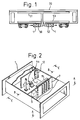
- a railway carriage 70 has a ventilation system consisting basically of an electric-powered intake blower 50 taking air in from underneath the car and leading into an intake duct 51 which typically extends along the ceiling of the car. See Fig. 1.
- the duct along the ceiling has a plurality of vents in a generally known manner. Air is exhausted from the interior space of the carriage 70 by a corresponding exhaust duct 53 which extends along the interior space near floor level.
- An electric powered exhaust blower 52 draws air from the interior space through the exhaust duct 53 and to the exterior, also underneath the carriage. Such a lay-out is generally known.
- the exterior mouths of the intake and exhaust ducts are each provided with a ventilator control device 1 which is described in more detail with reference to Figures 2 to 6.
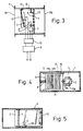
- Each control device is formed in a section of steel duct having a rectangular cross-section, mounted towards the exterior relative to the blower fan.
- the duct section has an upstream opening 101 and a downstream opening 102.
- a metal leaf spring 2 projects about three-quarters of the way across the duct, from a fixed mounting 12 at one side thereof.
- Leaf spring 2 is a rectangular sheet of springy steel e.g. cold-rolled stainless steel strip made for spring applications. It occupies most of the height of the duct, but only about three-quarters of the width (in its elongate direction).
- a stopping bar 3 and, by a bracket 4b, a limit switch unit 4 are fixed to the duct wall a short distance downstream of the leaf spring 2.
- a sufficient bending displacement of the leaf spring 2 causes it to contact a movable actuating element 4a of the limit switch unit so as to close the switch. This degree of movement also brings the leaf spring 2 up against the stopper 3 so that it cannot move further and damage itself or the switch.
- a shutter arrangement 6,7 extends right across the duct.
- This consists of a fixed shutter wall 7 which occupies the entire duct area but towards one side of the duct has a series of ventilating apertures 17 forming a grille allowing ventilating air through.
- the other element is a movable shutter plate 6 which is superimposed over the grille area of the fixed plate 7, on the upstream side, and itself has apertures 16 forming a grille corresponding to that of the fixed plate.
- the two plates therefore co-operate to form a shutter of the "hit or miss" type in which only a small length of movements of the shutter plate 6, corresponding to the pitch of the apertures, is needed to pass between the fully open and fully closed conditions.
- the apertures are parallel elongate ovals.
- the shutter plate 6 is mounted between linear bearing runners 11 at the top and bottom of the duct (see Fig. 6) to enable this movement, which is transverse to the general flow direction of the duct. A small laminar gap is left between the two plates 6,7 so that they do not make frictional contact. Where the two sets of apertures 16,17 are unmatched as seen in Fig. 4, scarcely any air can flow past the shutter. With the apertures 16,17 in register a substantial air flow is possible (indicated in Fig. 6).
- a linear solenoid 5 is fixed relative to the duct by securing it to the fixed plate 7 via a bracket 5b.
- the moving shaft 5a of the solenoid 5 is fixed to a projecting lug on the shutter plate 6 so that the solenoid 5 when actuated drives the shutter to its closed condition.
- This comprises a return spring 8 engaging between the opposite side of the duct and another lug on the shutter plate 6, which returns the shutter to the open condition when the solenoid 5 is not activated.
- Fig. 9 Basic operational conditions for the device 1 are shown schematically in Fig. 3 (Fig. 9 is more comprehensive).
- Medium voltage AC power supplied primarily to the blower motors is diverted through a transformer 9 which brings it down to the specific voltage of the solenoid 5, passing thereto via a control board 10 which links in the limit switch 4 and also has an electromagnetic contactor described later.
- the leaf spring 2 is deflected by air flowing through the ventilation duct, to a degree dependent on the air flow rate and determinable empirically. After a predetermined degree of deflection, as shown in Fig. 3, the rear surface of the leaf spring actuates the limit switch 4 which activates the linear solenoid 5. The movable plate 6 is then immediately driven to close the shutter arrangement. Because only a very short stroke S is required, the operation is very quick.
- the line P shows the characteristic of the leaf spring.
- Q indicates the rated flow rate for the ventilation system.
- R represents an excessive flow rate at which the ventilator should be shut off, to prevent pressure changes inside the car causing the "blocked ear" phenomenon.
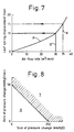
- R can be determined from empirical studies, the results of which are represented in Fig. 8.
- Fig. 8 shows how either a very large pressure change or a very fast pressure change can cause the blocked ear feeling.
- Region X is a tolerable region; region Y is a region of discomfort while the line between them represents onset of the blocked ear feeling.
- the leaf spring displacement corresponding to the shut-off air flow value R can be determined, and the limit switch placed accordingly.
- Fig. 9 is a more detailed electric system diagram for the ventilation control of one carriage.
- the circuits for controlling the intake blower and the exhaust blower are the same. Electricity is collected from an aerial cable at AC25kV using a pantograph 20 via a vacuum circuit breaker 21.
- a main transformer 22 reduces the voltage to AC440V and the motors 26,31 for the intake and exhaust blowers are powered from this.
- the motors are connected by way of circuit breakers 23 (for wiring) and also electromagnetic contactors 24 and thermal relays 25 that serve as excess current protection devices.
- Capacitors 27 are provided for starting the three-phase motors.
- Power for the linear solenoid 5 is taken from the output side of the electromagnetic contactor 24.
- a further thermal relay 29 is provided for the solenoid 5 in order to detect defects therein, and is arranged to cut off the main electromagnetic contactor 24 in the event of such a defect being detected. In this way any such defect results in power being cut off from both the solenoid 5 and also the electric blower concerned, so that the blowers do not operate, problems can be easily detected and damage minimised.
- each blower has its own leaf spring 2, limit switch 4 and solenoid 5, any problems with these can be confined to one ventilator control unit only and other control devices in other carriages need not be affected.
- Fig. 9 also reproduces the limit switch 4 and its relationship with the electromagnetic contactor 28 which actives and inactivates the solenoid 5.
- the circuit further includes a timer 30 which keeps the solenoid 5 connected to power for a predetermined time even when the limit switch 4 is no longer contacting.
- the pre-set period T1 imposed by this timer 30 should normally be at least 5 seconds, more preferably 10 to 25 seconds and most probably 15 to 20 seconds.
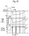
- Figure 10 shows three graphs having a common longitudinal time scale. The events are typical of those for the lead carriage of a train passing through a tunnel at very high speed e.g. about 300km/h.
- the top part of the Figure shows the pressure measured outside the carriage, and calculated for the interior by simulation for the train passing through the tunnel. Initially, the relative pressure at the outside rises to a high value of about 300mmH2O and then falls again, over a period somewhat more than 15 seconds. The exterior pressure then drops very steeply to a relative pressure below -400mmH2O. After that, it gradually returns to the normal level.
- the middle and bottom parts of the Figure illustrate the response of the ventilation control system.
- intake flow rate rises steeply and within a few seconds meets the threshold value of 35m3/min. This triggers the limit switch 4 of the intake control device and the shutter 6 on the intake promptly closes the intake duct.
- the pressure inside the carriage rises by only a very small fraction of that outside.
- the exhaust flow rate drops so that the exhaust duct is not closed but the reduced flow rate prevents any excessive pressure fall inside the carriage.
- the timer 30 of the intake device now holds the intake duct closed for the period T1: set to about 15 seconds in this case.
- the solenoid 5 is then released and the return spring 8 opens the shutter so that air flow resumes through the intake duct.
- the exterior pressure is not so extreme, so the resulting intake flow is below the threshold level T although still just above the rated flow RF. Accordingly both ducts remain open.
- the exterior pressure then drops steeply as described above. This causes a decrease in the intake flow rate, so the intake leaf spring does not actuate the shutter. There is however an immediate steep increase in the exhaust flow rate because of the low outside pressure, and the exhaust flow rate rapidly rises to the threshold value T and closes the shutter of the exhaust duct for a period T1.
- the preset closure periods T1 of the intake and exhaust devices are the same, although they need not necessarily be so.
- the solenoid 5 is deactivated and the exhaust duct is re-opened. But, the exterior pressure is still very low and the resulting full flow through the exhaust is still above the threshold level.
- the leaf spring hits the limit switch 4 again and the exhaust duct is re-closed after a short period T2 e.g. 2 to 5 seconds corresponding to the time taken for the leaf spring 2 to operate. After another 15 seconds, the "sampling" is repeated: the exhaust duct is re-opened and flow resumed but the flow rate is still too high for passenger comfort and so the duct is promptly closed again.
- T2 e.g. 2 to 5 seconds corresponding to the time taken for the leaf spring 2 to operate.
- the "sampling" is repeated: the exhaust duct is re-opened and flow resumed but the flow rate is still too high for passenger comfort and so the duct is promptly closed again.
- the co-operating relationship of the leaf spring, shutter and timer obviates any need for a purpose-made pressure sensor and processing circuitry for continuously monitoring its reading and comparing the reading with reference threshold values.
- special low-voltage DC power sources were needed to run the sensor and control unit: in the present device these are not needed.
- the leaf spring itself serves as a continuous sensor with a reference value built into its own physical construction and the spacing from the switch actuator 4a.
- the spring sensor 2 is robust, and unlike known sensing circuitry it is not liable to interference from electrical noise and the like. Using the pre-set timer feature, this simple sensor can "sample” the air flow conditions periodically while maintaining a sufficient degree of isolation of the passenger space.
- the device described is also capable, unlike the prior art devices, of coping with the extreme pressure changes caused by extremely high-speed trains.
- the leaf spring 2 is only one possibility for a flow sensing means.
- Fig. 11 shows another possibility, in which a rigid flap 2′ is mounted at a pivot 61 at the side of the duct, and moved against the restoring force of a tension spring 60 connected to a lug 62 fixed to the duct upstream of the flap 2′.
- An extra stop member 3′ is needed on the upstream side, to keep the flap perpendicular against the spring force.
- a duct was closed only if flow rate through that particular duct was sensed as excessive.
- there can be synchronous operation whereby detection of an excessive flow rate in either the intake or the exhaust duct would trigger the shutting of both said ducts.
Landscapes
- Engineering & Computer Science (AREA)
- Mechanical Engineering (AREA)
- Air-Flow Control Members (AREA)
- Air-Conditioning For Vehicles (AREA)
- Ventilation (AREA)
Applications Claiming Priority (2)
| Application Number | Priority Date | Filing Date | Title |
|---|---|---|---|
| JP17469/91 | 1991-02-08 | ||
| JP1746991 | 1991-02-08 |
Publications (2)
| Publication Number | Publication Date |
|---|---|
| EP0498554A1 EP0498554A1 (en) | 1992-08-12 |
| EP0498554B1 true EP0498554B1 (en) | 1995-01-11 |
Family
ID=11944880
Family Applications (1)
| Application Number | Title | Priority Date | Filing Date |
|---|---|---|---|
| EP92300724A Expired - Lifetime EP0498554B1 (en) | 1991-02-08 | 1992-01-28 | Methods and apparatus for ventilating carriages |
Country Status (5)
| Country | Link |
|---|---|
| US (1) | US5263894A (zh) |
| EP (1) | EP0498554B1 (zh) |
| KR (1) | KR920016297A (zh) |
| DE (1) | DE69201137T2 (zh) |
| TW (1) | TW205538B (zh) |
Families Citing this family (13)
| Publication number | Priority date | Publication date | Assignee | Title |
|---|---|---|---|---|
| JP2894104B2 (ja) * | 1992-09-09 | 1999-05-24 | 株式会社日立製作所 | 車両用換気装置及びその制御方法 |
| DE4304194C2 (de) * | 1993-02-12 | 1995-10-12 | Hagenuk Fahrzeugklima Gmbh | Verfahren und Vorrichtung zum Regulieren von Frischluftmengen in Hochgeschwindigkeitszügen |
| FR2704040B1 (fr) * | 1993-04-16 | 1995-05-19 | Gec Alsthom Transport Sa | Dispositif de suppression ou de limitation des variations brutales de pression dans les véhicules, en particulier dans les véhicules terrestres. |
| JP3254428B2 (ja) * | 1999-01-12 | 2002-02-04 | 株式会社日立製作所 | 換気装置の製作方法及び換気装置 |
| US6776451B2 (en) * | 2000-12-01 | 2004-08-17 | Alfa Leisure, Inc. | Motorhome HVAC system |
| US6807735B2 (en) | 2000-12-01 | 2004-10-26 | Alfa Leisure, Inc. | Method of fabricating a motorhome |
| US6540285B2 (en) | 2000-10-13 | 2003-04-01 | Alfa Leisure, Inc. | Motorhome with increased interior ceiling height |
| US7338109B1 (en) | 2000-10-13 | 2008-03-04 | Alfa Leisure, Inc. | Motorhome with increased interior ceiling height |
| WO2005012804A2 (en) * | 2003-07-31 | 2005-02-10 | Maxitrol Company | A method and controller for determining carbon dioxide emissions |
| JP4420637B2 (ja) * | 2003-09-03 | 2010-02-24 | 株式会社日立製作所 | 気密構体を有する高速鉄道車両用換気装置及び空調装置の運転方法 |
| CN103569145B (zh) * | 2012-08-02 | 2016-07-06 | 中车大同电力机车有限公司 | 换气系统以及电力机车 |
| US10375901B2 (en) | 2014-12-09 | 2019-08-13 | Mtd Products Inc | Blower/vacuum |
| CN110143210B (zh) * | 2019-06-06 | 2020-06-23 | 中车株洲电力机车有限公司 | 轨道车辆及其进风装置 |
Family Cites Families (6)
| Publication number | Priority date | Publication date | Assignee | Title |
|---|---|---|---|---|
| US3459114A (en) * | 1964-06-15 | 1969-08-05 | David Baclini | Blast valve |
| US3363540A (en) * | 1966-05-31 | 1968-01-16 | Navy Usa | Dynamic blast closure valve |
| US3561346A (en) * | 1969-02-26 | 1971-02-09 | Us Navy | Blast actuated module valve |
| DE3618292C3 (de) * | 1986-05-30 | 1995-12-07 | Rainer Herma | Motorisch betätigbares Druckventil für Kabinen von Eisenbahnwagen |
| DE3801891C1 (zh) * | 1988-01-23 | 1989-09-07 | Messerschmitt-Boelkow-Blohm Gmbh, 8012 Ottobrunn, De | |
| DE69122795T2 (de) * | 1990-03-19 | 1997-05-07 | Hitachi Ltd | Lüftungsausrüstung für Eisenbahnpersonenwagen und deren Anwendungsweise |
-
1992
- 1992-01-22 TW TW081100462A patent/TW205538B/zh active
- 1992-01-28 DE DE69201137T patent/DE69201137T2/de not_active Expired - Fee Related
- 1992-01-28 EP EP92300724A patent/EP0498554B1/en not_active Expired - Lifetime
- 1992-01-31 KR KR1019920001469A patent/KR920016297A/ko not_active Application Discontinuation
- 1992-02-07 US US07/832,391 patent/US5263894A/en not_active Expired - Fee Related
Also Published As
| Publication number | Publication date |
|---|---|
| TW205538B (zh) | 1993-05-11 |
| DE69201137D1 (de) | 1995-02-23 |
| US5263894A (en) | 1993-11-23 |
| EP0498554A1 (en) | 1992-08-12 |
| KR920016297A (ko) | 1992-09-24 |
| DE69201137T2 (de) | 1995-05-11 |
Similar Documents
| Publication | Publication Date | Title |
|---|---|---|
| EP0498554B1 (en) | Methods and apparatus for ventilating carriages | |
| JP2870664B2 (ja) | 自動ドアに挟まれる危険性を低減する方法及び装置 | |
| EP0824043B1 (en) | Method of monitoring the speed of a laboratory fume hood sash door | |
| JP2001518278A (ja) | 電気的に駆動されるアセンブリの動作を電気的に制御及び調節するための方法 | |
| EP0593163A1 (en) | Rolling stock ventilator and its control method | |
| US8818646B2 (en) | Method for controlling and regulating a motor-driven adjusting device | |
| JP3498400B2 (ja) | 配電盤の冷却装置 | |
| EP0541865A1 (en) | Apparatus for determining the position of a moveable structure along a track | |
| JPH08533B2 (ja) | 車両の換気方法およびその装置 | |
| JP4204659B2 (ja) | エレベータドアの動作妨害の検出方法 | |
| JPH0880850A (ja) | 車両の換気方法およびその装置 | |
| US6223467B1 (en) | Motor vehicle sensor arrangement for detecting jamming | |
| JP4776072B2 (ja) | エレベータ | |
| JP3783523B2 (ja) | エレベータ装置 | |
| US4445637A (en) | Air register with automatic zone control | |
| US7493990B2 (en) | Thermal protection of electromagnetic actuators | |
| US3531606A (en) | Switch actuating device | |
| KR101059336B1 (ko) | 공기 공급 흐름 또는 용적측정의 공기 흐름을 탐지하기위한 장치 | |
| JP2504275B2 (ja) | エレベ―タの扉装置 | |
| JP4748614B2 (ja) | エレベータの気流発生装置 | |
| EP1547958B1 (en) | Thermal protection of electromagnetic actuators | |
| JPH05278971A (ja) | エレベーターの乗かご内空調装置 | |
| JP3102780B2 (ja) | 連動扉の衝撃緩和方式 | |
| KR102147902B1 (ko) | 엘리베이터 도어용 손끼임 방지 장치 | |
| KR100224179B1 (ko) | 효소감지 센서를 이용한 차량 청결장치 |
Legal Events
| Date | Code | Title | Description |
|---|---|---|---|
| PUAI | Public reference made under article 153(3) epc to a published international application that has entered the european phase |
Free format text: ORIGINAL CODE: 0009012 |
|
| 17P | Request for examination filed |
Effective date: 19920318 |
|
| AK | Designated contracting states |
Kind code of ref document: A1 Designated state(s): DE FR GB IT |
|
| 17Q | First examination report despatched |
Effective date: 19940301 |
|
| GRAA | (expected) grant |
Free format text: ORIGINAL CODE: 0009210 |
|
| AK | Designated contracting states |
Kind code of ref document: B1 Designated state(s): DE FR GB IT |
|
| REF | Corresponds to: |
Ref document number: 69201137 Country of ref document: DE Date of ref document: 19950223 |
|
| ITF | It: translation for a ep patent filed | ||
| ET | Fr: translation filed | ||
| PLBE | No opposition filed within time limit |
Free format text: ORIGINAL CODE: 0009261 |
|
| STAA | Information on the status of an ep patent application or granted ep patent |
Free format text: STATUS: NO OPPOSITION FILED WITHIN TIME LIMIT |
|
| 26N | No opposition filed | ||
| PGFP | Annual fee paid to national office [announced via postgrant information from national office to epo] |
Ref country code: FR Payment date: 19961216 Year of fee payment: 6 |
|
| PGFP | Annual fee paid to national office [announced via postgrant information from national office to epo] |
Ref country code: GB Payment date: 19970117 Year of fee payment: 6 |
|
| PGFP | Annual fee paid to national office [announced via postgrant information from national office to epo] |
Ref country code: DE Payment date: 19970324 Year of fee payment: 6 |
|
| PG25 | Lapsed in a contracting state [announced via postgrant information from national office to epo] |
Ref country code: GB Free format text: LAPSE BECAUSE OF NON-PAYMENT OF DUE FEES Effective date: 19980128 |
|
| PG25 | Lapsed in a contracting state [announced via postgrant information from national office to epo] |
Ref country code: FR Free format text: THE PATENT HAS BEEN ANNULLED BY A DECISION OF A NATIONAL AUTHORITY Effective date: 19980131 |
|
| GBPC | Gb: european patent ceased through non-payment of renewal fee |
Effective date: 19980128 |
|
| PG25 | Lapsed in a contracting state [announced via postgrant information from national office to epo] |
Ref country code: DE Free format text: LAPSE BECAUSE OF NON-PAYMENT OF DUE FEES Effective date: 19981001 |
|
| REG | Reference to a national code |
Ref country code: FR Ref legal event code: ST |
|
| PG25 | Lapsed in a contracting state [announced via postgrant information from national office to epo] |
Ref country code: IT Free format text: LAPSE BECAUSE OF NON-PAYMENT OF DUE FEES;WARNING: LAPSES OF ITALIAN PATENTS WITH EFFECTIVE DATE BEFORE 2007 MAY HAVE OCCURRED AT ANY TIME BEFORE 2007. THE CORRECT EFFECTIVE DATE MAY BE DIFFERENT FROM THE ONE RECORDED. Effective date: 20050128 |