EP0497574A1 - Virole avec canaux de récirculation pour soufflante - Google Patents
Virole avec canaux de récirculation pour soufflante Download PDFInfo
- Publication number
- EP0497574A1 EP0497574A1 EP92300748A EP92300748A EP0497574A1 EP 0497574 A1 EP0497574 A1 EP 0497574A1 EP 92300748 A EP92300748 A EP 92300748A EP 92300748 A EP92300748 A EP 92300748A EP 0497574 A1 EP0497574 A1 EP 0497574A1
- Authority
- EP
- European Patent Office
- Prior art keywords
- flow
- rotor
- fan
- passageway
- main flow
- Prior art date
- Legal status (The legal status is an assumption and is not a legal conclusion. Google has not performed a legal analysis and makes no representation as to the accuracy of the status listed.)
- Granted
Links
- 238000011282 treatment Methods 0.000 title description 16
- 238000011144 upstream manufacturing Methods 0.000 claims abstract description 10
- 230000000740 bleeding effect Effects 0.000 claims description 2
- 230000000593 degrading effect Effects 0.000 abstract description 2
- 230000002708 enhancing effect Effects 0.000 description 4
- 238000002347 injection Methods 0.000 description 4
- 239000007924 injection Substances 0.000 description 4
- 230000002829 reductive effect Effects 0.000 description 3
- 230000002411 adverse Effects 0.000 description 2
- 238000005516 engineering process Methods 0.000 description 2
- 238000011068 loading method Methods 0.000 description 2
- 230000002441 reversible effect Effects 0.000 description 2
- 230000015556 catabolic process Effects 0.000 description 1
- 238000004891 communication Methods 0.000 description 1
- 230000006735 deficit Effects 0.000 description 1
- 230000002939 deleterious effect Effects 0.000 description 1
- 230000001627 detrimental effect Effects 0.000 description 1
- 230000000694 effects Effects 0.000 description 1
- 230000008030 elimination Effects 0.000 description 1
- 238000003379 elimination reaction Methods 0.000 description 1
- 239000012530 fluid Substances 0.000 description 1
- 230000003116 impacting effect Effects 0.000 description 1
- 238000009434 installation Methods 0.000 description 1
- 230000000670 limiting effect Effects 0.000 description 1
- 239000000463 material Substances 0.000 description 1
- 238000011089 mechanical engineering Methods 0.000 description 1
- 230000007246 mechanism Effects 0.000 description 1
- 239000002184 metal Substances 0.000 description 1
- 230000036961 partial effect Effects 0.000 description 1
- 230000003134 recirculating effect Effects 0.000 description 1
- 238000000926 separation method Methods 0.000 description 1
Images

Classifications
-
- F—MECHANICAL ENGINEERING; LIGHTING; HEATING; WEAPONS; BLASTING
- F01—MACHINES OR ENGINES IN GENERAL; ENGINE PLANTS IN GENERAL; STEAM ENGINES
- F01D—NON-POSITIVE DISPLACEMENT MACHINES OR ENGINES, e.g. STEAM TURBINES
- F01D11/00—Preventing or minimising internal leakage of working-fluid, e.g. between stages
- F01D11/08—Preventing or minimising internal leakage of working-fluid, e.g. between stages for sealing space between rotor blade tips and stator
-
- F—MECHANICAL ENGINEERING; LIGHTING; HEATING; WEAPONS; BLASTING
- F02—COMBUSTION ENGINES; HOT-GAS OR COMBUSTION-PRODUCT ENGINE PLANTS
- F02C—GAS-TURBINE PLANTS; AIR INTAKES FOR JET-PROPULSION PLANTS; CONTROLLING FUEL SUPPLY IN AIR-BREATHING JET-PROPULSION PLANTS
- F02C3/00—Gas-turbine plants characterised by the use of combustion products as the working fluid
- F02C3/14—Gas-turbine plants characterised by the use of combustion products as the working fluid characterised by the arrangement of the combustion chamber in the plant
-
- F—MECHANICAL ENGINEERING; LIGHTING; HEATING; WEAPONS; BLASTING
- F04—POSITIVE - DISPLACEMENT MACHINES FOR LIQUIDS; PUMPS FOR LIQUIDS OR ELASTIC FLUIDS
- F04D—NON-POSITIVE-DISPLACEMENT PUMPS
- F04D29/00—Details, component parts, or accessories
- F04D29/40—Casings; Connections of working fluid
- F04D29/52—Casings; Connections of working fluid for axial pumps
- F04D29/522—Casings; Connections of working fluid for axial pumps especially adapted for elastic fluid pumps
- F04D29/526—Details of the casing section radially opposing blade tips
-
- F—MECHANICAL ENGINEERING; LIGHTING; HEATING; WEAPONS; BLASTING
- F04—POSITIVE - DISPLACEMENT MACHINES FOR LIQUIDS; PUMPS FOR LIQUIDS OR ELASTIC FLUIDS
- F04D—NON-POSITIVE-DISPLACEMENT PUMPS
- F04D29/00—Details, component parts, or accessories
- F04D29/66—Combating cavitation, whirls, noise, vibration or the like; Balancing
- F04D29/68—Combating cavitation, whirls, noise, vibration or the like; Balancing by influencing boundary layers
- F04D29/681—Combating cavitation, whirls, noise, vibration or the like; Balancing by influencing boundary layers especially adapted for elastic fluid pumps
- F04D29/685—Inducing localised fluid recirculation in the stator-rotor interface
-
- F—MECHANICAL ENGINEERING; LIGHTING; HEATING; WEAPONS; BLASTING
- F04—POSITIVE - DISPLACEMENT MACHINES FOR LIQUIDS; PUMPS FOR LIQUIDS OR ELASTIC FLUIDS
- F04D—NON-POSITIVE-DISPLACEMENT PUMPS
- F04D29/00—Details, component parts, or accessories
- F04D29/26—Rotors specially for elastic fluids
- F04D29/32—Rotors specially for elastic fluids for axial flow pumps
- F04D29/321—Rotors specially for elastic fluids for axial flow pumps for axial flow compressors
-
- Y—GENERAL TAGGING OF NEW TECHNOLOGICAL DEVELOPMENTS; GENERAL TAGGING OF CROSS-SECTIONAL TECHNOLOGIES SPANNING OVER SEVERAL SECTIONS OF THE IPC; TECHNICAL SUBJECTS COVERED BY FORMER USPC CROSS-REFERENCE ART COLLECTIONS [XRACs] AND DIGESTS
- Y02—TECHNOLOGIES OR APPLICATIONS FOR MITIGATION OR ADAPTATION AGAINST CLIMATE CHANGE
- Y02T—CLIMATE CHANGE MITIGATION TECHNOLOGIES RELATED TO TRANSPORTATION
- Y02T50/00—Aeronautics or air transport
- Y02T50/60—Efficient propulsion technologies, e.g. for aircraft
-
- Y—GENERAL TAGGING OF NEW TECHNOLOGICAL DEVELOPMENTS; GENERAL TAGGING OF CROSS-SECTIONAL TECHNOLOGIES SPANNING OVER SEVERAL SECTIONS OF THE IPC; TECHNICAL SUBJECTS COVERED BY FORMER USPC CROSS-REFERENCE ART COLLECTIONS [XRACs] AND DIGESTS
- Y10—TECHNICAL SUBJECTS COVERED BY FORMER USPC
- Y10S—TECHNICAL SUBJECTS COVERED BY FORMER USPC CROSS-REFERENCE ART COLLECTIONS [XRACs] AND DIGESTS
- Y10S415/00—Rotary kinetic fluid motors or pumps
- Y10S415/914—Device to control boundary layer
Definitions
- This invention relates to gas turbine engines and more particularly to means for enhancing stall margin of the fan without adversely impacting efficiency by incorporating a treatment to the case of the fan.
- surge or stall is a phenomenon that is characteristic to all types of axial flow fans and compressors and occurs at a given engine operating condition and that if gone unattended could be deleterious or harmful to not only the engine's performance but to the engine itself.
- rotating stall is a phenomenon that occurs whenever sufficient blades or regions of the blades stall so as to occasion a complete blockage or reversal of flow of air through the fan and/or compressor. Also flow separation on the airfoils can lead to compressor stall or rotation stall which, in turn, can lead to an overall system breakdown of the flow, i.e., surge.
- surge can ensue.
- surge problem can be corrected by either providing means for handling an incipient surge or designing the engine so that the engine never operates where a stall can manifest.
- an incipient stall may be corrected simply by reducing engine power as compared to designing the engine so that its operating parameters assure that the engine always operates below a given stall line.
- surge may manifest in many different forms and stall may occur in one or more blades and at different regions. The most limiting stall characteristics often occur at the tip of the blade which essentially is the type of stall being addressed by this invention.
- this invention is directed to enhance the stall line so as to avoid the manifestation of an incipient stall. This will serve to prevent compressor stall although it will be understood that the treatment of the casing does not affect whether or not a rotating stall could degenerate into a surge condition.
- U.S. Patent 3,580,692 teaches a honeycomb structure casing treatment for enhancing the stall characteristics.
- rotating stall is a mass of cells of stalled and highly turbulent air that precesses around the rotor at a rate that is nearly half the rotating speed of the rotor and extends upstream of the rotor a significant axial distance
- rotating stall extends a significant distance upstream of the rotor and since it is a collection of a large mass of stalled air cells, a significantly large recess would be necessary in order to swallow the rotating stall.
- An object of this invention is to enhance stall margin of a fan of a gas turbine engine by an improved case treatment.
- a gas turbine engine having a fan rotor and means encasing the fan rotor for defining a main flow stream, a passageway in said encasing means having an inlet passage located downstream of the leading edge of the fan blade of said fan rotor for bleeding low momentum flow relative to the rotor from the main flow into said passageway and an outlet located at a point upstream of said inlet passage for returning said removed flow to said main flow at a velocity that is higher than the velocity of the flow in said inlet passage, anti-swirl vanes in said passageway for straightening or reversing the swirl of the low momentum flow, said passage flow being arranged to be no greater than eight percentage points of the total flow in said main flow, and said inlet passage being oriented with respect to the main flow to selectively remove from the main flow low momentum flow relative to the rotor that has low axial velocity but high absolute tangential velocity so that the strong rotor relative flow that has high axial velocity is discouraged from being recirculated in
- a feature of this invention is to provide an improved case treatment for separating low rotor relative momentum flow which has mostly a high swirl component in the absolute frame out of the main flow path and reintroducing the flow into the flow path at a higher velocity with the elimination or even reversal of the swirl component.
- the injected flow is preferably to be oriented at the mean rotor blade tip angle at the point of injection to result in minimal disturbance to the freestream flow inboard of the casing.
- a further feature of this invention is the removal of low rotor relative momentum flow adjacent the casing of the fan rotor and reintroducing the flow back into the mainstream upstream from the removal juncture, where the amount of removed flow is no greater than 8% of the main flow in the fan.
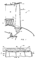
- Fig. 1 is a partial view in schematic illustrating the invention as applied to the casing of a fan of a fan jet engine of the type powering aircraft.
- Fig. 2 is an enlarged view showing the casing treatment of Fig. 1 in schematic to illustrate the flow pattern.
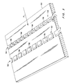
- Fig. 3 is a view in perspective showing one embodiment of a case treatment incorporating the invention.
- Fig. 4 is a perspective view showing the top surface of the structure of Fig. 3.
- this invention constitutes an improvement over the axially skewed slots disclosed in U.S. Patent No. 4,239,452, supra. It is noted that the embodiment disclosed in this patent application is directed toward the shroud that surrounds the fan of a fan jet engine, it being understood that the same principle disclosed by this concept may be equally applied to the hub supporting the fan within the scope of the invention.
- Figs. 1 and 2 the fan rotor generally illustrated by reference numeral 10 is attached to shaft 12 and is mounted on the front end of the engine and is surrounded by engine case 14.
- the fan rotor consisting of hub 16 and a plurality of axial flow fan blades 18 (one being shown) extending radially and in close proximity to the inner diameter surface of case 14.
- the case 14 may carry a shroud 20 fabricated from a suitable material to form a rub strip which serves as an outer air seal for the tips of the blades 18.
- Air flow out of the fan is split by splitter 19 where a portion flows into the engine case 21 and the remaining portion flows through the fan duct 22.
- splitter 19 Details of such engines can be had by referring to the PW4000, JT9D and F100 family of engines which are manufactured by Pratt & Whitney, a division of United Technologies Corporation, the applicant in this patent application.
- this invention is concerned with the treatment of the fan case for enhancing stall margin and is generally shown by reference numeral 26.
- a more detailed configuration is shown in Fig. 2 which shows the side profile of the tip portion of blade 18 in proximity to the case treatment 26.
- the enlarged arrow A depicts the direction of flow into the fan.
- Discrete passageways in the rub strip are designed to capture only the low rotor relative momentum flow, efficiently remove and sometimes reverse the swirl component, accelerate it, and reintroduce it into the fan flow stream in a nearly axial direction that is closely aligned with the fan rotor blade mean tip metal angle at the point of injection to result in minimal disturbance to the freestream flow inboard of the casing.
- the curvature of these passages is designed to recirculate the air as efficiently as possible and to assure the proper reintroduction of air into the fan blade stream.
- the fan air adjacent the tip is removed at some location downstream of the leading edge 32 of blade 18 through passage 34 and reintroduced at a location upstream of passageway 34 through passage 36.
- the injection position can be upstream of the rotor leading edge.
- a plurality of turning vanes 38 are circumferentially mounted intermediate passages 34 and 36.
- the forward facing wall formed in passage 34 is judiciously angled so that the weak axial flow near the casing, which can eventually stall the component, is selectively recirculated and injected back into the fan air stream at high velocity while strong axial flow tends to remain in the gas path and is not recirculated. This tends to avoid recirculating air more than once which can be detrimental to component efficiency. While the particular passage configurations and dimensions will be primarily dictated by the particular application to which this invention is utilized, it is critical that the amount of flow removed from the fan stream does not exceed 8% of the total flow into the fan.
- Figs. 3 and 4 exemplifies an integral case treatment that may be adapted as a retrofit where it is desirable to modify an existing case.
- a unit formed in accordance with this design can simply be inserted into a recess formed in the inner surface of an already existing case.
- the passageways are formed in a ring-like element 50 having a pair of banks 52 and 54 of circumferentially spaced passageways 56 and 58 respectively which are shown as rectangular in shape.
- Fig. 3 is a view of the inner surface of ring-like element 50 facing the tips of the blade.
- the first bank 52 of passageways 56 is located to be in communication with the flow downstream of the leading edge of the fan blade and the second bank 54 of passageways 58.
- the back surface or outer diameter of ring-like element 50 as shown in Fig. 4 forms annular cavities 60 and 62 adjacent the passageways 56 and 58 respectively for collecting the flow and redistributing it back into the main flow stream.
- a plurality of vanes 66 are circumferentially disposed between the banks 52 and 54 of passageways 56 and 58, respectively, and are suitably located so as to eliminate or even reverse the swirl component of the induced air.
- the passageways 56 and 58 and space 68 between vanes 66 are so dimensioned to accelerate the induced air prior to being reintroduced back into the main fan airstream.
- the distance between banks of passageways 56 and 58 and the specific location relative to the axial extent of the blades is predicated on the particular application where the invention is being employed.
- the injection ports 58 can be positioned from somewhat upstream of the rotor leading edge, to downstream of the leading edge and the intake ports 56 must be downstream of the leading edge.
- a test conducted to compare the effect of case treatment incorporating this invention with smooth wall surface and axial skewed grooves by simulating the aircraft installation of a commercial transport fan jet engine produced the following results.
- the case incorporating the invention disclosed in Figs. 3 and 4 showed a 21 percentage points improvement of stall margin over a smooth wall casing and a 10 percentage points improvement over the axial skewed grooves.
- the efficiency of the case treatment utilizing this invention exhibited one percentage point higher than the efficiency of the axial skewed grooves, and demonstrated the same efficiency as with a smooth wall.
Landscapes
- Engineering & Computer Science (AREA)
- Mechanical Engineering (AREA)
- General Engineering & Computer Science (AREA)
- Chemical & Material Sciences (AREA)
- Combustion & Propulsion (AREA)
- Structures Of Non-Positive Displacement Pumps (AREA)
Applications Claiming Priority (2)
| Application Number | Priority Date | Filing Date | Title |
|---|---|---|---|
| US64849991A | 1991-01-30 | 1991-01-30 | |
| US648499 | 1991-01-30 |
Publications (2)
| Publication Number | Publication Date |
|---|---|
| EP0497574A1 true EP0497574A1 (fr) | 1992-08-05 |
| EP0497574B1 EP0497574B1 (fr) | 1995-09-20 |
Family
ID=24601038
Family Applications (1)
| Application Number | Title | Priority Date | Filing Date |
|---|---|---|---|
| EP92300748A Expired - Lifetime EP0497574B1 (fr) | 1991-01-30 | 1992-01-29 | Virole avec canaux de récirculation pour soufflante |
Country Status (5)
| Country | Link |
|---|---|
| US (1) | US5308225A (fr) |
| EP (1) | EP0497574B1 (fr) |
| JP (1) | JP3212341B2 (fr) |
| KR (1) | KR100198721B1 (fr) |
| DE (1) | DE69204861T2 (fr) |
Cited By (27)
| Publication number | Priority date | Publication date | Assignee | Title |
|---|---|---|---|---|
| WO1995010692A1 (fr) * | 1993-10-15 | 1995-04-20 | United Technologies Corporation | Derivation active du flux aux extremites dans un passage de redresseur a aubes |
| WO1995018922A1 (fr) * | 1994-01-07 | 1995-07-13 | British Technology Group Limited | Enveloppes pour ventilateurs a ecoulement axial |
| EP0718469A1 (fr) * | 1994-12-23 | 1996-06-26 | United Technologies Corporation | Moyeu du roteur du compresseur |
| EP0719908A1 (fr) * | 1994-12-29 | 1996-07-03 | United Technologies Corporation | Virole avec canaux de récirculation pour compresseur |
| EP0719907A1 (fr) * | 1994-12-29 | 1996-07-03 | United Technologies Corporation | Virole pour turbine à gaz |
| EP0751280A1 (fr) * | 1995-05-31 | 1997-01-02 | United Technologies Corporation | Paroi avec plenum pour l'alignement de l'écoulement dans les aubes de compresseur |
| EP0992656A1 (fr) * | 1998-10-05 | 2000-04-12 | Asea Brown Boveri AG | Turbomachine pour comprimer ou détendre un fluide comprimable |
| EP1277967A1 (fr) * | 2001-07-18 | 2003-01-22 | MTU Aero Engines GmbH | Structure de boítier de compresseur |
| EP1052376A3 (fr) * | 1999-05-10 | 2003-06-04 | General Electric Company | Méthode d'étanchéité pour les extrémités des aubes de compresseurs |
| EP1659293A3 (fr) * | 2004-11-17 | 2006-12-20 | Rolls-Royce Deutschland Ltd & Co KG | Turbomachine |
| WO2008011864A1 (fr) * | 2006-07-26 | 2008-01-31 | Mtu Aero Engines Gmbh | Turbine à gaz dotée d'un segment annulaire comprenant un canal de recirculation |
| EP1536146A3 (fr) * | 2003-11-26 | 2008-04-02 | Rolls-Royce Deutschland Ltd & Co KG | Turbomachine et prélèvement de fluide |
| EP2151582A2 (fr) | 2008-08-08 | 2010-02-10 | Rolls-Royce Deutschland Ltd & Co KG | Machine de traitement des écoulements |
| CN102562666A (zh) * | 2012-01-06 | 2012-07-11 | 北京航空航天大学 | 一种非定常驻涡式处理机匣 |
| US8251648B2 (en) | 2008-02-28 | 2012-08-28 | Rolls-Royce Deutschland Ltd & Co Kg | Casing treatment for axial compressors in a hub area |
| US8257022B2 (en) | 2008-07-07 | 2012-09-04 | Rolls-Royce Deutschland Ltd Co KG | Fluid flow machine featuring a groove on a running gap of a blade end |
| US8419355B2 (en) | 2007-08-10 | 2013-04-16 | Rolls-Royce Deutschland Ltd & Co Kg | Fluid flow machine featuring an annulus duct wall recess |
| CN103967843A (zh) * | 2013-02-04 | 2014-08-06 | 中国科学院工程热物理研究所 | 压气机周向槽自循环喷气组合式扩稳装置及方法 |
| US8834116B2 (en) | 2008-10-21 | 2014-09-16 | Rolls-Royce Deutschland Ltd & Co Kg | Fluid flow machine with peripheral energization near the suction side |
| EP2808558A1 (fr) | 2013-05-31 | 2014-12-03 | Rolls-Royce Deutschland Ltd & Co KG | Ensemble structurel pour une turbomachine |
| EP2808556A1 (fr) | 2013-05-31 | 2014-12-03 | Rolls-Royce Deutschland Ltd & Co KG | Ensemble structurel pour une turbomachine |
| EP2808559A1 (fr) | 2013-05-31 | 2014-12-03 | Rolls-Royce Deutschland Ltd & Co KG | Ensemble structurel pour une turbomachine |
| EP2808557A1 (fr) | 2013-05-31 | 2014-12-03 | Rolls-Royce Deutschland Ltd & Co KG | Ensemble structurel pour une turbomachine |
| EP2110559A3 (fr) * | 2008-04-18 | 2015-03-25 | Rolls-Royce Deutschland Ltd & Co KG | Turbomachine avec réinjection de fluide pour influencer la couche limite |
| US9115594B2 (en) | 2010-12-28 | 2015-08-25 | Rolls-Royce Corporation | Compressor casing treatment for gas turbine engine |
| US9885368B2 (en) | 2012-05-24 | 2018-02-06 | Carrier Corporation | Stall margin enhancement of axial fan with rotating shroud |
| WO2019102231A1 (fr) * | 2017-11-27 | 2019-05-31 | University Of Leicester | Ensemble d'écoulement pour turbomachine axiale |
Families Citing this family (64)
| Publication number | Priority date | Publication date | Assignee | Title |
|---|---|---|---|---|
| US6244817B1 (en) * | 1996-12-05 | 2001-06-12 | Mcdonnell Douglas Corporation | Method and apparatus for a fan noise controller |
| US6164911A (en) * | 1998-11-13 | 2000-12-26 | Pratt & Whitney Canada Corp. | Low aspect ratio compressor casing treatment |
| US6231301B1 (en) | 1998-12-10 | 2001-05-15 | United Technologies Corporation | Casing treatment for a fluid compressor |
| US6379110B1 (en) * | 1999-02-25 | 2002-04-30 | United Technologies Corporation | Passively driven acoustic jet controlling boundary layers |
| US6290458B1 (en) | 1999-09-20 | 2001-09-18 | Hitachi, Ltd. | Turbo machines |
| GB2373023B (en) * | 2001-03-05 | 2004-12-22 | Rolls Royce Plc | Tip treatment bar components |
| US6585479B2 (en) * | 2001-08-14 | 2003-07-01 | United Technologies Corporation | Casing treatment for compressors |
| WO2003072910A1 (fr) * | 2002-02-28 | 2003-09-04 | Mtu Aero Engines Gmbh | Structure de recirculation de turbocompresseurs |
| AU2003207365A1 (en) * | 2002-02-28 | 2003-09-09 | Daimlerchrysler Ag | Anti-stall tip treatment means for turbo-compressors |
| DE10218459B3 (de) * | 2002-04-25 | 2004-01-15 | Mtu Aero Engines Gmbh | Verdichter in mehrstufiger Axialbauart |
| US7186072B2 (en) * | 2002-08-23 | 2007-03-06 | Mtu Aero Engines Gmbh | Recirculation structure for a turbocompressor |
| US7074006B1 (en) * | 2002-10-08 | 2006-07-11 | The United States Of America As Represented By The Administrator Of National Aeronautics And Space Administration | Endwall treatment and method for gas turbine |
| DE10355241A1 (de) | 2003-11-26 | 2005-06-30 | Rolls-Royce Deutschland Ltd & Co Kg | Strömungsarbeitsmaschine mit Fluidzufuhr |
| US7147426B2 (en) * | 2004-05-07 | 2006-12-12 | Pratt & Whitney Canada Corp. | Shockwave-induced boundary layer bleed |
| DE102004030597A1 (de) | 2004-06-24 | 2006-01-26 | Rolls-Royce Deutschland Ltd & Co Kg | Strömungsarbeitsmaschine mit Aussenradstrahlerzeugung am Stator |
| DE102004043036A1 (de) | 2004-09-06 | 2006-03-09 | Rolls-Royce Deutschland Ltd & Co Kg | Strömungsarbeitsmaschine mit Fluidentnahme |
| US7553122B2 (en) * | 2005-12-22 | 2009-06-30 | General Electric Company | Self-aspirated flow control system for centrifugal compressors |
| US7475539B2 (en) * | 2006-05-24 | 2009-01-13 | Honeywell International, Inc. | Inclined rib ported shroud compressor housing |
| US20080044273A1 (en) * | 2006-08-15 | 2008-02-21 | Syed Arif Khalid | Turbomachine with reduced leakage penalties in pressure change and efficiency |
| US8038388B2 (en) * | 2007-03-05 | 2011-10-18 | United Technologies Corporation | Abradable component for a gas turbine engine |
| US8082726B2 (en) * | 2007-06-26 | 2011-12-27 | United Technologies Corporation | Tangential anti-swirl air supply |
| US8272832B2 (en) * | 2008-04-17 | 2012-09-25 | Honeywell International Inc. | Centrifugal compressor with surge control, and associated method |
| US8052375B2 (en) * | 2008-06-02 | 2011-11-08 | General Electric Company | Fluidic sealing for turbomachinery |
| US8337146B2 (en) * | 2009-06-03 | 2012-12-25 | Pratt & Whitney Canada Corp. | Rotor casing treatment with recessed baffles |
| DE102009032841A1 (de) * | 2009-07-13 | 2011-01-20 | Rolls-Royce Deutschland Ltd & Co Kg | Geräuschreduziertes Flugzeugtriebwerk sowie Verfahren zur Verminderung von Geräuschemissionen eines Flugzeugtriebwerks |
| FR2949518B1 (fr) * | 2009-08-31 | 2011-10-21 | Snecma | Compresseur de turbomachine ayant des injecteurs d'air |
| US8540482B2 (en) | 2010-06-07 | 2013-09-24 | United Technologies Corporation | Rotor assembly for gas turbine engine |
| US8602720B2 (en) | 2010-06-22 | 2013-12-10 | Honeywell International Inc. | Compressors with casing treatments in gas turbine engines |
| EP2532898A1 (fr) * | 2011-06-08 | 2012-12-12 | Siemens Aktiengesellschaft | Turbocompresseur axial |
| CN102852668B (zh) * | 2011-06-29 | 2015-08-12 | 中国科学院工程热物理研究所 | 一种轴流风扇/压气机自引气喷气机构 |
| US9062558B2 (en) * | 2011-07-15 | 2015-06-23 | United Technologies Corporation | Blade outer air seal having partial coating |
| DE102011107523B4 (de) * | 2011-07-15 | 2016-08-11 | MTU Aero Engines AG | System zum Einblasen eines Fluids, Verdichter sowie Turbomaschine |
| US9995165B2 (en) | 2011-07-15 | 2018-06-12 | United Technologies Corporation | Blade outer air seal having partial coating |
| CN103133413A (zh) * | 2011-11-25 | 2013-06-05 | 中国航空工业集团公司沈阳发动机设计研究所 | 一种发动机风扇多层机匣结构 |
| JP5567077B2 (ja) * | 2012-08-23 | 2014-08-06 | 三菱重工業株式会社 | 回転機械 |
| US10018061B2 (en) | 2013-03-12 | 2018-07-10 | United Technologies Corporation | Vane tip machining fixture assembly |
| US9726185B2 (en) | 2013-05-14 | 2017-08-08 | Honeywell International Inc. | Centrifugal compressor with casing treatment for surge control |
| DE102013219818B3 (de) * | 2013-09-30 | 2015-02-05 | Deutsches Zentrum für Luft- und Raumfahrt e.V. | Axialverdichter |
| JP6131177B2 (ja) * | 2013-12-03 | 2017-05-17 | 三菱重工業株式会社 | シール構造、及び回転機械 |
| FR3015593B1 (fr) * | 2013-12-20 | 2018-09-07 | Safran Aircraft Engines | Carter en materiau composite a matrice organique favorisant l'evacuation des fumees |
| US10036263B2 (en) | 2014-10-22 | 2018-07-31 | United Technologies Corporation | Stator assembly with pad interface for a gas turbine engine |
| CN104405685A (zh) * | 2014-11-20 | 2015-03-11 | 哈尔滨广瀚燃气轮机有限公司 | 一种改善压气机性能用自循环与周向槽混合式处理机匣 |
| CN104675755B (zh) * | 2015-01-14 | 2017-03-29 | 西北工业大学 | 轴流压气机周向错位型自流通机匣处理方法 |
| US9932985B2 (en) * | 2015-02-03 | 2018-04-03 | Honeywell International Inc. | Gas turbine engine compressors having optimized stall enhancement feature configurations and methods for the production thereof |
| US10107307B2 (en) * | 2015-04-14 | 2018-10-23 | Pratt & Whitney Canada Corp. | Gas turbine engine rotor casing treatment |
| DE102016118369A1 (de) | 2016-09-28 | 2018-03-29 | Ebm-Papst Mulfingen Gmbh & Co. Kg | Ansaugdüse und Ausblaseinheit eines Ventilators |
| US10683076B2 (en) | 2017-10-31 | 2020-06-16 | Coflow Jet, LLC | Fluid systems that include a co-flow jet |
| US11293293B2 (en) * | 2018-01-22 | 2022-04-05 | Coflow Jet, LLC | Turbomachines that include a casing treatment |
| US10830102B2 (en) | 2018-03-01 | 2020-11-10 | General Electric Company | Casing with tunable lattice structure |
| TWI671470B (zh) * | 2018-05-04 | 2019-09-11 | 奇鋐科技股份有限公司 | 風扇降噪結構 |
| CN112855625B (zh) * | 2018-05-10 | 2022-12-02 | 奇鋐科技股份有限公司 | 风扇降噪结构 |
| US11326624B2 (en) | 2018-05-15 | 2022-05-10 | Asia Vital Components Co., Ltd. | Fan noise-lowering structure |
| US11326623B2 (en) | 2018-05-15 | 2022-05-10 | Asia Vital Components Co., Ltd. | Fan noise-lowering structure |
| US10914318B2 (en) | 2019-01-10 | 2021-02-09 | General Electric Company | Engine casing treatment for reducing circumferentially variable distortion |
| US11047249B2 (en) * | 2019-05-01 | 2021-06-29 | Raytheon Technologies Corporation | Labyrinth seal with passive check valve |
| GB2600584B (en) | 2019-07-23 | 2024-03-06 | Coflow Jet Llc | Fluid systems and methods that address flow separation |
| BE1028335B1 (fr) * | 2020-05-20 | 2021-12-20 | Safran Aero Boosters | Sous-ensemble de compresseur basse pression d'une turbomachine d'aéronef |
| CN111734685B (zh) * | 2020-07-07 | 2021-11-02 | 江西乐富军工装备有限公司 | 一种通风换气装置 |
| US20230184125A1 (en) * | 2021-12-15 | 2023-06-15 | General Electric Company | Engine component with abradable material and treatment |
| US11702945B2 (en) | 2021-12-22 | 2023-07-18 | Rolls-Royce North American Technologies Inc. | Turbine engine fan case with tip injection air recirculation passage |
| US11946379B2 (en) * | 2021-12-22 | 2024-04-02 | Rolls-Royce North American Technologies Inc. | Turbine engine fan case with manifolded tip injection air recirculation passages |
| US11732612B2 (en) | 2021-12-22 | 2023-08-22 | Rolls-Royce North American Technologies Inc. | Turbine engine fan track liner with tip injection air recirculation passage |
| CN114321014A (zh) * | 2021-12-24 | 2022-04-12 | 中国科学院工程热物理研究所 | 一种离心压气机径向扩压器局部自循环流动控制结构 |
| CN114838002B (zh) * | 2022-04-23 | 2024-01-30 | 西北工业大学 | 一种自循环机匣的扩稳处理装置 |
Citations (5)
| Publication number | Priority date | Publication date | Assignee | Title |
|---|---|---|---|---|
| GB504214A (en) * | 1937-02-24 | 1939-04-21 | Rheinmetall Borsig Ag Werk Bor | Improvements in and relating to turbo compressors |
| GB825967A (en) * | 1956-03-28 | 1959-12-23 | Robert Jean Pouit | Improvements in turbines and in particular gas turbines |
| FR2325830A1 (fr) * | 1975-09-25 | 1977-04-22 | Rolls Royce | Perfectionnements aux carters de compresseurs de moteurs a turbine a gaz |
| GB2017228A (en) * | 1977-07-14 | 1979-10-03 | Pratt & Witney Aircraft Of Can | Shroud for a turbine rotor |
| WO1985000640A1 (fr) * | 1983-07-28 | 1985-02-14 | Nordisk Ventilator Co. A/S | Soufflante a ecoulement axial |
Family Cites Families (9)
| Publication number | Priority date | Publication date | Assignee | Title |
|---|---|---|---|---|
| US948692A (en) * | 1910-02-08 | Willis G Dodd | Rotary engine. | |
| US743883A (en) * | 1903-07-30 | 1903-11-10 | Morgan D Kalbach | Rotary engine. |
| US1349487A (en) * | 1917-05-31 | 1920-08-10 | Erastus S Bennett | Turbine-engine |
| US2709917A (en) * | 1952-02-15 | 1955-06-07 | United Aircraft Corp | Transonic flow control |
| JPS5211405A (en) * | 1975-07-17 | 1977-01-28 | Mitsubishi Heavy Ind Ltd | Pump with inducer |
| US4212585A (en) * | 1978-01-20 | 1980-07-15 | Northern Research And Engineering Corporation | Centrifugal compressor |
| US4375937A (en) * | 1981-01-28 | 1983-03-08 | Ingersoll-Rand Company | Roto-dynamic pump with a backflow recirculator |
| DE3539604C1 (de) * | 1985-11-08 | 1987-02-19 | Turbo Lufttechnik Gmbh | Axialgeblaese |
| CH675279A5 (fr) * | 1988-06-29 | 1990-09-14 | Asea Brown Boveri |
-
1992
- 1992-01-29 KR KR1019920001306A patent/KR100198721B1/ko not_active IP Right Cessation
- 1992-01-29 DE DE69204861T patent/DE69204861T2/de not_active Expired - Lifetime
- 1992-01-29 EP EP92300748A patent/EP0497574B1/fr not_active Expired - Lifetime
- 1992-01-30 JP JP04015892A patent/JP3212341B2/ja not_active Expired - Fee Related
- 1992-07-28 US US07/925,312 patent/US5308225A/en not_active Expired - Lifetime
Patent Citations (5)
| Publication number | Priority date | Publication date | Assignee | Title |
|---|---|---|---|---|
| GB504214A (en) * | 1937-02-24 | 1939-04-21 | Rheinmetall Borsig Ag Werk Bor | Improvements in and relating to turbo compressors |
| GB825967A (en) * | 1956-03-28 | 1959-12-23 | Robert Jean Pouit | Improvements in turbines and in particular gas turbines |
| FR2325830A1 (fr) * | 1975-09-25 | 1977-04-22 | Rolls Royce | Perfectionnements aux carters de compresseurs de moteurs a turbine a gaz |
| GB2017228A (en) * | 1977-07-14 | 1979-10-03 | Pratt & Witney Aircraft Of Can | Shroud for a turbine rotor |
| WO1985000640A1 (fr) * | 1983-07-28 | 1985-02-14 | Nordisk Ventilator Co. A/S | Soufflante a ecoulement axial |
Cited By (41)
| Publication number | Priority date | Publication date | Assignee | Title |
|---|---|---|---|---|
| WO1995010692A1 (fr) * | 1993-10-15 | 1995-04-20 | United Technologies Corporation | Derivation active du flux aux extremites dans un passage de redresseur a aubes |
| US5431533A (en) * | 1993-10-15 | 1995-07-11 | United Technologies Corporation | Active vaned passage casing treatment |
| WO1995018922A1 (fr) * | 1994-01-07 | 1995-07-13 | British Technology Group Limited | Enveloppes pour ventilateurs a ecoulement axial |
| EP0718469A1 (fr) * | 1994-12-23 | 1996-06-26 | United Technologies Corporation | Moyeu du roteur du compresseur |
| EP0719908A1 (fr) * | 1994-12-29 | 1996-07-03 | United Technologies Corporation | Virole avec canaux de récirculation pour compresseur |
| EP0719907A1 (fr) * | 1994-12-29 | 1996-07-03 | United Technologies Corporation | Virole pour turbine à gaz |
| EP0751280A1 (fr) * | 1995-05-31 | 1997-01-02 | United Technologies Corporation | Paroi avec plenum pour l'alignement de l'écoulement dans les aubes de compresseur |
| US6264425B1 (en) | 1998-10-05 | 2001-07-24 | Asea Brown Boveri Ag | Fluid-flow machine for compressing or expanding a compressible medium |
| EP0992656A1 (fr) * | 1998-10-05 | 2000-04-12 | Asea Brown Boveri AG | Turbomachine pour comprimer ou détendre un fluide comprimable |
| EP1052376A3 (fr) * | 1999-05-10 | 2003-06-04 | General Electric Company | Méthode d'étanchéité pour les extrémités des aubes de compresseurs |
| EP1277967A1 (fr) * | 2001-07-18 | 2003-01-22 | MTU Aero Engines GmbH | Structure de boítier de compresseur |
| US6742983B2 (en) | 2001-07-18 | 2004-06-01 | Mtu Aero Engines Gmbh | Compressor casing structure |
| EP1536146A3 (fr) * | 2003-11-26 | 2008-04-02 | Rolls-Royce Deutschland Ltd & Co KG | Turbomachine et prélèvement de fluide |
| EP1659293A3 (fr) * | 2004-11-17 | 2006-12-20 | Rolls-Royce Deutschland Ltd & Co KG | Turbomachine |
| WO2008011864A1 (fr) * | 2006-07-26 | 2008-01-31 | Mtu Aero Engines Gmbh | Turbine à gaz dotée d'un segment annulaire comprenant un canal de recirculation |
| US8092148B2 (en) | 2006-07-26 | 2012-01-10 | Mtu Aero Engines Gmbh | Gas turbine having a peripheral ring segment including a recirculation channel |
| US8419355B2 (en) | 2007-08-10 | 2013-04-16 | Rolls-Royce Deutschland Ltd & Co Kg | Fluid flow machine featuring an annulus duct wall recess |
| US8251648B2 (en) | 2008-02-28 | 2012-08-28 | Rolls-Royce Deutschland Ltd & Co Kg | Casing treatment for axial compressors in a hub area |
| EP2110559A3 (fr) * | 2008-04-18 | 2015-03-25 | Rolls-Royce Deutschland Ltd & Co KG | Turbomachine avec réinjection de fluide pour influencer la couche limite |
| US8257022B2 (en) | 2008-07-07 | 2012-09-04 | Rolls-Royce Deutschland Ltd Co KG | Fluid flow machine featuring a groove on a running gap of a blade end |
| US8382422B2 (en) | 2008-08-08 | 2013-02-26 | Rolls-Royce Deutschland Ltd & Co Kg | Fluid flow machine |
| DE102008037154A1 (de) | 2008-08-08 | 2010-02-11 | Rolls-Royce Deutschland Ltd & Co Kg | Strömungsarbeitsmaschine |
| EP2151582A2 (fr) | 2008-08-08 | 2010-02-10 | Rolls-Royce Deutschland Ltd & Co KG | Machine de traitement des écoulements |
| US8834116B2 (en) | 2008-10-21 | 2014-09-16 | Rolls-Royce Deutschland Ltd & Co Kg | Fluid flow machine with peripheral energization near the suction side |
| US9115594B2 (en) | 2010-12-28 | 2015-08-25 | Rolls-Royce Corporation | Compressor casing treatment for gas turbine engine |
| CN102562666A (zh) * | 2012-01-06 | 2012-07-11 | 北京航空航天大学 | 一种非定常驻涡式处理机匣 |
| US9885368B2 (en) | 2012-05-24 | 2018-02-06 | Carrier Corporation | Stall margin enhancement of axial fan with rotating shroud |
| CN103967843A (zh) * | 2013-02-04 | 2014-08-06 | 中国科学院工程热物理研究所 | 压气机周向槽自循环喷气组合式扩稳装置及方法 |
| DE102013210169A1 (de) | 2013-05-31 | 2014-12-04 | Rolls-Royce Deutschland Ltd & Co Kg | Strukturbaugruppe für eine Strömungsmaschine |
| DE102013210167A1 (de) | 2013-05-31 | 2014-12-04 | Rolls-Royce Deutschland Ltd & Co Kg | Strukturbaugruppe für eine Strömungsmaschine |
| EP2808557A1 (fr) | 2013-05-31 | 2014-12-03 | Rolls-Royce Deutschland Ltd & Co KG | Ensemble structurel pour une turbomachine |
| DE102013210171A1 (de) | 2013-05-31 | 2014-12-04 | Rolls-Royce Deutschland Ltd & Co Kg | Strukturbaugruppe für eine Strömungsmaschine |
| DE102013210168A1 (de) | 2013-05-31 | 2014-12-04 | Rolls-Royce Deutschland Ltd & Co Kg | Strukturbaugruppe für eine Strömungsmaschine |
| EP2808559A1 (fr) | 2013-05-31 | 2014-12-03 | Rolls-Royce Deutschland Ltd & Co KG | Ensemble structurel pour une turbomachine |
| EP2808556A1 (fr) | 2013-05-31 | 2014-12-03 | Rolls-Royce Deutschland Ltd & Co KG | Ensemble structurel pour une turbomachine |
| US9587509B2 (en) | 2013-05-31 | 2017-03-07 | Rolls-Royce Deutschland Ltd & Co Kg | Assembly for a fluid flow machine |
| US9664204B2 (en) | 2013-05-31 | 2017-05-30 | Rolls-Royce Deutschland Ltd & Co Kg | Assembly for a fluid flow machine |
| US9822792B2 (en) | 2013-05-31 | 2017-11-21 | Rolls-Royce Deutschland Ltd & Co Kg | Assembly for a fluid flow machine |
| EP2808558A1 (fr) | 2013-05-31 | 2014-12-03 | Rolls-Royce Deutschland Ltd & Co KG | Ensemble structurel pour une turbomachine |
| US10006467B2 (en) | 2013-05-31 | 2018-06-26 | Rolls-Royce Deutschland Ltd & Co Kg | Assembly for a fluid flow machine |
| WO2019102231A1 (fr) * | 2017-11-27 | 2019-05-31 | University Of Leicester | Ensemble d'écoulement pour turbomachine axiale |
Also Published As
| Publication number | Publication date |
|---|---|
| JPH04314931A (ja) | 1992-11-06 |
| KR920015020A (ko) | 1992-08-26 |
| DE69204861D1 (de) | 1995-10-26 |
| US5308225A (en) | 1994-05-03 |
| JP3212341B2 (ja) | 2001-09-25 |
| EP0497574B1 (fr) | 1995-09-20 |
| DE69204861T2 (de) | 1996-05-23 |
| KR100198721B1 (ko) | 1999-06-15 |
Similar Documents
| Publication | Publication Date | Title |
|---|---|---|
| EP0497574B1 (fr) | Virole avec canaux de récirculation pour soufflante | |
| US5282718A (en) | Case treatment for compressor blades | |
| US6283705B1 (en) | Variable vane with winglet | |
| US7575412B2 (en) | Anti-stall casing treatment for turbo compressors | |
| US8235658B2 (en) | Fluid flow machine including rotors with small rotor exit angles | |
| US7144221B2 (en) | Method and apparatus for assembling gas turbine engines | |
| US3494129A (en) | Fluid compressors and turbofan engines employing same | |
| EP2803866B1 (fr) | Compresseur centrifuge avec traitement de carter pour le contrôle de pompage | |
| US4318669A (en) | Vane configuration for fluid wake re-energization | |
| KR910002410B1 (ko) | 원심압축기 | |
| CN109139255B (zh) | 具有涡流发生器的排气组件及其排气方法 | |
| EP3483395B1 (fr) | Conduits inter-turbine comportant des mécanismes de régulation d'écoulement | |
| US6312221B1 (en) | End wall flow path of a compressor | |
| US11885233B2 (en) | Turbine engine with airfoil having high acceleration and low blade turning | |
| EP3098383B1 (fr) | Aubage compresseur présentant un profil de bord d'attaque composé | |
| US8038409B2 (en) | Turbomachine with rotors of high specific energy transfer | |
| RU2651103C2 (ru) | Компрессорный узел для турбомашины, турбомашина и способ управления решеткой предварительной закрутки компрессорного узла | |
| EP3354848A1 (fr) | Conduits inter-turbine avec de multiples pales séparatrices | |
| US4934139A (en) | Turbofan gas turbine engine | |
| WO2016047256A1 (fr) | Machine à turbine | |
| WO2019102231A1 (fr) | Ensemble d'écoulement pour turbomachine axiale | |
| JP3432674B2 (ja) | 多段遠心圧縮機 | |
| JPH08159097A (ja) | ファン及び圧縮機のケーシング | |
| EP3770379B1 (fr) | Stator de compresseur | |
| EP0533319A1 (fr) | Profils aérodynamiques pour moteurs à turbine à gaz |
Legal Events
| Date | Code | Title | Description |
|---|---|---|---|
| PUAI | Public reference made under article 153(3) epc to a published international application that has entered the european phase |
Free format text: ORIGINAL CODE: 0009012 |
|
| AK | Designated contracting states |
Kind code of ref document: A1 Designated state(s): DE FR GB IT |
|
| 17P | Request for examination filed |
Effective date: 19921102 |
|
| 17Q | First examination report despatched |
Effective date: 19931112 |
|
| GRAA | (expected) grant |
Free format text: ORIGINAL CODE: 0009210 |
|
| AK | Designated contracting states |
Kind code of ref document: B1 Designated state(s): DE FR GB IT |
|
| REF | Corresponds to: |
Ref document number: 69204861 Country of ref document: DE Date of ref document: 19951026 |
|
| ET | Fr: translation filed | ||
| ITF | It: translation for a ep patent filed | ||
| PLBE | No opposition filed within time limit |
Free format text: ORIGINAL CODE: 0009261 |
|
| STAA | Information on the status of an ep patent application or granted ep patent |
Free format text: STATUS: NO OPPOSITION FILED WITHIN TIME LIMIT |
|
| 26N | No opposition filed | ||
| REG | Reference to a national code |
Ref country code: GB Ref legal event code: IF02 |
|
| PGFP | Annual fee paid to national office [announced via postgrant information from national office to epo] |
Ref country code: IT Payment date: 20060131 Year of fee payment: 15 |
|
| PG25 | Lapsed in a contracting state [announced via postgrant information from national office to epo] |
Ref country code: IT Free format text: LAPSE BECAUSE OF NON-PAYMENT OF DUE FEES Effective date: 20070129 |
|
| PGFP | Annual fee paid to national office [announced via postgrant information from national office to epo] |
Ref country code: FR Payment date: 20100208 Year of fee payment: 19 |
|
| PGFP | Annual fee paid to national office [announced via postgrant information from national office to epo] |
Ref country code: DE Payment date: 20110126 Year of fee payment: 20 |
|
| PGFP | Annual fee paid to national office [announced via postgrant information from national office to epo] |
Ref country code: GB Payment date: 20110126 Year of fee payment: 20 |
|
| REG | Reference to a national code |
Ref country code: FR Ref legal event code: ST Effective date: 20110930 |
|
| PG25 | Lapsed in a contracting state [announced via postgrant information from national office to epo] |
Ref country code: FR Free format text: LAPSE BECAUSE OF NON-PAYMENT OF DUE FEES Effective date: 20110131 |
|
| REG | Reference to a national code |
Ref country code: DE Ref legal event code: R071 Ref document number: 69204861 Country of ref document: DE |
|
| REG | Reference to a national code |
Ref country code: DE Ref legal event code: R071 Ref document number: 69204861 Country of ref document: DE |
|
| REG | Reference to a national code |
Ref country code: GB Ref legal event code: PE20 Expiry date: 20120128 |
|
| PG25 | Lapsed in a contracting state [announced via postgrant information from national office to epo] |
Ref country code: DE Free format text: LAPSE BECAUSE OF EXPIRATION OF PROTECTION Effective date: 20120130 |
|
| PG25 | Lapsed in a contracting state [announced via postgrant information from national office to epo] |
Ref country code: GB Free format text: LAPSE BECAUSE OF EXPIRATION OF PROTECTION Effective date: 20120128 |