EP0497574A1 - Fan case treatment - Google Patents
Fan case treatment Download PDFInfo
- Publication number
- EP0497574A1 EP0497574A1 EP92300748A EP92300748A EP0497574A1 EP 0497574 A1 EP0497574 A1 EP 0497574A1 EP 92300748 A EP92300748 A EP 92300748A EP 92300748 A EP92300748 A EP 92300748A EP 0497574 A1 EP0497574 A1 EP 0497574A1
- Authority
- EP
- European Patent Office
- Prior art keywords
- flow
- rotor
- fan
- passageway
- main flow
- Prior art date
- Legal status (The legal status is an assumption and is not a legal conclusion. Google has not performed a legal analysis and makes no representation as to the accuracy of the status listed.)
- Granted
Links
Images

Classifications
-
- F—MECHANICAL ENGINEERING; LIGHTING; HEATING; WEAPONS; BLASTING
- F01—MACHINES OR ENGINES IN GENERAL; ENGINE PLANTS IN GENERAL; STEAM ENGINES
- F01D—NON-POSITIVE DISPLACEMENT MACHINES OR ENGINES, e.g. STEAM TURBINES
- F01D11/00—Preventing or minimising internal leakage of working-fluid, e.g. between stages
- F01D11/08—Preventing or minimising internal leakage of working-fluid, e.g. between stages for sealing space between rotor blade tips and stator
-
- F—MECHANICAL ENGINEERING; LIGHTING; HEATING; WEAPONS; BLASTING
- F02—COMBUSTION ENGINES; HOT-GAS OR COMBUSTION-PRODUCT ENGINE PLANTS
- F02C—GAS-TURBINE PLANTS; AIR INTAKES FOR JET-PROPULSION PLANTS; CONTROLLING FUEL SUPPLY IN AIR-BREATHING JET-PROPULSION PLANTS
- F02C3/00—Gas-turbine plants characterised by the use of combustion products as the working fluid
- F02C3/14—Gas-turbine plants characterised by the use of combustion products as the working fluid characterised by the arrangement of the combustion chamber in the plant
-
- F—MECHANICAL ENGINEERING; LIGHTING; HEATING; WEAPONS; BLASTING
- F04—POSITIVE - DISPLACEMENT MACHINES FOR LIQUIDS; PUMPS FOR LIQUIDS OR ELASTIC FLUIDS
- F04D—NON-POSITIVE-DISPLACEMENT PUMPS
- F04D29/00—Details, component parts, or accessories
- F04D29/40—Casings; Connections of working fluid
- F04D29/52—Casings; Connections of working fluid for axial pumps
- F04D29/522—Casings; Connections of working fluid for axial pumps especially adapted for elastic fluid pumps
- F04D29/526—Details of the casing section radially opposing blade tips
-
- F—MECHANICAL ENGINEERING; LIGHTING; HEATING; WEAPONS; BLASTING
- F04—POSITIVE - DISPLACEMENT MACHINES FOR LIQUIDS; PUMPS FOR LIQUIDS OR ELASTIC FLUIDS
- F04D—NON-POSITIVE-DISPLACEMENT PUMPS
- F04D29/00—Details, component parts, or accessories
- F04D29/66—Combating cavitation, whirls, noise, vibration or the like; Balancing
- F04D29/68—Combating cavitation, whirls, noise, vibration or the like; Balancing by influencing boundary layers
- F04D29/681—Combating cavitation, whirls, noise, vibration or the like; Balancing by influencing boundary layers especially adapted for elastic fluid pumps
- F04D29/685—Inducing localised fluid recirculation in the stator-rotor interface
-
- F—MECHANICAL ENGINEERING; LIGHTING; HEATING; WEAPONS; BLASTING
- F04—POSITIVE - DISPLACEMENT MACHINES FOR LIQUIDS; PUMPS FOR LIQUIDS OR ELASTIC FLUIDS
- F04D—NON-POSITIVE-DISPLACEMENT PUMPS
- F04D29/00—Details, component parts, or accessories
- F04D29/26—Rotors specially for elastic fluids
- F04D29/32—Rotors specially for elastic fluids for axial flow pumps
- F04D29/321—Rotors specially for elastic fluids for axial flow pumps for axial flow compressors
-
- Y—GENERAL TAGGING OF NEW TECHNOLOGICAL DEVELOPMENTS; GENERAL TAGGING OF CROSS-SECTIONAL TECHNOLOGIES SPANNING OVER SEVERAL SECTIONS OF THE IPC; TECHNICAL SUBJECTS COVERED BY FORMER USPC CROSS-REFERENCE ART COLLECTIONS [XRACs] AND DIGESTS
- Y02—TECHNOLOGIES OR APPLICATIONS FOR MITIGATION OR ADAPTATION AGAINST CLIMATE CHANGE
- Y02T—CLIMATE CHANGE MITIGATION TECHNOLOGIES RELATED TO TRANSPORTATION
- Y02T50/00—Aeronautics or air transport
- Y02T50/60—Efficient propulsion technologies, e.g. for aircraft
-
- Y—GENERAL TAGGING OF NEW TECHNOLOGICAL DEVELOPMENTS; GENERAL TAGGING OF CROSS-SECTIONAL TECHNOLOGIES SPANNING OVER SEVERAL SECTIONS OF THE IPC; TECHNICAL SUBJECTS COVERED BY FORMER USPC CROSS-REFERENCE ART COLLECTIONS [XRACs] AND DIGESTS
- Y10—TECHNICAL SUBJECTS COVERED BY FORMER USPC
- Y10S—TECHNICAL SUBJECTS COVERED BY FORMER USPC CROSS-REFERENCE ART COLLECTIONS [XRACs] AND DIGESTS
- Y10S415/00—Rotary kinetic fluid motors or pumps
- Y10S415/914—Device to control boundary layer
Definitions
- This invention relates to gas turbine engines and more particularly to means for enhancing stall margin of the fan without adversely impacting efficiency by incorporating a treatment to the case of the fan.
- surge or stall is a phenomenon that is characteristic to all types of axial flow fans and compressors and occurs at a given engine operating condition and that if gone unattended could be deleterious or harmful to not only the engine's performance but to the engine itself.
- rotating stall is a phenomenon that occurs whenever sufficient blades or regions of the blades stall so as to occasion a complete blockage or reversal of flow of air through the fan and/or compressor. Also flow separation on the airfoils can lead to compressor stall or rotation stall which, in turn, can lead to an overall system breakdown of the flow, i.e., surge.
- surge can ensue.
- surge problem can be corrected by either providing means for handling an incipient surge or designing the engine so that the engine never operates where a stall can manifest.
- an incipient stall may be corrected simply by reducing engine power as compared to designing the engine so that its operating parameters assure that the engine always operates below a given stall line.
- surge may manifest in many different forms and stall may occur in one or more blades and at different regions. The most limiting stall characteristics often occur at the tip of the blade which essentially is the type of stall being addressed by this invention.
- this invention is directed to enhance the stall line so as to avoid the manifestation of an incipient stall. This will serve to prevent compressor stall although it will be understood that the treatment of the casing does not affect whether or not a rotating stall could degenerate into a surge condition.
- U.S. Patent 3,580,692 teaches a honeycomb structure casing treatment for enhancing the stall characteristics.
- rotating stall is a mass of cells of stalled and highly turbulent air that precesses around the rotor at a rate that is nearly half the rotating speed of the rotor and extends upstream of the rotor a significant axial distance
- rotating stall extends a significant distance upstream of the rotor and since it is a collection of a large mass of stalled air cells, a significantly large recess would be necessary in order to swallow the rotating stall.
- An object of this invention is to enhance stall margin of a fan of a gas turbine engine by an improved case treatment.
- a gas turbine engine having a fan rotor and means encasing the fan rotor for defining a main flow stream, a passageway in said encasing means having an inlet passage located downstream of the leading edge of the fan blade of said fan rotor for bleeding low momentum flow relative to the rotor from the main flow into said passageway and an outlet located at a point upstream of said inlet passage for returning said removed flow to said main flow at a velocity that is higher than the velocity of the flow in said inlet passage, anti-swirl vanes in said passageway for straightening or reversing the swirl of the low momentum flow, said passage flow being arranged to be no greater than eight percentage points of the total flow in said main flow, and said inlet passage being oriented with respect to the main flow to selectively remove from the main flow low momentum flow relative to the rotor that has low axial velocity but high absolute tangential velocity so that the strong rotor relative flow that has high axial velocity is discouraged from being recirculated in
- a feature of this invention is to provide an improved case treatment for separating low rotor relative momentum flow which has mostly a high swirl component in the absolute frame out of the main flow path and reintroducing the flow into the flow path at a higher velocity with the elimination or even reversal of the swirl component.
- the injected flow is preferably to be oriented at the mean rotor blade tip angle at the point of injection to result in minimal disturbance to the freestream flow inboard of the casing.
- a further feature of this invention is the removal of low rotor relative momentum flow adjacent the casing of the fan rotor and reintroducing the flow back into the mainstream upstream from the removal juncture, where the amount of removed flow is no greater than 8% of the main flow in the fan.
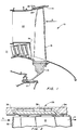
- Fig. 1 is a partial view in schematic illustrating the invention as applied to the casing of a fan of a fan jet engine of the type powering aircraft.
- Fig. 2 is an enlarged view showing the casing treatment of Fig. 1 in schematic to illustrate the flow pattern.
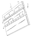
- Fig. 3 is a view in perspective showing one embodiment of a case treatment incorporating the invention.
- Fig. 4 is a perspective view showing the top surface of the structure of Fig. 3.
- this invention constitutes an improvement over the axially skewed slots disclosed in U.S. Patent No. 4,239,452, supra. It is noted that the embodiment disclosed in this patent application is directed toward the shroud that surrounds the fan of a fan jet engine, it being understood that the same principle disclosed by this concept may be equally applied to the hub supporting the fan within the scope of the invention.
- Figs. 1 and 2 the fan rotor generally illustrated by reference numeral 10 is attached to shaft 12 and is mounted on the front end of the engine and is surrounded by engine case 14.
- the fan rotor consisting of hub 16 and a plurality of axial flow fan blades 18 (one being shown) extending radially and in close proximity to the inner diameter surface of case 14.
- the case 14 may carry a shroud 20 fabricated from a suitable material to form a rub strip which serves as an outer air seal for the tips of the blades 18.
- Air flow out of the fan is split by splitter 19 where a portion flows into the engine case 21 and the remaining portion flows through the fan duct 22.
- splitter 19 Details of such engines can be had by referring to the PW4000, JT9D and F100 family of engines which are manufactured by Pratt & Whitney, a division of United Technologies Corporation, the applicant in this patent application.
- this invention is concerned with the treatment of the fan case for enhancing stall margin and is generally shown by reference numeral 26.
- a more detailed configuration is shown in Fig. 2 which shows the side profile of the tip portion of blade 18 in proximity to the case treatment 26.
- the enlarged arrow A depicts the direction of flow into the fan.
- Discrete passageways in the rub strip are designed to capture only the low rotor relative momentum flow, efficiently remove and sometimes reverse the swirl component, accelerate it, and reintroduce it into the fan flow stream in a nearly axial direction that is closely aligned with the fan rotor blade mean tip metal angle at the point of injection to result in minimal disturbance to the freestream flow inboard of the casing.
- the curvature of these passages is designed to recirculate the air as efficiently as possible and to assure the proper reintroduction of air into the fan blade stream.
- the fan air adjacent the tip is removed at some location downstream of the leading edge 32 of blade 18 through passage 34 and reintroduced at a location upstream of passageway 34 through passage 36.
- the injection position can be upstream of the rotor leading edge.
- a plurality of turning vanes 38 are circumferentially mounted intermediate passages 34 and 36.
- the forward facing wall formed in passage 34 is judiciously angled so that the weak axial flow near the casing, which can eventually stall the component, is selectively recirculated and injected back into the fan air stream at high velocity while strong axial flow tends to remain in the gas path and is not recirculated. This tends to avoid recirculating air more than once which can be detrimental to component efficiency. While the particular passage configurations and dimensions will be primarily dictated by the particular application to which this invention is utilized, it is critical that the amount of flow removed from the fan stream does not exceed 8% of the total flow into the fan.
- Figs. 3 and 4 exemplifies an integral case treatment that may be adapted as a retrofit where it is desirable to modify an existing case.
- a unit formed in accordance with this design can simply be inserted into a recess formed in the inner surface of an already existing case.
- the passageways are formed in a ring-like element 50 having a pair of banks 52 and 54 of circumferentially spaced passageways 56 and 58 respectively which are shown as rectangular in shape.
- Fig. 3 is a view of the inner surface of ring-like element 50 facing the tips of the blade.
- the first bank 52 of passageways 56 is located to be in communication with the flow downstream of the leading edge of the fan blade and the second bank 54 of passageways 58.
- the back surface or outer diameter of ring-like element 50 as shown in Fig. 4 forms annular cavities 60 and 62 adjacent the passageways 56 and 58 respectively for collecting the flow and redistributing it back into the main flow stream.
- a plurality of vanes 66 are circumferentially disposed between the banks 52 and 54 of passageways 56 and 58, respectively, and are suitably located so as to eliminate or even reverse the swirl component of the induced air.
- the passageways 56 and 58 and space 68 between vanes 66 are so dimensioned to accelerate the induced air prior to being reintroduced back into the main fan airstream.
- the distance between banks of passageways 56 and 58 and the specific location relative to the axial extent of the blades is predicated on the particular application where the invention is being employed.
- the injection ports 58 can be positioned from somewhat upstream of the rotor leading edge, to downstream of the leading edge and the intake ports 56 must be downstream of the leading edge.
- a test conducted to compare the effect of case treatment incorporating this invention with smooth wall surface and axial skewed grooves by simulating the aircraft installation of a commercial transport fan jet engine produced the following results.
- the case incorporating the invention disclosed in Figs. 3 and 4 showed a 21 percentage points improvement of stall margin over a smooth wall casing and a 10 percentage points improvement over the axial skewed grooves.
- the efficiency of the case treatment utilizing this invention exhibited one percentage point higher than the efficiency of the axial skewed grooves, and demonstrated the same efficiency as with a smooth wall.
Abstract
Description
- This invention relates to gas turbine engines and more particularly to means for enhancing stall margin of the fan without adversely impacting efficiency by incorporating a treatment to the case of the fan.
- As is well known, surge or stall is a phenomenon that is characteristic to all types of axial flow fans and compressors and occurs at a given engine operating condition and that if gone unattended could be deleterious or harmful to not only the engine's performance but to the engine itself. Hence, throughout the entire evolution from the original design through the development and the improvement stages of a gas turbine engine, those involved in this technology pay great heed to the surge characteristics of the rotating machinery to assure that the compromise between the safe operation of the engine and its performance is optimized.
- Since the point at which stall may occur limits the blades operating pressure ratio for a given corrected air weight flow and since higher pressure ratios enhance its performance, the engine's operating line is dictated by a compromise between the stall line and performance. Hence, it is always desirable to be able to raise the stall line to a higher pressure ratio for a given engine operation. For example, raising the stall line can increase the stall margin between the engine's operating line, or raising the stall line permits raising of the operating line without changing the stall margin, which obviously would result in an increase in the engine's performance. Other alternatives can use up the increased stall margin with reduced rotor speed, reduced blade count, reduced rotor chord length, or eliminated variable geometry to improve component efficiency or lower component weight and complexity.
- Experience has shown that because there are so many factors affecting stall it is not surprising that the stall line may not match its design point. In these situations the engine's hardware is typically modified to satisfy the stall margin requirement so as to meet engine specifications. It is also not surprising that this cannot always be done without degrading engine performance. This is not to say that there aren't other advantages that are attendant an increase in stall margin.
- Thus, it is ideal to be able to increase the stall margin and at the same time obtain corresponding increase in engine performance. Of course, the next best would be to be able to increase stall margin without incurring an engine performance deficit.
- As is well-known, and as to be understood for purposes of understanding the invention, rotating stall is a phenomenon that occurs whenever sufficient blades or regions of the blades stall so as to occasion a complete blockage or reversal of flow of air through the fan and/or compressor. Also flow separation on the airfoils can lead to compressor stall or rotation stall which, in turn, can lead to an overall system breakdown of the flow, i.e., surge.
- Hence, whenever stall occurs and is allowed to propagate throughout the entire or nearly entire blading, surge can ensue. It is important to understand that the surge problem can be corrected by either providing means for handling an incipient surge or designing the engine so that the engine never operates where a stall can manifest. For example, an incipient stall may be corrected simply by reducing engine power as compared to designing the engine so that its operating parameters assure that the engine always operates below a given stall line. Also, it is well-known in the art that surge may manifest in many different forms and stall may occur in one or more blades and at different regions. The most limiting stall characteristics often occur at the tip of the blade which essentially is the type of stall being addressed by this invention. More particularly, this invention is directed to enhance the stall line so as to avoid the manifestation of an incipient stall. This will serve to prevent compressor stall although it will be understood that the treatment of the casing does not affect whether or not a rotating stall could degenerate into a surge condition.
- Treatment of the casing, which sometimes is referred to as shroud or tip seal or outer air seal, to enhance the stall line is exemplified in the prior art, for example, by U.S. Patent 4,239,452. This patent discloses that axially extending skewed grooves and circumferentially extending grooves in the blade tip shroud enhance stall characteristics.
- U.S. Patent 3,580,692 teaches a honeycomb structure casing treatment for enhancing the stall characteristics.
- Other casing treatments that are known in the prior art are, for example, disclosed in the ASME paper reported in the Journal of Fluid Engineering Vol. 109 dated May 1987 entitled "Improvement of Unstable Characteristics of an Axial Flow Fan by Air-Separator Equipment" authored by Y. Mijake, T. Inola and T. Kato, and in a paper from The School of Mechanical Engineering, Cranfield Institute of Technology in Great Britain entitled "Application of Recess Vaned Casing Treatment to Axial Flow Compressor", dated February 1988 and authored by A. R. Aziman, R. L. Elder and A. B. McKenzie. The work presented in these papers is based in part on earlier work of S. K. Ivanov disclosed in his U.S. Patent 3,189,260 granted on June 15, 1965.
- The Ivanov patent and the Miyski et al paper, supra, both investigate properties of air separators for industrial fans that operate at relatively low speeds and low aerodynamic loadings while the Aziman et al paper, supra, investigates properties of air separators operating at similar low speeds but with aerodynamic loadings that are encountered in aerospace applications.
- In the main, the teachings disclosed in the two papers and the Ivanov patent, supra, relate to mechanisms that collect rotating stall cells in post-stall operation in a significantly large recess formed in the casing, turn and reorient the flow and then reintroduce the collected air back into the main compressor flow upstream of the rotor.
- Obviously, since rotating stall is a mass of cells of stalled and highly turbulent air that precesses around the rotor at a rate that is nearly half the rotating speed of the rotor and extends upstream of the rotor a significant axial distance, one skilled in the art armed with these teachings is led to believe that in order to enhance the stall line it follows that the recess should be large enough to swallow the rotating stall. Hence, knowing that rotating stall extends a significant distance upstream of the rotor and since it is a collection of a large mass of stalled air cells, a significantly large recess would be necessary in order to swallow the rotating stall. These teachings, while particularly relevant to industrial types of fans and compressors are not relevant to aircraft application inasmuch as a large recess in the casing at the inlet of the engine or in front of a compressor is intolerable. In a sense, these papers teach away from the present invention, notwithstanding the fact that both the prior art and the present invention teach means for enhancing the stall line.
- An object of this invention is to enhance stall margin of a fan of a gas turbine engine by an improved case treatment.
- According to the present invention there is provided a gas turbine engine having a fan rotor and means encasing the fan rotor for defining a main flow stream, a passageway in said encasing means having an inlet passage located downstream of the leading edge of the fan blade of said fan rotor for bleeding low momentum flow relative to the rotor from the main flow into said passageway and an outlet located at a point upstream of said inlet passage for returning said removed flow to said main flow at a velocity that is higher than the velocity of the flow in said inlet passage, anti-swirl vanes in said passageway for straightening or reversing the swirl of the low momentum flow, said passage flow being arranged to be no greater than eight percentage points of the total flow in said main flow, and said inlet passage being oriented with respect to the main flow to selectively remove from the main flow low momentum flow relative to the rotor that has low axial velocity but high absolute tangential velocity so that the strong rotor relative flow that has high axial velocity is discouraged from being recirculated in said passageway.
- Thus a feature of this invention is to provide an improved case treatment for separating low rotor relative momentum flow which has mostly a high swirl component in the absolute frame out of the main flow path and reintroducing the flow into the flow path at a higher velocity with the elimination or even reversal of the swirl component. The injected flow is preferably to be oriented at the mean rotor blade tip angle at the point of injection to result in minimal disturbance to the freestream flow inboard of the casing.
- A further feature of this invention is the removal of low rotor relative momentum flow adjacent the casing of the fan rotor and reintroducing the flow back into the mainstream upstream from the removal juncture, where the amount of removed flow is no greater than 8% of the main flow in the fan.
- A preferred embodiment of the invention will now be described by way of example only with reference to the accompanying drawings in which:
- Fig. 1 is a partial view in schematic illustrating the invention as applied to the casing of a fan of a fan jet engine of the type powering aircraft.
- Fig. 2 is an enlarged view showing the casing treatment of Fig. 1 in schematic to illustrate the flow pattern.
- Fig. 3 is a view in perspective showing one embodiment of a case treatment incorporating the invention.
- Fig. 4 is a perspective view showing the top surface of the structure of Fig. 3.
- As mentioned above, this invention constitutes an improvement over the axially skewed slots disclosed in U.S. Patent No. 4,239,452, supra. It is noted that the embodiment disclosed in this patent application is directed toward the shroud that surrounds the fan of a fan jet engine, it being understood that the same principle disclosed by this concept may be equally applied to the hub supporting the fan within the scope of the invention.
- It is also to be understood that the invention to be practical is limited to the particular envelope constraints of the engine to which this invention is applied. Thus, the passages that are adapted to effectuate the invention may typically be incorporated in the hardware already existing in or proposed for an engine.
- The concept of this invention is best understood by referring to Figs. 1 and 2. As shown in Fig. 1, the fan rotor generally illustrated by
reference numeral 10 is attached toshaft 12 and is mounted on the front end of the engine and is surrounded byengine case 14. - The fan rotor consisting of
hub 16 and a plurality of axial flow fan blades 18 (one being shown) extending radially and in close proximity to the inner diameter surface ofcase 14. Thecase 14 may carry ashroud 20 fabricated from a suitable material to form a rub strip which serves as an outer air seal for the tips of theblades 18. - Air flow out of the fan is split by
splitter 19 where a portion flows into theengine case 21 and the remaining portion flows through thefan duct 22. Details of such engines can be had by referring to the PW4000, JT9D and F100 family of engines which are manufactured by Pratt & Whitney, a division of United Technologies Corporation, the applicant in this patent application. - As mentioned earlier, this invention is concerned with the treatment of the fan case for enhancing stall margin and is generally shown by
reference numeral 26. A more detailed configuration is shown in Fig. 2 which shows the side profile of the tip portion ofblade 18 in proximity to thecase treatment 26. The enlarged arrow A depicts the direction of flow into the fan. Discrete passageways in the rub strip are designed to capture only the low rotor relative momentum flow, efficiently remove and sometimes reverse the swirl component, accelerate it, and reintroduce it into the fan flow stream in a nearly axial direction that is closely aligned with the fan rotor blade mean tip metal angle at the point of injection to result in minimal disturbance to the freestream flow inboard of the casing. It is abundantly important that the curvature of these passages is designed to recirculate the air as efficiently as possible and to assure the proper reintroduction of air into the fan blade stream. As noted, the fan air adjacent the tip is removed at some location downstream of the leadingedge 32 ofblade 18 throughpassage 34 and reintroduced at a location upstream ofpassageway 34 throughpassage 36. The injection position can be upstream of the rotor leading edge. A plurality of turning vanes 38 (one being shown) are circumferentially mountedintermediate passages passage 34 is judiciously angled so that the weak axial flow near the casing, which can eventually stall the component, is selectively recirculated and injected back into the fan air stream at high velocity while strong axial flow tends to remain in the gas path and is not recirculated. This tends to avoid recirculating air more than once which can be detrimental to component efficiency. While the particular passage configurations and dimensions will be primarily dictated by the particular application to which this invention is utilized, it is critical that the amount of flow removed from the fan stream does not exceed 8% of the total flow into the fan. - The embodiment disclosed in Figs. 3 and 4 exemplifies an integral case treatment that may be adapted as a retrofit where it is desirable to modify an existing case. A unit formed in accordance with this design can simply be inserted into a recess formed in the inner surface of an already existing case. As shown, the passageways are formed in a ring-
like element 50 having a pair ofbanks passageways like element 50 facing the tips of the blade. Thefirst bank 52 ofpassageways 56 is located to be in communication with the flow downstream of the leading edge of the fan blade and thesecond bank 54 ofpassageways 58. The back surface or outer diameter of ring-like element 50 as shown in Fig. 4 formsannular cavities passageways vanes 66 are circumferentially disposed between thebanks passageways passageways space 68 betweenvanes 66 are so dimensioned to accelerate the induced air prior to being reintroduced back into the main fan airstream. The distance between banks ofpassageways injection ports 58 can be positioned from somewhat upstream of the rotor leading edge, to downstream of the leading edge and theintake ports 56 must be downstream of the leading edge. - A test conducted to compare the effect of case treatment incorporating this invention with smooth wall surface and axial skewed grooves by simulating the aircraft installation of a commercial transport fan jet engine produced the following results. The case incorporating the invention disclosed in Figs. 3 and 4 showed a 21 percentage points improvement of stall margin over a smooth wall casing and a 10 percentage points improvement over the axial skewed grooves. Moreover, the efficiency of the case treatment utilizing this invention exhibited one percentage point higher than the efficiency of the axial skewed grooves, and demonstrated the same efficiency as with a smooth wall.
- Although this invention has been shown and described with respect to detailed embodiments thereof, it will be understood by those skilled in the art that various changes in form and detail thereof may be made without departing from the scope of the claimed invention.
Claims (7)
- A gas turbine engine having a fan rotor and means encasing the fan rotor for defining a main flow stream, a passageway in said encasing means having an inlet passage located downstream of the leading edge of the fan blade of said fan rotor for bleeding low momentum flow relative to the rotor from the main flow into said passageway and an outlet located at a point upstream of said inlet passage for returning said removed flow to said main flow at a velocity that is higher than the velocity of the flow in said inlet passage, anti-swirl vanes in said passageway for straightening or reversing the swirl of the low momentum flow, said passage flow being arranged to be no greater than eight percentage points of the total flow in said main flow, and said inlet passage being oriented with respect to the main flow to selectively remove from the main flow low momentum flow relative to the rotor that has low axial velocity but high absolute tangential velocity so that the strong rotor relative flow that has high axial velocity is discouraged from being recirculated in said passageway.
- A gas turbine engine as claimed in claim 1 wherein the encasing means includes an outer shroud surrounding the tips of the fan blades, said passageway is formed in said outer shroud, and said inlet passage and said outlet passage are disposed intermediate the trailing and leading edges of said fan blade.
- A gas turbine engine as claimed in claim 1 or 2 wherein said outlet passage faces in the direction of the flow in said main flow stream so as to inject said removed flow into the main flow.
- A gas turbine engine as claimed in any preceding claim wherein said outlet passage is arranged so as to inject said removed flow into the main flow at the mean rotor blade tip angle.
- A gas turbine engine as claimed in any preceding claim wherein said inlet passages and said outlet passages include an annular opening at the end of said passages.
- A rotor tip shroud for a gas turbine engine as claimed in any preceding claim and incorporating said passageway and said anti-swirl vanes.
- A rotor hub for a gas turbine engine as claimed in any preceding claim and incorporating said passageway and said anti-swirl vanes.
Applications Claiming Priority (2)
| Application Number | Priority Date | Filing Date | Title |
|---|---|---|---|
| US64849991A | 1991-01-30 | 1991-01-30 | |
| US648499 | 1991-01-30 |
Publications (2)
| Publication Number | Publication Date |
|---|---|
| EP0497574A1 true EP0497574A1 (en) | 1992-08-05 |
| EP0497574B1 EP0497574B1 (en) | 1995-09-20 |
Family
ID=24601038
Family Applications (1)
| Application Number | Title | Priority Date | Filing Date |
|---|---|---|---|
| EP92300748A Expired - Lifetime EP0497574B1 (en) | 1991-01-30 | 1992-01-29 | Fan case treatment |
Country Status (5)
| Country | Link |
|---|---|
| US (1) | US5308225A (en) |
| EP (1) | EP0497574B1 (en) |
| JP (1) | JP3212341B2 (en) |
| KR (1) | KR100198721B1 (en) |
| DE (1) | DE69204861T2 (en) |
Cited By (27)
| Publication number | Priority date | Publication date | Assignee | Title |
|---|---|---|---|---|
| WO1995010692A1 (en) * | 1993-10-15 | 1995-04-20 | United Technologies Corporation | Active tip flow bypass in stator vane channel |
| WO1995018922A1 (en) * | 1994-01-07 | 1995-07-13 | British Technology Group Limited | Housings for axial flow fans |
| EP0718469A1 (en) * | 1994-12-23 | 1996-06-26 | United Technologies Corporation | Compressor hub |
| EP0719908A1 (en) * | 1994-12-29 | 1996-07-03 | United Technologies Corporation | Baffled passage casing treatment for compressor blades |
| EP0719907A1 (en) * | 1994-12-29 | 1996-07-03 | United Technologies Corporation | Tip shroud assembly for gas turbine engine |
| EP0751280A1 (en) * | 1995-05-31 | 1997-01-02 | United Technologies Corporation | Flow aligned plenum endwall treatment for compressor blades |
| EP0992656A1 (en) * | 1998-10-05 | 2000-04-12 | Asea Brown Boveri AG | Turbomachine to compress or expand a compressible medium |
| EP1277967A1 (en) * | 2001-07-18 | 2003-01-22 | MTU Aero Engines GmbH | Compressor casing structure |
| EP1052376A3 (en) * | 1999-05-10 | 2003-06-04 | General Electric Company | Tip sealing method for compressors |
| EP1659293A3 (en) * | 2004-11-17 | 2006-12-20 | Rolls-Royce Deutschland Ltd & Co KG | Turbomachine |
| WO2008011864A1 (en) * | 2006-07-26 | 2008-01-31 | Mtu Aero Engines Gmbh | Gas turbine with a peripheral ring segment comprising a recirculation channel |
| EP1536146A3 (en) * | 2003-11-26 | 2008-04-02 | Rolls-Royce Deutschland Ltd & Co KG | Turbo machine and fluid extraction |
| EP2151582A2 (en) | 2008-08-08 | 2010-02-10 | Rolls-Royce Deutschland Ltd & Co KG | Flow work machine |
| CN102562666A (en) * | 2012-01-06 | 2012-07-11 | 北京航空航天大学 | Unsteady standing vortex type treatment casing |
| US8251648B2 (en) | 2008-02-28 | 2012-08-28 | Rolls-Royce Deutschland Ltd & Co Kg | Casing treatment for axial compressors in a hub area |
| US8257022B2 (en) | 2008-07-07 | 2012-09-04 | Rolls-Royce Deutschland Ltd Co KG | Fluid flow machine featuring a groove on a running gap of a blade end |
| US8419355B2 (en) | 2007-08-10 | 2013-04-16 | Rolls-Royce Deutschland Ltd & Co Kg | Fluid flow machine featuring an annulus duct wall recess |
| CN103967843A (en) * | 2013-02-04 | 2014-08-06 | 中国科学院工程热物理研究所 | Air compressor peripheral groove self-circulating and jetting combined stability extension device and method |
| US8834116B2 (en) | 2008-10-21 | 2014-09-16 | Rolls-Royce Deutschland Ltd & Co Kg | Fluid flow machine with peripheral energization near the suction side |
| EP2808556A1 (en) | 2013-05-31 | 2014-12-03 | Rolls-Royce Deutschland Ltd & Co KG | Structure assembly for a turbo machine |
| EP2808558A1 (en) | 2013-05-31 | 2014-12-03 | Rolls-Royce Deutschland Ltd & Co KG | Structure assembly for a turbomachine |
| EP2808557A1 (en) | 2013-05-31 | 2014-12-03 | Rolls-Royce Deutschland Ltd & Co KG | Structure assembly for a turbomachine |
| EP2808559A1 (en) | 2013-05-31 | 2014-12-03 | Rolls-Royce Deutschland Ltd & Co KG | Structure assembly for a turbomachine |
| EP2110559A3 (en) * | 2008-04-18 | 2015-03-25 | Rolls-Royce Deutschland Ltd & Co KG | Turbo machine with fluid re-injection to influence the boundary layer |
| US9115594B2 (en) | 2010-12-28 | 2015-08-25 | Rolls-Royce Corporation | Compressor casing treatment for gas turbine engine |
| US9885368B2 (en) | 2012-05-24 | 2018-02-06 | Carrier Corporation | Stall margin enhancement of axial fan with rotating shroud |
| WO2019102231A1 (en) * | 2017-11-27 | 2019-05-31 | University Of Leicester | A flow assembly for an axial turbomachine |
Families Citing this family (62)
| Publication number | Priority date | Publication date | Assignee | Title |
|---|---|---|---|---|
| US6244817B1 (en) * | 1996-12-05 | 2001-06-12 | Mcdonnell Douglas Corporation | Method and apparatus for a fan noise controller |
| US6164911A (en) * | 1998-11-13 | 2000-12-26 | Pratt & Whitney Canada Corp. | Low aspect ratio compressor casing treatment |
| US6231301B1 (en) | 1998-12-10 | 2001-05-15 | United Technologies Corporation | Casing treatment for a fluid compressor |
| US6379110B1 (en) * | 1999-02-25 | 2002-04-30 | United Technologies Corporation | Passively driven acoustic jet controlling boundary layers |
| US6290458B1 (en) | 1999-09-20 | 2001-09-18 | Hitachi, Ltd. | Turbo machines |
| GB2373023B (en) * | 2001-03-05 | 2004-12-22 | Rolls Royce Plc | Tip treatment bar components |
| US6585479B2 (en) * | 2001-08-14 | 2003-07-01 | United Technologies Corporation | Casing treatment for compressors |
| EP1478857B1 (en) * | 2002-02-28 | 2008-04-23 | MTU Aero Engines GmbH | Compressor with an anti-stall tip treatment |
| JP4527403B2 (en) * | 2002-02-28 | 2010-08-18 | エムテーウー・アエロ・エンジンズ・ゲーエムベーハー | Recirculation structure for turbo compressor |
| DE10218459B3 (en) * | 2002-04-25 | 2004-01-15 | Mtu Aero Engines Gmbh | Multi-stage axial compressor |
| WO2004018844A1 (en) * | 2002-08-23 | 2004-03-04 | Mtu Aero Engines Gmbh | Recirculation structure for a turbocompressor |
| US7074006B1 (en) * | 2002-10-08 | 2006-07-11 | The United States Of America As Represented By The Administrator Of National Aeronautics And Space Administration | Endwall treatment and method for gas turbine |
| DE10355241A1 (en) | 2003-11-26 | 2005-06-30 | Rolls-Royce Deutschland Ltd & Co Kg | Fluid flow machine with fluid supply |
| US7147426B2 (en) * | 2004-05-07 | 2006-12-12 | Pratt & Whitney Canada Corp. | Shockwave-induced boundary layer bleed |
| DE102004030597A1 (en) | 2004-06-24 | 2006-01-26 | Rolls-Royce Deutschland Ltd & Co Kg | Turbomachine with external wheel jet generation at the stator |
| DE102004043036A1 (en) | 2004-09-06 | 2006-03-09 | Rolls-Royce Deutschland Ltd & Co Kg | Fluid flow machine with fluid removal |
| US7553122B2 (en) * | 2005-12-22 | 2009-06-30 | General Electric Company | Self-aspirated flow control system for centrifugal compressors |
| US7475539B2 (en) * | 2006-05-24 | 2009-01-13 | Honeywell International, Inc. | Inclined rib ported shroud compressor housing |
| US20080044273A1 (en) * | 2006-08-15 | 2008-02-21 | Syed Arif Khalid | Turbomachine with reduced leakage penalties in pressure change and efficiency |
| US8038388B2 (en) * | 2007-03-05 | 2011-10-18 | United Technologies Corporation | Abradable component for a gas turbine engine |
| US8082726B2 (en) * | 2007-06-26 | 2011-12-27 | United Technologies Corporation | Tangential anti-swirl air supply |
| US8272832B2 (en) * | 2008-04-17 | 2012-09-25 | Honeywell International Inc. | Centrifugal compressor with surge control, and associated method |
| US8052375B2 (en) * | 2008-06-02 | 2011-11-08 | General Electric Company | Fluidic sealing for turbomachinery |
| US8337146B2 (en) * | 2009-06-03 | 2012-12-25 | Pratt & Whitney Canada Corp. | Rotor casing treatment with recessed baffles |
| DE102009032841A1 (en) * | 2009-07-13 | 2011-01-20 | Rolls-Royce Deutschland Ltd & Co Kg | Noise-reduced aircraft engine and method for reducing noise emissions of an aircraft engine |
| FR2949518B1 (en) * | 2009-08-31 | 2011-10-21 | Snecma | TURBOMACHINE COMPRESSOR HAVING AIR INJECTORS |
| US8540482B2 (en) | 2010-06-07 | 2013-09-24 | United Technologies Corporation | Rotor assembly for gas turbine engine |
| US8602720B2 (en) | 2010-06-22 | 2013-12-10 | Honeywell International Inc. | Compressors with casing treatments in gas turbine engines |
| EP2532898A1 (en) * | 2011-06-08 | 2012-12-12 | Siemens Aktiengesellschaft | Axial turbo compressor |
| CN102852668B (en) * | 2011-06-29 | 2015-08-12 | 中国科学院工程热物理研究所 | A kind of axial fan/gas compressor is from the jet mechanism of bleed |
| US9062558B2 (en) * | 2011-07-15 | 2015-06-23 | United Technologies Corporation | Blade outer air seal having partial coating |
| DE102011107523B4 (en) * | 2011-07-15 | 2016-08-11 | MTU Aero Engines AG | System for injecting a fluid, compressor and turbomachine |
| US9995165B2 (en) | 2011-07-15 | 2018-06-12 | United Technologies Corporation | Blade outer air seal having partial coating |
| CN103133413A (en) * | 2011-11-25 | 2013-06-05 | 中国航空工业集团公司沈阳发动机设计研究所 | Engine blower multilayer receiver structure |
| JP5567077B2 (en) * | 2012-08-23 | 2014-08-06 | 三菱重工業株式会社 | Rotating machine |
| WO2014197044A2 (en) | 2013-03-12 | 2014-12-11 | United Technologies Corporation | Vane tip machining fixture assembly |
| US9726185B2 (en) | 2013-05-14 | 2017-08-08 | Honeywell International Inc. | Centrifugal compressor with casing treatment for surge control |
| DE102013219818B3 (en) * | 2013-09-30 | 2015-02-05 | Deutsches Zentrum für Luft- und Raumfahrt e.V. | axial compressor |
| JP6131177B2 (en) * | 2013-12-03 | 2017-05-17 | 三菱重工業株式会社 | Seal structure and rotating machine |
| FR3015593B1 (en) * | 2013-12-20 | 2018-09-07 | Safran Aircraft Engines | CARRIER IN COMPOSITE MATRIX WITH ORGANIC MATRIX FOR THE EVACUATION OF SMOKE |
| US10036263B2 (en) | 2014-10-22 | 2018-07-31 | United Technologies Corporation | Stator assembly with pad interface for a gas turbine engine |
| CN104405685A (en) * | 2014-11-20 | 2015-03-11 | 哈尔滨广瀚燃气轮机有限公司 | Self-circulation and circumferential groove hybrid treater box for improving performance of air compressor |
| CN104675755B (en) * | 2015-01-14 | 2017-03-29 | 西北工业大学 | Axial flow compressor circumferential misalignment type is from the treated casing method that circulates |
| US9932985B2 (en) * | 2015-02-03 | 2018-04-03 | Honeywell International Inc. | Gas turbine engine compressors having optimized stall enhancement feature configurations and methods for the production thereof |
| US10107307B2 (en) * | 2015-04-14 | 2018-10-23 | Pratt & Whitney Canada Corp. | Gas turbine engine rotor casing treatment |
| DE102016118369A1 (en) | 2016-09-28 | 2018-03-29 | Ebm-Papst Mulfingen Gmbh & Co. Kg | Suction nozzle and blow-out unit of a fan |
| US10683076B2 (en) | 2017-10-31 | 2020-06-16 | Coflow Jet, LLC | Fluid systems that include a co-flow jet |
| US11293293B2 (en) * | 2018-01-22 | 2022-04-05 | Coflow Jet, LLC | Turbomachines that include a casing treatment |
| US10830102B2 (en) | 2018-03-01 | 2020-11-10 | General Electric Company | Casing with tunable lattice structure |
| TWI671470B (en) * | 2018-05-04 | 2019-09-11 | 奇鋐科技股份有限公司 | Fan noise reduction structure |
| CN108412816B (en) * | 2018-05-10 | 2021-06-18 | 奇鋐科技股份有限公司 | Noise reduction structure of fan |
| US11326623B2 (en) | 2018-05-15 | 2022-05-10 | Asia Vital Components Co., Ltd. | Fan noise-lowering structure |
| US11326624B2 (en) | 2018-05-15 | 2022-05-10 | Asia Vital Components Co., Ltd. | Fan noise-lowering structure |
| US10914318B2 (en) | 2019-01-10 | 2021-02-09 | General Electric Company | Engine casing treatment for reducing circumferentially variable distortion |
| US11047249B2 (en) * | 2019-05-01 | 2021-06-29 | Raytheon Technologies Corporation | Labyrinth seal with passive check valve |
| WO2021016321A1 (en) | 2019-07-23 | 2021-01-28 | Gecheng Zha | Fluid systems and methods that address flow separation |
| CN111734685B (en) * | 2020-07-07 | 2021-11-02 | 江西乐富军工装备有限公司 | Ventilation device |
| US20230184125A1 (en) * | 2021-12-15 | 2023-06-15 | General Electric Company | Engine component with abradable material and treatment |
| US11732612B2 (en) | 2021-12-22 | 2023-08-22 | Rolls-Royce North American Technologies Inc. | Turbine engine fan track liner with tip injection air recirculation passage |
| US11702945B2 (en) | 2021-12-22 | 2023-07-18 | Rolls-Royce North American Technologies Inc. | Turbine engine fan case with tip injection air recirculation passage |
| US11946379B2 (en) * | 2021-12-22 | 2024-04-02 | Rolls-Royce North American Technologies Inc. | Turbine engine fan case with manifolded tip injection air recirculation passages |
| CN114838002B (en) * | 2022-04-23 | 2024-01-30 | 西北工业大学 | Stability expanding processing device of self-circulation casing |
Citations (5)
| Publication number | Priority date | Publication date | Assignee | Title |
|---|---|---|---|---|
| GB504214A (en) * | 1937-02-24 | 1939-04-21 | Rheinmetall Borsig Ag Werk Bor | Improvements in and relating to turbo compressors |
| GB825967A (en) * | 1956-03-28 | 1959-12-23 | Robert Jean Pouit | Improvements in turbines and in particular gas turbines |
| FR2325830A1 (en) * | 1975-09-25 | 1977-04-22 | Rolls Royce | COMPRESSOR HOUSINGS FOR GAS TURBINE ENGINES |
| GB2017228A (en) * | 1977-07-14 | 1979-10-03 | Pratt & Witney Aircraft Of Can | Shroud for a turbine rotor |
| WO1985000640A1 (en) * | 1983-07-28 | 1985-02-14 | Nordisk Ventilator Co. A/S | Axial-flow fan |
Family Cites Families (9)
| Publication number | Priority date | Publication date | Assignee | Title |
|---|---|---|---|---|
| US948692A (en) * | 1910-02-08 | Willis G Dodd | Rotary engine. | |
| US743883A (en) * | 1903-07-30 | 1903-11-10 | Morgan D Kalbach | Rotary engine. |
| US1349487A (en) * | 1917-05-31 | 1920-08-10 | Erastus S Bennett | Turbine-engine |
| US2709917A (en) * | 1952-02-15 | 1955-06-07 | United Aircraft Corp | Transonic flow control |
| JPS5211405A (en) * | 1975-07-17 | 1977-01-28 | Mitsubishi Heavy Ind Ltd | Pump with inducer |
| US4212585A (en) * | 1978-01-20 | 1980-07-15 | Northern Research And Engineering Corporation | Centrifugal compressor |
| US4375937A (en) * | 1981-01-28 | 1983-03-08 | Ingersoll-Rand Company | Roto-dynamic pump with a backflow recirculator |
| DE3539604C1 (en) * | 1985-11-08 | 1987-02-19 | Turbo Lufttechnik Gmbh | Axial fan |
| CH675279A5 (en) * | 1988-06-29 | 1990-09-14 | Asea Brown Boveri |
-
1992
- 1992-01-29 DE DE69204861T patent/DE69204861T2/en not_active Expired - Lifetime
- 1992-01-29 KR KR1019920001306A patent/KR100198721B1/en not_active IP Right Cessation
- 1992-01-29 EP EP92300748A patent/EP0497574B1/en not_active Expired - Lifetime
- 1992-01-30 JP JP04015892A patent/JP3212341B2/en not_active Expired - Fee Related
- 1992-07-28 US US07/925,312 patent/US5308225A/en not_active Expired - Lifetime
Patent Citations (5)
| Publication number | Priority date | Publication date | Assignee | Title |
|---|---|---|---|---|
| GB504214A (en) * | 1937-02-24 | 1939-04-21 | Rheinmetall Borsig Ag Werk Bor | Improvements in and relating to turbo compressors |
| GB825967A (en) * | 1956-03-28 | 1959-12-23 | Robert Jean Pouit | Improvements in turbines and in particular gas turbines |
| FR2325830A1 (en) * | 1975-09-25 | 1977-04-22 | Rolls Royce | COMPRESSOR HOUSINGS FOR GAS TURBINE ENGINES |
| GB2017228A (en) * | 1977-07-14 | 1979-10-03 | Pratt & Witney Aircraft Of Can | Shroud for a turbine rotor |
| WO1985000640A1 (en) * | 1983-07-28 | 1985-02-14 | Nordisk Ventilator Co. A/S | Axial-flow fan |
Cited By (41)
| Publication number | Priority date | Publication date | Assignee | Title |
|---|---|---|---|---|
| WO1995010692A1 (en) * | 1993-10-15 | 1995-04-20 | United Technologies Corporation | Active tip flow bypass in stator vane channel |
| US5431533A (en) * | 1993-10-15 | 1995-07-11 | United Technologies Corporation | Active vaned passage casing treatment |
| WO1995018922A1 (en) * | 1994-01-07 | 1995-07-13 | British Technology Group Limited | Housings for axial flow fans |
| EP0718469A1 (en) * | 1994-12-23 | 1996-06-26 | United Technologies Corporation | Compressor hub |
| EP0719908A1 (en) * | 1994-12-29 | 1996-07-03 | United Technologies Corporation | Baffled passage casing treatment for compressor blades |
| EP0719907A1 (en) * | 1994-12-29 | 1996-07-03 | United Technologies Corporation | Tip shroud assembly for gas turbine engine |
| EP0751280A1 (en) * | 1995-05-31 | 1997-01-02 | United Technologies Corporation | Flow aligned plenum endwall treatment for compressor blades |
| US6264425B1 (en) | 1998-10-05 | 2001-07-24 | Asea Brown Boveri Ag | Fluid-flow machine for compressing or expanding a compressible medium |
| EP0992656A1 (en) * | 1998-10-05 | 2000-04-12 | Asea Brown Boveri AG | Turbomachine to compress or expand a compressible medium |
| EP1052376A3 (en) * | 1999-05-10 | 2003-06-04 | General Electric Company | Tip sealing method for compressors |
| EP1277967A1 (en) * | 2001-07-18 | 2003-01-22 | MTU Aero Engines GmbH | Compressor casing structure |
| US6742983B2 (en) | 2001-07-18 | 2004-06-01 | Mtu Aero Engines Gmbh | Compressor casing structure |
| EP1536146A3 (en) * | 2003-11-26 | 2008-04-02 | Rolls-Royce Deutschland Ltd & Co KG | Turbo machine and fluid extraction |
| EP1659293A3 (en) * | 2004-11-17 | 2006-12-20 | Rolls-Royce Deutschland Ltd & Co KG | Turbomachine |
| WO2008011864A1 (en) * | 2006-07-26 | 2008-01-31 | Mtu Aero Engines Gmbh | Gas turbine with a peripheral ring segment comprising a recirculation channel |
| US8092148B2 (en) | 2006-07-26 | 2012-01-10 | Mtu Aero Engines Gmbh | Gas turbine having a peripheral ring segment including a recirculation channel |
| US8419355B2 (en) | 2007-08-10 | 2013-04-16 | Rolls-Royce Deutschland Ltd & Co Kg | Fluid flow machine featuring an annulus duct wall recess |
| US8251648B2 (en) | 2008-02-28 | 2012-08-28 | Rolls-Royce Deutschland Ltd & Co Kg | Casing treatment for axial compressors in a hub area |
| EP2110559A3 (en) * | 2008-04-18 | 2015-03-25 | Rolls-Royce Deutschland Ltd & Co KG | Turbo machine with fluid re-injection to influence the boundary layer |
| US8257022B2 (en) | 2008-07-07 | 2012-09-04 | Rolls-Royce Deutschland Ltd Co KG | Fluid flow machine featuring a groove on a running gap of a blade end |
| US8382422B2 (en) | 2008-08-08 | 2013-02-26 | Rolls-Royce Deutschland Ltd & Co Kg | Fluid flow machine |
| DE102008037154A1 (en) | 2008-08-08 | 2010-02-11 | Rolls-Royce Deutschland Ltd & Co Kg | Turbomachine |
| EP2151582A2 (en) | 2008-08-08 | 2010-02-10 | Rolls-Royce Deutschland Ltd & Co KG | Flow work machine |
| US8834116B2 (en) | 2008-10-21 | 2014-09-16 | Rolls-Royce Deutschland Ltd & Co Kg | Fluid flow machine with peripheral energization near the suction side |
| US9115594B2 (en) | 2010-12-28 | 2015-08-25 | Rolls-Royce Corporation | Compressor casing treatment for gas turbine engine |
| CN102562666A (en) * | 2012-01-06 | 2012-07-11 | 北京航空航天大学 | Unsteady standing vortex type treatment casing |
| US9885368B2 (en) | 2012-05-24 | 2018-02-06 | Carrier Corporation | Stall margin enhancement of axial fan with rotating shroud |
| CN103967843A (en) * | 2013-02-04 | 2014-08-06 | 中国科学院工程热物理研究所 | Air compressor peripheral groove self-circulating and jetting combined stability extension device and method |
| DE102013210169A1 (en) | 2013-05-31 | 2014-12-04 | Rolls-Royce Deutschland Ltd & Co Kg | Structural assembly for a turbomachine |
| DE102013210171A1 (en) | 2013-05-31 | 2014-12-04 | Rolls-Royce Deutschland Ltd & Co Kg | Structural assembly for a turbomachine |
| EP2808559A1 (en) | 2013-05-31 | 2014-12-03 | Rolls-Royce Deutschland Ltd & Co KG | Structure assembly for a turbomachine |
| DE102013210167A1 (en) | 2013-05-31 | 2014-12-04 | Rolls-Royce Deutschland Ltd & Co Kg | Structural assembly for a turbomachine |
| DE102013210168A1 (en) | 2013-05-31 | 2014-12-04 | Rolls-Royce Deutschland Ltd & Co Kg | Structural assembly for a turbomachine |
| EP2808557A1 (en) | 2013-05-31 | 2014-12-03 | Rolls-Royce Deutschland Ltd & Co KG | Structure assembly for a turbomachine |
| EP2808558A1 (en) | 2013-05-31 | 2014-12-03 | Rolls-Royce Deutschland Ltd & Co KG | Structure assembly for a turbomachine |
| US9587509B2 (en) | 2013-05-31 | 2017-03-07 | Rolls-Royce Deutschland Ltd & Co Kg | Assembly for a fluid flow machine |
| US9664204B2 (en) | 2013-05-31 | 2017-05-30 | Rolls-Royce Deutschland Ltd & Co Kg | Assembly for a fluid flow machine |
| US9822792B2 (en) | 2013-05-31 | 2017-11-21 | Rolls-Royce Deutschland Ltd & Co Kg | Assembly for a fluid flow machine |
| EP2808556A1 (en) | 2013-05-31 | 2014-12-03 | Rolls-Royce Deutschland Ltd & Co KG | Structure assembly for a turbo machine |
| US10006467B2 (en) | 2013-05-31 | 2018-06-26 | Rolls-Royce Deutschland Ltd & Co Kg | Assembly for a fluid flow machine |
| WO2019102231A1 (en) * | 2017-11-27 | 2019-05-31 | University Of Leicester | A flow assembly for an axial turbomachine |
Also Published As
| Publication number | Publication date |
|---|---|
| JP3212341B2 (en) | 2001-09-25 |
| KR920015020A (en) | 1992-08-26 |
| JPH04314931A (en) | 1992-11-06 |
| EP0497574B1 (en) | 1995-09-20 |
| US5308225A (en) | 1994-05-03 |
| DE69204861T2 (en) | 1996-05-23 |
| KR100198721B1 (en) | 1999-06-15 |
| DE69204861D1 (en) | 1995-10-26 |
Similar Documents
| Publication | Publication Date | Title |
|---|---|---|
| EP0497574B1 (en) | Fan case treatment | |
| US5282718A (en) | Case treatment for compressor blades | |
| US7575412B2 (en) | Anti-stall casing treatment for turbo compressors | |
| US8235658B2 (en) | Fluid flow machine including rotors with small rotor exit angles | |
| EP2803866B1 (en) | Centrifugal compressor with casing treatment for surge control | |
| US4318669A (en) | Vane configuration for fluid wake re-energization | |
| KR910002410B1 (en) | Centrifugal compressor | |
| EP3483395B1 (en) | Inter-turbine ducts with flow control mechanisms | |
| CN109139255B (en) | Exhaust assembly with vortex generator and exhaust method thereof | |
| WO2015072256A1 (en) | Vane structure for axial flow turbomachine and gas turbine engine | |
| US6312221B1 (en) | End wall flow path of a compressor | |
| EP3098383B1 (en) | Compressor airfoil with compound leading edge profile | |
| US8038409B2 (en) | Turbomachine with rotors of high specific energy transfer | |
| JP6352284B2 (en) | Turbine engine compression assembly | |
| WO2016047256A1 (en) | Turbo machine | |
| US4934139A (en) | Turbofan gas turbine engine | |
| WO2019102231A1 (en) | A flow assembly for an axial turbomachine | |
| EP3354848A1 (en) | Inter-turbine ducts with multiple splitter blades | |
| JP3432674B2 (en) | Multistage centrifugal compressor | |
| JPH08159097A (en) | Fan and casing of compressor | |
| US11434765B2 (en) | Turbine engine with airfoil having high acceleration and low blade turning | |
| EP3770379B1 (en) | Compressor stator | |
| EP0533319A1 (en) | Aerofoil members for gas turbine engines | |
| JP2007138816A (en) | Method and device for bleeding multiple stage centrifugal compressor | |
| JPH05312192A (en) | Axial flow fan |
Legal Events
| Date | Code | Title | Description |
|---|---|---|---|
| PUAI | Public reference made under article 153(3) epc to a published international application that has entered the european phase |
Free format text: ORIGINAL CODE: 0009012 |
|
| AK | Designated contracting states |
Kind code of ref document: A1 Designated state(s): DE FR GB IT |
|
| 17P | Request for examination filed |
Effective date: 19921102 |
|
| 17Q | First examination report despatched |
Effective date: 19931112 |
|
| GRAA | (expected) grant |
Free format text: ORIGINAL CODE: 0009210 |
|
| AK | Designated contracting states |
Kind code of ref document: B1 Designated state(s): DE FR GB IT |
|
| REF | Corresponds to: |
Ref document number: 69204861 Country of ref document: DE Date of ref document: 19951026 |
|
| ET | Fr: translation filed | ||
| ITF | It: translation for a ep patent filed |
Owner name: BARZANO' E ZANARDO ROMA S.P.A. |
|
| PLBE | No opposition filed within time limit |
Free format text: ORIGINAL CODE: 0009261 |
|
| STAA | Information on the status of an ep patent application or granted ep patent |
Free format text: STATUS: NO OPPOSITION FILED WITHIN TIME LIMIT |
|
| 26N | No opposition filed | ||
| REG | Reference to a national code |
Ref country code: GB Ref legal event code: IF02 |
|
| PGFP | Annual fee paid to national office [announced via postgrant information from national office to epo] |
Ref country code: IT Payment date: 20060131 Year of fee payment: 15 |
|
| PG25 | Lapsed in a contracting state [announced via postgrant information from national office to epo] |
Ref country code: IT Free format text: LAPSE BECAUSE OF NON-PAYMENT OF DUE FEES Effective date: 20070129 |
|
| PGFP | Annual fee paid to national office [announced via postgrant information from national office to epo] |
Ref country code: FR Payment date: 20100208 Year of fee payment: 19 |
|
| PGFP | Annual fee paid to national office [announced via postgrant information from national office to epo] |
Ref country code: DE Payment date: 20110126 Year of fee payment: 20 |
|
| PGFP | Annual fee paid to national office [announced via postgrant information from national office to epo] |
Ref country code: GB Payment date: 20110126 Year of fee payment: 20 |
|
| REG | Reference to a national code |
Ref country code: FR Ref legal event code: ST Effective date: 20110930 |
|
| PG25 | Lapsed in a contracting state [announced via postgrant information from national office to epo] |
Ref country code: FR Free format text: LAPSE BECAUSE OF NON-PAYMENT OF DUE FEES Effective date: 20110131 |
|
| REG | Reference to a national code |
Ref country code: DE Ref legal event code: R071 Ref document number: 69204861 Country of ref document: DE |
|
| REG | Reference to a national code |
Ref country code: DE Ref legal event code: R071 Ref document number: 69204861 Country of ref document: DE |
|
| REG | Reference to a national code |
Ref country code: GB Ref legal event code: PE20 Expiry date: 20120128 |
|
| PG25 | Lapsed in a contracting state [announced via postgrant information from national office to epo] |
Ref country code: DE Free format text: LAPSE BECAUSE OF EXPIRATION OF PROTECTION Effective date: 20120130 |
|
| PG25 | Lapsed in a contracting state [announced via postgrant information from national office to epo] |
Ref country code: GB Free format text: LAPSE BECAUSE OF EXPIRATION OF PROTECTION Effective date: 20120128 |