WO2015072256A1 - Vane structure for axial flow turbomachine and gas turbine engine - Google Patents
Vane structure for axial flow turbomachine and gas turbine engine Download PDFInfo
- Publication number
- WO2015072256A1 WO2015072256A1 PCT/JP2014/077151 JP2014077151W WO2015072256A1 WO 2015072256 A1 WO2015072256 A1 WO 2015072256A1 JP 2014077151 W JP2014077151 W JP 2014077151W WO 2015072256 A1 WO2015072256 A1 WO 2015072256A1
- Authority
- WO
- WIPO (PCT)
- Prior art keywords
- blade
- wing
- tandem
- peripheral surface
- axial
- Prior art date
Links
Images


Classifications
-
- F—MECHANICAL ENGINEERING; LIGHTING; HEATING; WEAPONS; BLASTING
- F01—MACHINES OR ENGINES IN GENERAL; ENGINE PLANTS IN GENERAL; STEAM ENGINES
- F01D—NON-POSITIVE DISPLACEMENT MACHINES OR ENGINES, e.g. STEAM TURBINES
- F01D5/00—Blades; Blade-carrying members; Heating, heat-insulating, cooling or antivibration means on the blades or the members
- F01D5/12—Blades
- F01D5/14—Form or construction
- F01D5/141—Shape, i.e. outer, aerodynamic form
- F01D5/146—Shape, i.e. outer, aerodynamic form of blades with tandem configuration, split blades or slotted blades
-
- F—MECHANICAL ENGINEERING; LIGHTING; HEATING; WEAPONS; BLASTING
- F01—MACHINES OR ENGINES IN GENERAL; ENGINE PLANTS IN GENERAL; STEAM ENGINES
- F01D—NON-POSITIVE DISPLACEMENT MACHINES OR ENGINES, e.g. STEAM TURBINES
- F01D9/00—Stators
- F01D9/02—Nozzles; Nozzle boxes; Stator blades; Guide conduits, e.g. individual nozzles
- F01D9/04—Nozzles; Nozzle boxes; Stator blades; Guide conduits, e.g. individual nozzles forming ring or sector
- F01D9/041—Nozzles; Nozzle boxes; Stator blades; Guide conduits, e.g. individual nozzles forming ring or sector using blades
-
- F—MECHANICAL ENGINEERING; LIGHTING; HEATING; WEAPONS; BLASTING
- F05—INDEXING SCHEMES RELATING TO ENGINES OR PUMPS IN VARIOUS SUBCLASSES OF CLASSES F01-F04
- F05D—INDEXING SCHEME FOR ASPECTS RELATING TO NON-POSITIVE-DISPLACEMENT MACHINES OR ENGINES, GAS-TURBINES OR JET-PROPULSION PLANTS
- F05D2220/00—Application
- F05D2220/30—Application in turbines
- F05D2220/32—Application in turbines in gas turbines
-
- F—MECHANICAL ENGINEERING; LIGHTING; HEATING; WEAPONS; BLASTING
- F05—INDEXING SCHEMES RELATING TO ENGINES OR PUMPS IN VARIOUS SUBCLASSES OF CLASSES F01-F04
- F05D—INDEXING SCHEME FOR ASPECTS RELATING TO NON-POSITIVE-DISPLACEMENT MACHINES OR ENGINES, GAS-TURBINES OR JET-PROPULSION PLANTS
- F05D2250/00—Geometry
- F05D2250/70—Shape
- F05D2250/71—Shape curved
- F05D2250/711—Shape curved convex
-
- Y—GENERAL TAGGING OF NEW TECHNOLOGICAL DEVELOPMENTS; GENERAL TAGGING OF CROSS-SECTIONAL TECHNOLOGIES SPANNING OVER SEVERAL SECTIONS OF THE IPC; TECHNICAL SUBJECTS COVERED BY FORMER USPC CROSS-REFERENCE ART COLLECTIONS [XRACs] AND DIGESTS
- Y02—TECHNOLOGIES OR APPLICATIONS FOR MITIGATION OR ADAPTATION AGAINST CLIMATE CHANGE
- Y02T—CLIMATE CHANGE MITIGATION TECHNOLOGIES RELATED TO TRANSPORTATION
- Y02T50/00—Aeronautics or air transport
- Y02T50/60—Efficient propulsion technologies, e.g. for aircraft
Definitions
- the present invention relates to a blade structure of an axial-flow turbomachine and a gas turbine engine that are improved in efficiency.
- An axial flow turbomachine such as an axial flow compressor or an axial flow turbine includes a rotor including a plurality of moving blades and a stator including a plurality of stationary blades arranged in a plurality of stages in the axial direction.
- Axial turbomachines are often used, for example, in aircraft gas turbine engines.
- a moving blade or stationary blade of an axial flow turbomachine the flow is accelerated on the back side of the blade.
- a blade is designed so that the position where the flow velocity reaches the maximum (that is, the position where the peak Mach number is reached) is as close as possible to the trailing edge side of the blade.
- the position at which the maximum speed is reached is the trailing edge of the blade, there is no region where the flow slows down in the blade.
- the position where the maximum speed is reached is located ahead of the trailing edge of the blade, the airflow is decelerated between that position and the trailing edge of the blade. In this case, separation may occur due to the deceleration region and efficiency may be reduced, or a secondary flow (a flow having a swirling component whose direction is different from that of the main gas flow) may occur.
- Patent Document 1 discloses a tandem cascade composed of tandem wings formed by combining a front wing and a rear wing. Such a tandem cascade adjusts the speed and momentum of the jet so that the jet that blows from the rear edge of the lower surface of the front wing to the upper surface of the rear wing flows along the upper surface of the rear wing. Boundary layer peeling is suppressed.
- Patent Document 2 discloses a structure of a compressor including a tandem moving blade and a tandem stationary blade that is downstream of the tandem moving blade and turns the flow from the tandem moving blade to a predetermined angle. Similar to Patent Document 1, the tandem moving blade and the tandem stationary blade are configured to suppress separation of the boundary layer on the upper surface of the rear wing. Patent Document 2 aims to obtain a higher pressure ratio with a smaller number of stages by arranging such tandem moving blades and tandem stationary blades alternately in multiple stages.
- the moving blades and stationary blades are arranged radially in the radial direction of the axial flow turbomachine.
- the speed ratio on one end side in the blade longitudinal direction and the speed ratio on the other end side of each blade are different.
- the speed ratio is the ratio of the speed (outlet speed) at the outlet of the blade to the flow speed (inlet speed) at the inlet of the blade. That is, the speed ratio is a value obtained by dividing the outlet speed by the inlet speed.
- the speed ratio is large at one end side in the blade longitudinal direction. Therefore, it is relatively easy to set the position of the maximum speed near the trailing edge.
- the speed ratio is relatively smaller on the other end side in the blade longitudinal direction than on the one end side. Therefore, there is a problem that the position of the maximum speed tends to be a position ahead of the rear edge, and a deceleration region is generated.
- the tandem wing described in Patent Document 1 and Patent Document 2 attempts to suppress separation of the boundary layer on the upper surface of the rear wing by separating the entire wing into a front wing and a rear wing.
- a uniform effect is not obtained in the entire region in the blade longitudinal direction. That is, if one end side in the blade longitudinal direction with a large speed ratio is used as a reference, it is difficult to suppress separation on the other end side in the blade longitudinal direction with a small speed ratio.
- the other end side in the blade longitudinal direction with a small speed ratio is used as a reference, the blowing force at one end side in the blade longitudinal direction with a large speed ratio becomes too strong, causing secondary flow. .
- An object of the present invention is to provide an axial-flow turbomachine blade structure and a gas turbine engine that can perform the above-described operation.
- 1st aspect of this invention is the structure of the blade
- the gist of a second aspect of the present invention is a gas turbine engine, which includes an axial flow turbomachine including blades having the structure according to the first aspect as moving blades or stationary blades.
- the tandem wing portion may be formed on the side having the smaller speed ratio among the one end side and the other end side in the blade longitudinal direction.
- the single wing portion may be formed on a side having a larger speed ratio among one end side and the other end side in the blade longitudinal direction.
- the tandem wing portion may be formed on a surface having a large inclination angle among an inner peripheral surface and an outer peripheral surface in the radial direction of the flow path.
- the single wing portion may be formed on a surface having a small inclination angle among an inner peripheral surface and an outer peripheral surface in the radial direction of the flow path.
- the single wing portion and the tandem wing portion may constitute the moving blade.
- the tandem wing portion may be located on the inner peripheral surface side of the flow path in the radial direction.
- the single wing portion and the tandem wing portion may constitute the stationary blade.
- the tandem wing portion may be located on the inner peripheral surface side or the outer peripheral surface side of the flow path in the radial direction.
- the back side of the rear wing may be continuous with the back side of the single wing part.
- the front wing may be inclined with respect to the single wing portion.
- the load in the deceleration region at the blade trailing edge that causes a reduction in efficiency is distributed to the front blade and the rear blade of the tandem blade.
- the deceleration area of the entire blade can be reduced, and the efficiency can be improved.
- tandem wing part consisting of a front wing and a rear wing on a part of a moving blade or stationary blade
- the secondary flow tends to grow toward the rear edge.
- the static pressure difference between the side and the ventral side can be eliminated, the secondary flow can be reduced, and the efficiency can be improved.
- FIG. 1 is a side sectional view of a turbine portion of a gas turbine engine according to an embodiment of the present invention.
- 2 (a) to 2 (c) are explanatory views showing the structure of the moving blade and stationary blade shown in FIG. 1
- FIG. 2 (a) is a perspective view of the stationary blade
- FIG. FIG. 2C is a sectional view of a region X in FIG. 2B.
- FIG. 3 is an explanatory diagram showing a change in speed ratio according to the radial position (blade longitudinal direction position) of the moving blade and the stationary blade.
- FIG. 4 is an explanatory diagram showing changes in the airflow velocity from the leading edge to the trailing edge of the wing structure in the prior art.
- FIG. 5 is an explanatory diagram showing changes in the airflow velocity of the wing structure according to the present embodiment.
- 6 (a) and 6 (b) are explanatory diagrams for illustrating one of the effects of the structure of the wing according to the present embodiment
- FIG. 6 (a) is a cross-sectional view of the structure of the conventional wing.
- FIG. 6B shows a sectional view of the structure of the wing according to the present embodiment.
- the gas turbine engine according to the present embodiment includes a rotor 11 having a plurality of moving blades 1 and a stator 21 having a plurality of stationary blades 2.
- a blade structure of an axial flow turbomachine which will be described later, is applied to the moving blade 1 and the stationary blade 2.
- the gas turbine engine is, for example, a jet engine, and has an intake port, a compressor, a combustion chamber, a turbine, and an exhaust port from the upstream side (not shown).
- the rotor 11 and stator 21 of FIG. 1 are illustrated as part of the turbine. Note that the blade structure according to the present embodiment can also be applied to a moving blade and a stationary blade of a compressor.
- the turbine flow path 3 has an annular cross section disposed around the rotation axis L and extends substantially along the rotation axis L.
- the flow path 3 has an inner peripheral surface 31 on the radially inner side and an outer peripheral surface 32 on the radially outer side.
- the radial direction coincides with the blade longitudinal direction.
- the rotor 11 includes a moving blade 1 and a platform that supports a root portion of the moving blade 1 and forms an inner peripheral surface 31.
- the stator 21 includes an outer circumferential surface 32, a stationary blade 2 fixed (supported) to the outer circumferential surface 32, and a platform that is provided on the radially inner side of the stationary blade 2 and constitutes the inner circumferential surface 31. As shown in FIG.
- the platforms of the moving blade 1 and the stationary blade 2 are continuously formed so as to form a flow path surface (inner peripheral surface 31) having a predetermined shape as a whole.
- the outer peripheral surface 32 comprises a part of casing which covers the outer periphery of a turbine.
- the moving blade 1 includes a single blade portion 1s formed in a part of the blade longitudinal direction, and a tandem blade formed in the remaining portion in the blade longitudinal direction connected to the single blade portion 1s. Part 1t.
- the single wing portion 1s and the tandem wing portion 1t form one wing body extending in the wing longitudinal direction, and the single wing portion 1s is provided in a part of the wing body in the wing longitudinal direction. It is provided in the remaining part of the blade body in the blade longitudinal direction.
- the moving blade 1 has a single blade portion 1s extending in the blade longitudinal direction and a tandem blade portion 1t connected to the single blade portion 1s in the blade longitudinal direction. As shown in FIGS.
- the single wing portion 1s has a structure constituted by a single blade.
- the tandem blade portion 1t includes a front blade 12 disposed in front of an airflow flowing through a turbine (that is, an axial turbomachine) and a rear blade 13 disposed behind the airflow.
- the tandem wing portion 1t is composed of the front wing 12 disposed in the front and the rear wing 13 disposed in the rear in the airflow flowing through the turbine.
- the stationary blade 2 also includes a single blade portion 2s formed in a part of the blade longitudinal direction, and a tandem blade formed in the remaining portion in the blade longitudinal direction connected to the single blade portion 2s.
- Part 2t the single wing portion 2s and the tandem wing portion 2t form one wing body extending in the wing longitudinal direction
- the single wing portion 2s is provided in a part of the wing body in the wing longitudinal direction
- the tandem wing portion 2t is It is provided in the remaining part of the blade body in the blade longitudinal direction.
- the stationary blade 2 has a single blade portion 2s extending in the blade longitudinal direction, and a tandem blade portion 2t connected to the single blade portion 2s in the blade longitudinal direction.
- the single wing portion 2s has a structure constituted by a single blade.
- the tandem wing part 2t like the tandem wing part 1t of the moving blade 1, has a front wing 22 disposed in front of the airflow flowing through the turbine (that is, the axial flow turbomachine) and a rearward of the airflow.
- the rear wing 23 is arranged.
- the tandem blade portion 2t includes the front blade 22 disposed in the front and the rear blade 23 disposed rearward in the airflow flowing through the turbine.
- FIG. 1 The broken lines in FIG. 1 indicate the portions where the tandem wing portions 1t and 2t are formed.
- a tandem blade portion 1t is formed on the inner peripheral surface 31 side of the flow path 3, and a single blade portion 1s is formed on the outer peripheral surface 32 side of the flow path 3.
- the tandem blade portion 2 t is formed on the outer peripheral surface 32 side of the flow channel 3
- the single blade portion 2 s is formed on the inner peripheral surface 31 side of the flow channel 3. That is, the arrangement (arrangement) of the single blade portions 1s, 2s and the tandem blade portions 1t, 2t in the radial direction (blade longitudinal direction) is reversed between the moving blade 1 and the stationary blade 2.
- FIG. 3 is an explanatory view showing a change in speed ratio according to the radial position (blade longitudinal direction) of the moving blade and the stationary blade.
- the horizontal axis indicates the speed ratio (exit speed / inlet speed), and the vertical axis indicates the radial position.
- the solid line in the figure indicates the speed ratio of the moving blade 1, and the alternate long and short dash line indicates the speed ratio of the stationary blade 2.
- the speed ratio of the moving blade 1 is such that the inner side (inner peripheral surface 31 side) in the blade longitudinal direction (turbine radial direction) is more outer than the outer side (outer peripheral surface 32 side). Is also small.
- the speed ratio in the stationary blade 2 is smaller on the outer side (outer peripheral surface 32 side) in the blade longitudinal direction (turbine radial direction) than on the inner side (inner peripheral surface 31 side).
- the tandem blade portion 1t of the moving blade 1 and the tandem blade portion 2t of the stationary blade 2 are formed in a range surrounded by a broken line in the figure.
- tandem wing part 1t of the moving blade 1 and the tandem wing part 2t of the stationary blade 2 are formed on the side having the smaller speed ratio among the one end side and the other end side in the blade longitudinal direction.
- the single blade part 1s of the moving blade 1 and the single blade part 2s of the stationary blade 2 are formed on the side having the larger speed ratio among the one end side and the other end side in the blade longitudinal direction.
- the speed ratio on the outer peripheral surface 32 side of the rotor blade 1 is larger than the speed ratio on the inner peripheral surface 31 side.
- the peripheral speed (circumferential speed) on the outer peripheral surface 32 side of the rotor blade 1 is larger than the peripheral speed (circumferential speed) on the inner peripheral surface 31 side.
- the inflow speed at the inlet of the moving blade 1 that is, the inflow speed to the subsequent moving blade 1 at the outlet of the preceding stationary blade 2
- the peripheral speed on the outer peripheral surface 32 side is larger than the peripheral speed on the inner peripheral surface 31 side.
- the outer peripheral surface 32 side becomes smaller than the inner peripheral surface 31 side.
- the relative outlet speed is substantially the same on both the inner peripheral surface 31 side and the outer peripheral surface 32 side. Accordingly, the speed ratio of the moving blade 1 is larger on the outer peripheral surface 32 side than on the inner peripheral surface 31 side.
- the speed ratio on the outer peripheral surface 32 side of the stationary blade 2 is smaller than the speed ratio on the inner peripheral surface 31 side.
- the diffuser effect appears by expanding the outer peripheral surface 32 side of the flow path 3 along the flow direction as compared with the inner peripheral surface 31 side. This is because the acceleration of the airflow on the surface 32 side is suppressed compared to the inner peripheral surface 31 side.
- the inclination angle ⁇ is larger than the inclination angle ⁇ in the flow path 3 shown in FIG. .
- tandem blade portion 2t of the stationary blade 2 is formed on a surface having a large inclination angle among the inner circumferential surface 31 and the outer circumferential surface 32 in the radial direction of the flow path 3.
- single blade portion 2 s of the stationary blade 2 is formed on a surface having a small inclination angle among the inner circumferential surface 31 and the outer circumferential surface 32 in the radial direction of the flow path 3.
- the inclination angle ⁇ is larger than the inclination angle ⁇ .
- this magnitude relationship is not limited to the embodiment shown in FIG.
- the inclination angle ⁇ may be larger than the inclination angle ⁇ .
- the inclination angle ⁇ may be larger than the inclination angle ⁇ in only a part of the flow path 3 in the axial direction.
- the tandem blade portion 2 t is formed on one of the one end side and the other end side in the blade longitudinal direction where the speed ratio is small, or the inner circumferential surface 31 and the outer circumferential surface 32 in the radial direction of the flow path 3 are inclined. Whether the angle is formed on the larger side can be selected in consideration of the degree of influence on both airflows. As a result, the tandem blade portion 2t of the stationary blade 2 may be formed on the inner peripheral surface 31 side in the radial direction of the flow path 3 or may be formed on the outer peripheral surface 32 side.
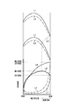
- FIG. 4 is an explanatory diagram showing changes in the airflow velocity from the leading edge to the trailing edge of the wing structure in the prior art.
- FIG. 5 is an explanatory diagram showing changes in the airflow velocity of the wing structure according to the present embodiment.
- this wing has a normal structure according to the prior art. That is, this wing is constituted by a single wing portion having a single wing structure and does not have a tandem wing portion.
- the solid line L1 indicates the back side of the wing
- the alternate long and short dash line L2 indicates the flank side of the wing
- the broken line L3 indicates the throat portion where the interval between adjacent wings is the narrowest.
- the horizontal axis indicates the axial position of the wing
- the vertical axis indicates the air velocity.
- the solid line L4 in the graph indicates the back side speed when the speed ratio is large
- the alternate long and short dash line L5 indicates the abdominal side speed when the speed ratio is large
- the solid line L6 indicates the back side speed when the speed ratio is small
- An alternate long and short dash line L7 indicates the speed on the ventral side when the speed ratio is small.
- the maximum speed (peak Mach number) on the back side of the blade is located at the trailing edge of the blade. In this case, since the exit speed is equal to the maximum speed, no deceleration region occurs.
- the speed ratio is small, as indicated by the solid line L6, the maximum speed on the back side of the wing is located in front of the trailing edge of the wing (position of the throat portion). Therefore, in this case, the exit speed is smaller than the maximum speed.
- tandem blade portions 1t and 2t are provided on the inner peripheral surface 31 side of the moving blade 1 and the outer peripheral surface 32 side of the stationary blade 2 having a small speed ratio. ing.
- the load in the deceleration region difference between the maximum speed and the outlet speed
- the front wings 12 and 22 and the rear wings 13 and 23 of the tandem wing parts 1t and 2t resulting in a decrease in efficiency and generation of a secondary flow. It is suppressed.
- the speed ratio is large on the outer peripheral surface 32 side of the moving blade 1 and the inner peripheral surface 31 side of the stationary blade 2, and a deceleration region that causes a reduction in efficiency is unlikely to occur. Therefore, when tandem blades are provided on the outer peripheral surface 32 side of the moving blade 1 and the inner peripheral surface 31 side of the stationary blade 2, the efficiency may decrease. Therefore, in the present embodiment, single blade portions 1s, 2s are provided on the outer peripheral surface 32 side of the moving blade 1 and the inner peripheral surface 31 side of the stationary blade 2, and tandem blade portions 1t, 2t are provided in the remaining portions. Yes.
- the tandem blade portions 1t and 2t and the single blade portions 1s and 2s are selectively used according to the change (size) of the speed ratio in the longitudinal direction of the moving blade 1 and the stationary blade 2. .
- This improves the efficiency of the blade as a whole and suppresses the generation of secondary flow.
- blade longitudinal direction is called a partial tandem wing
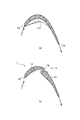
- FIG. 5 shows a change in the air velocity of the wing structure according to the present embodiment when the speed ratio is small.
- the solid line L8 is the back side of the front wing 12
- the alternate long and short dash line L9 is the ventral side of the front wing 12
- the solid line L10 is the back side of the rear wing 13
- the alternate long and short dash line L11 is the rear wing.
- the broken line L12 indicates the back side of the conventional wing
- the two-dot chain line L13 indicates the ventral side of the conventional wing
- the broken line L14 indicates the throat portion.
- the horizontal axis indicates the axial position of the wing
- the vertical axis indicates the air velocity.
- the solid line L15 in the graph is the speed on the back side of the front wing 12
- the dashed line L16 is the speed on the ventral side of the front wing 12
- the solid line L17 is the speed on the back side of the rear wing 13
- the dashed line L18 is the ventral side of the rear wing 13.
- the broken line L19 indicates the speed on the back side of the conventional wing
- the two-dot chain line L20 indicates the speed on the ventral side of the conventional wing.
- the rear edge of the front wing 12 and the front edge of the rear wing 13 are overlapped with each other in the direction of the air flow while being spaced apart in the direction perpendicular to the air current.
- a nozzle-shaped flow path Z is formed.
- the back side of the rear blade 13 of the moving blade 1 may be continuous with the back side of the single blade portion 1s. That is, at least a part of the back surface of the rear wing 13 may be smoothly connected to the back surface of the single wing portion 1s.
- the front blade 12 of the moving blade 1 may be inclined with respect to the single blade portion 1s.
- the back side of the rear blade 23 of the stationary blade 2 may be continuous with the back side of the single blade portion 2s. That is, at least a part of the back surface of the rear wing 23 may be smoothly connected to the back surface of the single wing portion 2s.
- the front blade 22 of the stationary blade 2 may be inclined with respect to the single blade portion 2s.
- the position of the throat portion T does not change from the single wing portions 1s, 2s to the tandem wing portions 1t, 2t. That is, a design change from a conventional wing having only a single wing portion to a partial tandem wing having tandem wing portions 1t and 2t is facilitated.
- the front wing 12 is inclined with respect to the single wing portion 1s, the front wing 12 is in a bow stacking state, and the flow at the longitudinal end portion of the front wing 12 follows the inclination.
- the secondary flow can be reduced by being guided to the center in the longitudinal direction of the front wing 12.
- FIG. 6 is an explanatory view showing one of the effects of the blade structure according to the present embodiment, where (a) is a sectional view of a conventional blade structure, and (b) is a sectional view of the blade structure according to the present embodiment.
- FIG. Thick arrows in the figure indicate the direction of airflow.
- the airflow flowing from the front edge LE of the front wing 12 to the ventral side is ejected from the rear edge TE of the front wing 12 to the back side.
- separation of the airflow flowing on the ventral side of the front wing 12 can be suppressed, and it is not necessary to increase the thickness of the front wing 12, and the weight of the wing can be reduced.
- the moving blade 1 and the stationary blade 2 are disposed in the flow path 3, and the moving blade 1 has the tandem blade portion 1 t formed on the radially inner surface 31 side of the flow path 3.
- the blade 2 has been illustrated and described with respect to the case where the tandem blade portion 2t is formed on the radially outer peripheral surface 32 side of the flow path 3, the present invention is not limited to the axial flow turbomachine having only the moving blade 1 or static
- the present invention can be applied to an axial flow turbomachine having only blades 2, and can be applied to only one of axial flow turbomachines having moving blades 1 and stationary blades 2.
- the present invention can also be applied to axial-flow turbomachines other than gas turbine engines.
Abstract
A vane structure for an axial flow turbomachine that has: a single-vane section (1s, 2s) that has a single-vane structure formed on a portion of the length of a vane; and a tandem-vane section (1t, 2t) that is formed continuing from the single-vane section (1s, 2s) in the remaining portion of the length of the vane and comprises a front vane (12, 22) and a rear vane (13, 23) that are respectively arranged on the upstream and downstream sides of a flow of air flowing through a flow path.
Description
本発明は、効率の改善を図った軸流ターボ機械の翼の構造及びガスタービンエンジンに関する。
The present invention relates to a blade structure of an axial-flow turbomachine and a gas turbine engine that are improved in efficiency.
軸流コンプレッサや軸流タービンなどの軸流ターボ機械は、軸方向に複数段配置した、複数の動翼を備えたローター及び複数の静翼を備えたステーターを備える。軸流ターボ機械は、例えば、航空機用のガスタービンエンジンにおいて、用いられることが多い。軸流ターボ機械の動翼又は静翼において、流れは翼の背側にて加速される。一般に、翼は、流れの速度が最大に達する位置(即ち、ピークマッハ数に達する位置)をできるだけ当該翼の後縁側に近付けるように設計される。仮に、最大速度に達する位置が翼の後縁であれば、流れが減速する領域は翼において存在しない。一方、最大速度に達する位置が翼の後縁よりも前方に位置する場合、その位置から翼の後縁までの間で気流が減速する。この場合、その減速領域によって剥離が生じて効率が低下したり、二次流れ(ガスの主流とは方向が異なる旋回成分を持つ流れ)が生じたりする可能性がある。
An axial flow turbomachine such as an axial flow compressor or an axial flow turbine includes a rotor including a plurality of moving blades and a stator including a plurality of stationary blades arranged in a plurality of stages in the axial direction. Axial turbomachines are often used, for example, in aircraft gas turbine engines. In a moving blade or stationary blade of an axial flow turbomachine, the flow is accelerated on the back side of the blade. In general, a blade is designed so that the position where the flow velocity reaches the maximum (that is, the position where the peak Mach number is reached) is as close as possible to the trailing edge side of the blade. If the position at which the maximum speed is reached is the trailing edge of the blade, there is no region where the flow slows down in the blade. On the other hand, when the position where the maximum speed is reached is located ahead of the trailing edge of the blade, the airflow is decelerated between that position and the trailing edge of the blade. In this case, separation may occur due to the deceleration region and efficiency may be reduced, or a secondary flow (a flow having a swirling component whose direction is different from that of the main gas flow) may occur.
特許文献1は、前翼と後翼とを組合せてなるタンデム翼から構成されたタンデム翼列を開示している。かかるタンデム翼列は、前翼の下面の後縁から後翼の上面に吹き上げる噴流を後翼の上面に沿って流れるように、噴流の速度及び運動量等を調整し、これにより後翼の上面の境界層の剥離を抑制している。
Patent Document 1 discloses a tandem cascade composed of tandem wings formed by combining a front wing and a rear wing. Such a tandem cascade adjusts the speed and momentum of the jet so that the jet that blows from the rear edge of the lower surface of the front wing to the upper surface of the rear wing flows along the upper surface of the rear wing. Boundary layer peeling is suppressed.
特許文献2は、タンデム動翼と、当該タンデム動翼の下流にあって前記タンデム動翼からの流れを所定角度に転向させるタンデム静翼と、を備えた圧縮機の構造を開示している。タンデム動翼及びタンデム静翼は、特許文献1と同様に、後翼の上面における境界層の剥離を抑制するように構成されている。特許文献2は、かかるタンデム動翼とタンデム静翼とを交互に多段に配置することによって、より少ない段数でより高圧力比を得ることを目的としている。
Patent Document 2 discloses a structure of a compressor including a tandem moving blade and a tandem stationary blade that is downstream of the tandem moving blade and turns the flow from the tandem moving blade to a predetermined angle. Similar to Patent Document 1, the tandem moving blade and the tandem stationary blade are configured to suppress separation of the boundary layer on the upper surface of the rear wing. Patent Document 2 aims to obtain a higher pressure ratio with a smaller number of stages by arranging such tandem moving blades and tandem stationary blades alternately in multiple stages.
動翼や静翼は、軸流ターボ機械の径方向に向けて放射状に配置されている。通常、各翼における翼長手方向の一端側の速度比と他端側の速度比とは異なる。ここで、速度比とは、翼の入口における流れの速度(入口速度)に対する当該翼の出口における速度(出口速度)の比である。つまり、速度比は出口速度を入口速度で除した値である。軸流ターボ機械の動翼及び静翼において、翼長手方向の一端側では速度比が大きい。従って、上述の最大速度の位置を後縁付近に設定することは比較的容易である。しかしながら、翼長手方向の他端側では速度比が上記一端側よりも相対的に小さい。従って、最大速度の位置が後縁よりも前方の位置になり易く、減速領域が生じてしまうという問題がある。
The moving blades and stationary blades are arranged radially in the radial direction of the axial flow turbomachine. Usually, the speed ratio on one end side in the blade longitudinal direction and the speed ratio on the other end side of each blade are different. Here, the speed ratio is the ratio of the speed (outlet speed) at the outlet of the blade to the flow speed (inlet speed) at the inlet of the blade. That is, the speed ratio is a value obtained by dividing the outlet speed by the inlet speed. In a moving blade and a stationary blade of an axial-flow turbomachine, the speed ratio is large at one end side in the blade longitudinal direction. Therefore, it is relatively easy to set the position of the maximum speed near the trailing edge. However, the speed ratio is relatively smaller on the other end side in the blade longitudinal direction than on the one end side. Therefore, there is a problem that the position of the maximum speed tends to be a position ahead of the rear edge, and a deceleration region is generated.
特許文献1や特許文献2に記載されたタンデム翼は、翼全体を前翼と後翼とに分離して、後翼の上面における境界層の剥離を抑制しようとするものである。しかしながら上述したように、翼長手方向の一端側と他端側とでは速度比が異なることから、翼長手方向の全域において均一の効果が得られる訳ではない。すなわち、速度比が大きな翼長手方向の一端側を基準にすれば、速度比が小さな翼長手方向の他端側の剥離を抑制することが困難になる。その逆に、速度比が小さな翼長手方向の他端側を基準にすれば、速度比が大きな翼長手方向の一端側における吹き出し力が強くなり過ぎてしまい二次流れを生じる原因となってしまう。
The tandem wing described in Patent Document 1 and Patent Document 2 attempts to suppress separation of the boundary layer on the upper surface of the rear wing by separating the entire wing into a front wing and a rear wing. However, as described above, since the speed ratio is different between the one end side and the other end side in the blade longitudinal direction, a uniform effect is not obtained in the entire region in the blade longitudinal direction. That is, if one end side in the blade longitudinal direction with a large speed ratio is used as a reference, it is difficult to suppress separation on the other end side in the blade longitudinal direction with a small speed ratio. Conversely, if the other end side in the blade longitudinal direction with a small speed ratio is used as a reference, the blowing force at one end side in the blade longitudinal direction with a large speed ratio becomes too strong, causing secondary flow. .
本発明は、以上の事情を鑑みて創案されたものであり、静翼又は動翼における後縁の減速領域を低減するとともに、二次流れの発生又は成長を抑制し、効率の向上を図ることができる、軸流ターボ機械の翼の構造及びガスタービンエンジンを提供することにある。
The present invention was devised in view of the above circumstances, and reduces the deceleration region of the trailing edge of a stationary blade or moving blade, suppresses the generation or growth of secondary flow, and improves efficiency. An object of the present invention is to provide an axial-flow turbomachine blade structure and a gas turbine engine that can perform the above-described operation.
本発明の第1の態様は、軸流ターボ機械の流路中に配置される動翼又は静翼として用いられる翼の構造であって、翼長手方向の一部に形成された一枚翼構造のシングル翼部と、前記シングル翼部に繋げて前記翼長手方向の残部に形成されたタンデム翼部であって、前記軸流ターボ機械を流れる気流において前方に配置された前翼及び後方に配置された後翼から成るタンデム翼部と、を有することを要旨とする。
1st aspect of this invention is the structure of the blade | wing used as a moving blade or a stationary blade arrange | positioned in the flow path of an axial-flow turbomachine, Comprising: The single blade structure formed in a part of blade longitudinal direction A single wing portion, a tandem wing portion connected to the single wing portion and formed in the remaining portion in the longitudinal direction of the wing, and disposed in the front and rear in the airflow flowing through the axial-flow turbomachine And a tandem wing part composed of a rear wing.
本発明の第2の態様はガスタービンエンジンであって、第1の態様に係る構造の翼を動翼又は静翼として含む軸流ターボ機械を備えることを要旨とする。
The gist of a second aspect of the present invention is a gas turbine engine, which includes an axial flow turbomachine including blades having the structure according to the first aspect as moving blades or stationary blades.
前記タンデム翼部は、翼長手方向の一端側及び他端側のうち速度比が小さい側に形成されていてもよい。前記シングル翼部は、前記翼長手方向の一端側及び他端側のうち速度比が大きい側に形成されていてもよい。
The tandem wing portion may be formed on the side having the smaller speed ratio among the one end side and the other end side in the blade longitudinal direction. The single wing portion may be formed on a side having a larger speed ratio among one end side and the other end side in the blade longitudinal direction.
前記タンデム翼部は、前記流路の径方向の内周面及び外周面のうち傾斜角度が大きい面に形成されていてもよい。前記シングル翼部は、前記流路の径方向の内周面及び外周面のうち傾斜角度が小さい面に形成されていてもよい。
The tandem wing portion may be formed on a surface having a large inclination angle among an inner peripheral surface and an outer peripheral surface in the radial direction of the flow path. The single wing portion may be formed on a surface having a small inclination angle among an inner peripheral surface and an outer peripheral surface in the radial direction of the flow path.
前記シングル翼部及び前記タンデム翼部は前記動翼を構成してもよい。この場合、前記タンデム翼部は、径方向における前記流路の内周面側に位置してもよい。
The single wing portion and the tandem wing portion may constitute the moving blade. In this case, the tandem wing portion may be located on the inner peripheral surface side of the flow path in the radial direction.
前記シングル翼部及び前記タンデム翼部は前記静翼を構成してもよい。この場合、前記タンデム翼部は、径方向における前記流路の内周面側又は外周面側に位置してもよい。
The single wing portion and the tandem wing portion may constitute the stationary blade. In this case, the tandem wing portion may be located on the inner peripheral surface side or the outer peripheral surface side of the flow path in the radial direction.
また、前記後翼の背側は、前記シングル翼部の背側に連続していてもよい。前記前翼は、前記シングル翼部に対して傾斜していてもよい。
Further, the back side of the rear wing may be continuous with the back side of the single wing part. The front wing may be inclined with respect to the single wing portion.
本発明に係る軸流ターボ機械の翼の構造及びガスタービンエンジンによれば、効率低下の原因となる翼後縁部分における減速領域の負荷を、タンデム翼の前翼と後翼とに分散させることができ、翼全体としての減速領域を低減することができ、効率の向上を図ることができる。
According to the structure of the blade of the axial-flow turbomachine and the gas turbine engine according to the present invention, the load in the deceleration region at the blade trailing edge that causes a reduction in efficiency is distributed to the front blade and the rear blade of the tandem blade. Thus, the deceleration area of the entire blade can be reduced, and the efficiency can be improved.
また、動翼又は静翼の一部に前翼と後翼とから成るタンデム翼部を形成したことにより、二次流れは後縁に向かって成長し易いところ、前翼の後縁部分で背側と腹側の静圧差を消失させることができ、二次流れを低減することができ、効率の向上を図ることができる。
In addition, by forming a tandem wing part consisting of a front wing and a rear wing on a part of a moving blade or stationary blade, the secondary flow tends to grow toward the rear edge. The static pressure difference between the side and the ventral side can be eliminated, the secondary flow can be reduced, and the efficiency can be improved.
以下に添付図面を参照しながら、本発明の一実施形態について詳細に説明する。かかる実施形態に示す寸法、材料、その他具体的な数値等は、発明の理解を容易にするための例示に過ぎず、特に断る場合を除き、本発明を限定するものではない。なお、本明細書及び図面において、実質的に同一の機能、構成を有する要素については、同一の符号を付すことにより重複した説明を省略し、また、本発明に直接関係のない要素は図示を省略する。
Hereinafter, an embodiment of the present invention will be described in detail with reference to the accompanying drawings. The dimensions, materials, and other specific numerical values shown in the embodiments are merely examples for facilitating understanding of the invention, and do not limit the present invention unless otherwise specified. In the present specification and drawings, elements having substantially the same function and configuration are denoted by the same reference numerals, and redundant description is omitted, and elements not directly related to the present invention are illustrated. Omitted.
図1に示したように、本実施形態に係るガスタービンエンジンは、複数の動翼1を備えたローター11と複数の静翼2を備えたステーター21とを有する。これら動翼1及び静翼2には、後述する軸流ターボ機械の翼構造が適用されている。ガスタービンエンジンは、例えば、ジェットエンジンであり、図示しないが、上流側から、吸気口、圧縮機、燃焼室、タービン、排気口を有している。図1のローター11及びステーター21は、タービンの一部として図示されている。なお、本実施形態に係る翼構造は、圧縮機の動翼及び静翼にも適用することができる。
As shown in FIG. 1, the gas turbine engine according to the present embodiment includes a rotor 11 having a plurality of moving blades 1 and a stator 21 having a plurality of stationary blades 2. A blade structure of an axial flow turbomachine, which will be described later, is applied to the moving blade 1 and the stationary blade 2. The gas turbine engine is, for example, a jet engine, and has an intake port, a compressor, a combustion chamber, a turbine, and an exhaust port from the upstream side (not shown). The rotor 11 and stator 21 of FIG. 1 are illustrated as part of the turbine. Note that the blade structure according to the present embodiment can also be applied to a moving blade and a stationary blade of a compressor.
タービンの流路3は、回転軸Lの周りに配される環状の断面を有し、略回転軸Lに沿って延伸している。流路3は、径方向内側に内周面31及び径方向外側に外周面32を有している。通常、径方向は翼長手方向と一致する。ローター11は、動翼1と、動翼1の根元部分を支持し、内周面31を構成するプラットホームとを備える。一方、ステーター21は、外周面32と、外周面32に固定(支持)された静翼2と、静翼2の径方向内側に設けられ、内周面31を構成するプラットホームとを備える。図1に示したように、動翼1及び静翼2のプラットホームは、全体として所定の形状の流路面(内周面31)を形成するように連続的に形成される。また、外周面32は、タービンの外周を覆うケーシングの一部を構成する。
The turbine flow path 3 has an annular cross section disposed around the rotation axis L and extends substantially along the rotation axis L. The flow path 3 has an inner peripheral surface 31 on the radially inner side and an outer peripheral surface 32 on the radially outer side. Usually, the radial direction coincides with the blade longitudinal direction. The rotor 11 includes a moving blade 1 and a platform that supports a root portion of the moving blade 1 and forms an inner peripheral surface 31. On the other hand, the stator 21 includes an outer circumferential surface 32, a stationary blade 2 fixed (supported) to the outer circumferential surface 32, and a platform that is provided on the radially inner side of the stationary blade 2 and constitutes the inner circumferential surface 31. As shown in FIG. 1, the platforms of the moving blade 1 and the stationary blade 2 are continuously formed so as to form a flow path surface (inner peripheral surface 31) having a predetermined shape as a whole. Moreover, the outer peripheral surface 32 comprises a part of casing which covers the outer periphery of a turbine.
図2(b)に示したように、動翼1は、翼長手方向の一部に形成されたシングル翼部1sと、シングル翼部1sに繋げて翼長手方向の残部に形成されたタンデム翼部1tと、を有している。
換言すると、シングル翼部1s及びタンデム翼部1tは翼長手方向に延伸する1つの翼本体を形成し、シングル翼部1sは翼長手方向における翼本体の一部に設けられ、タンデム翼部1tは翼長手方向における翼本体の残部に設けられる。さらに換言すると、動翼1は、翼長手方向に延伸するシングル翼部1sと、シングル翼部1sと翼長手方向に連結するタンデム翼部1tとを有している。図2(b)及び(c)に示したように、シングル翼部1sは一枚翼で構成された構造を有する。また、タンデム翼部1tは、タービン(すなわち、軸流ターボ機械)を流れる気流に対して前に配置された前翼12と、気流に対して後に配置された後翼13とから成る。換言すると、タンデム翼部1tは、タービンを流れる気流において前方に配置された前翼12及び後方に配置された後翼13から成る。 As shown in FIG. 2B, the movingblade 1 includes a single blade portion 1s formed in a part of the blade longitudinal direction, and a tandem blade formed in the remaining portion in the blade longitudinal direction connected to the single blade portion 1s. Part 1t.
In other words, thesingle wing portion 1s and the tandem wing portion 1t form one wing body extending in the wing longitudinal direction, and the single wing portion 1s is provided in a part of the wing body in the wing longitudinal direction. It is provided in the remaining part of the blade body in the blade longitudinal direction. In other words, the moving blade 1 has a single blade portion 1s extending in the blade longitudinal direction and a tandem blade portion 1t connected to the single blade portion 1s in the blade longitudinal direction. As shown in FIGS. 2B and 2C, the single wing portion 1s has a structure constituted by a single blade. The tandem blade portion 1t includes a front blade 12 disposed in front of an airflow flowing through a turbine (that is, an axial turbomachine) and a rear blade 13 disposed behind the airflow. In other words, the tandem wing portion 1t is composed of the front wing 12 disposed in the front and the rear wing 13 disposed in the rear in the airflow flowing through the turbine.
換言すると、シングル翼部1s及びタンデム翼部1tは翼長手方向に延伸する1つの翼本体を形成し、シングル翼部1sは翼長手方向における翼本体の一部に設けられ、タンデム翼部1tは翼長手方向における翼本体の残部に設けられる。さらに換言すると、動翼1は、翼長手方向に延伸するシングル翼部1sと、シングル翼部1sと翼長手方向に連結するタンデム翼部1tとを有している。図2(b)及び(c)に示したように、シングル翼部1sは一枚翼で構成された構造を有する。また、タンデム翼部1tは、タービン(すなわち、軸流ターボ機械)を流れる気流に対して前に配置された前翼12と、気流に対して後に配置された後翼13とから成る。換言すると、タンデム翼部1tは、タービンを流れる気流において前方に配置された前翼12及び後方に配置された後翼13から成る。 As shown in FIG. 2B, the moving
In other words, the
図2(a)に示したように、静翼2も、翼長手方向の一部に形成されたシングル翼部2sと、シングル翼部2sに繋げて翼長手方向の残部に形成されたタンデム翼部2tと、を有している。換言すると、シングル翼部2s及びタンデム翼部2tは翼長手方向に延伸する1つの翼本体を形成し、シングル翼部2sは翼長手方向における翼本体の一部に設けられ、タンデム翼部2tは翼長手方向における翼本体の残部に設けられる。さらに換言すると、静翼2は、翼長手方向に延伸するシングル翼部2sと、シングル翼部2sと翼長手方向に連結するタンデム翼部2tとを有している。シングル翼部1sと同様に、シングル翼部2sは一枚翼で構成された構造を有する。また、タンデム翼部2tは、動翼1のタンデム翼部1tと同様に、タービン(すなわち、軸流ターボ機械)を流れる気流に対して前に配置された前翼22と、気流に対して後に配置された後翼23とから成る。換言すると、タンデム翼部2tは、タービンを流れる気流において前方に配置された前翼22及び後方に配置された後翼23から成る。
As shown in FIG. 2A, the stationary blade 2 also includes a single blade portion 2s formed in a part of the blade longitudinal direction, and a tandem blade formed in the remaining portion in the blade longitudinal direction connected to the single blade portion 2s. Part 2t. In other words, the single wing portion 2s and the tandem wing portion 2t form one wing body extending in the wing longitudinal direction, the single wing portion 2s is provided in a part of the wing body in the wing longitudinal direction, and the tandem wing portion 2t is It is provided in the remaining part of the blade body in the blade longitudinal direction. In other words, the stationary blade 2 has a single blade portion 2s extending in the blade longitudinal direction, and a tandem blade portion 2t connected to the single blade portion 2s in the blade longitudinal direction. Similar to the single wing portion 1s, the single wing portion 2s has a structure constituted by a single blade. Further, the tandem wing part 2t, like the tandem wing part 1t of the moving blade 1, has a front wing 22 disposed in front of the airflow flowing through the turbine (that is, the axial flow turbomachine) and a rearward of the airflow. The rear wing 23 is arranged. In other words, the tandem blade portion 2t includes the front blade 22 disposed in the front and the rear blade 23 disposed rearward in the airflow flowing through the turbine.
図1における破線は、タンデム翼部1t,2tが形成されている部分を示している。この図に示すように、本実施形態の動翼1では、流路3の内周面31側にタンデム翼部1tが形成され、流路3の外周面32側にシングル翼部1sが形成されている。また、本実施形態の静翼2では、流路3の外周面32側にタンデム翼部2tが形成され、流路3の内周面31側にシングル翼部2sが形成されている。すなわち、径方向(翼長手方向)におけるシングル翼部1s,2sとタンデム翼部1t,2tの配置(配列)が、動翼1と静翼2とで逆転している。
The broken lines in FIG. 1 indicate the portions where the tandem wing portions 1t and 2t are formed. As shown in this figure, in the moving blade 1 of the present embodiment, a tandem blade portion 1t is formed on the inner peripheral surface 31 side of the flow path 3, and a single blade portion 1s is formed on the outer peripheral surface 32 side of the flow path 3. ing. Further, in the stationary blade 2 of the present embodiment, the tandem blade portion 2 t is formed on the outer peripheral surface 32 side of the flow channel 3, and the single blade portion 2 s is formed on the inner peripheral surface 31 side of the flow channel 3. That is, the arrangement (arrangement) of the single blade portions 1s, 2s and the tandem blade portions 1t, 2t in the radial direction (blade longitudinal direction) is reversed between the moving blade 1 and the stationary blade 2.
図3は、動翼及び静翼における径方向(翼長手方向)の位置に応じた速度比の変化を示す説明図である。横軸は、速度比(出口速度/入口速度)を示し、縦軸は、径方向の位置を示している。図中の実線は、動翼1の速度比を示し、一点鎖線は静翼2の速度比を示している。
FIG. 3 is an explanatory view showing a change in speed ratio according to the radial position (blade longitudinal direction) of the moving blade and the stationary blade. The horizontal axis indicates the speed ratio (exit speed / inlet speed), and the vertical axis indicates the radial position. The solid line in the figure indicates the speed ratio of the moving blade 1, and the alternate long and short dash line indicates the speed ratio of the stationary blade 2.
図3に示したように、動翼1(図1参照)における速度比は、翼長手方向(タービンの径方向)の内側(内周面31側)の方が外側(外周面32側)よりも小さい。一方、静翼2(図1参照)における速度比は、翼長手方向(タービンの径方向)の外側(外周面32側)の方が内側(内周面31側)よりも小さい。ここで、動翼1のタンデム翼部1t及び静翼2のタンデム翼部2tは、図中の破線で囲んだ範囲に形成されている。すなわち、動翼1のタンデム翼部1t及び静翼2のタンデム翼部2tは、翼長手方向の一端側及び他端側のうち速度比が小さい側に形成されている。また、動翼1のシングル翼部1s及び静翼2のシングル翼部2sは、翼長手方向の一端側及び他端側のうち速度比が大きい側に形成されている。
As shown in FIG. 3, the speed ratio of the moving blade 1 (see FIG. 1) is such that the inner side (inner peripheral surface 31 side) in the blade longitudinal direction (turbine radial direction) is more outer than the outer side (outer peripheral surface 32 side). Is also small. On the other hand, the speed ratio in the stationary blade 2 (see FIG. 1) is smaller on the outer side (outer peripheral surface 32 side) in the blade longitudinal direction (turbine radial direction) than on the inner side (inner peripheral surface 31 side). Here, the tandem blade portion 1t of the moving blade 1 and the tandem blade portion 2t of the stationary blade 2 are formed in a range surrounded by a broken line in the figure. That is, the tandem wing part 1t of the moving blade 1 and the tandem wing part 2t of the stationary blade 2 are formed on the side having the smaller speed ratio among the one end side and the other end side in the blade longitudinal direction. Moreover, the single blade part 1s of the moving blade 1 and the single blade part 2s of the stationary blade 2 are formed on the side having the larger speed ratio among the one end side and the other end side in the blade longitudinal direction.
上述の通り、動翼1における外周面32側の速度比が、内周面31側の速度比よりも大きい。これは、動翼1の外周面32側の周速(周方向速度)が内周面31側の周速(周方向速度)よりも大きいからである。詳述すると、動翼1の入口における流入速度(すなわち、前段の静翼2の出口における後段の動翼1への流入速度)は、内周面31側よりも外周面32側の方が小さい。加えて、外周面32側の周速は内周面31側の周速よりも大きい。そのため、相対流入速度に換算した場合は、外周面32側が内周面31側よりも益々小さくなる。一方、相対出口速度は内周面31側も外周面32側も略同じ大きさである。従って、動翼1の速度比は外周面32側が内周面31側よりも大きくなる。
As described above, the speed ratio on the outer peripheral surface 32 side of the rotor blade 1 is larger than the speed ratio on the inner peripheral surface 31 side. This is because the peripheral speed (circumferential speed) on the outer peripheral surface 32 side of the rotor blade 1 is larger than the peripheral speed (circumferential speed) on the inner peripheral surface 31 side. More specifically, the inflow speed at the inlet of the moving blade 1 (that is, the inflow speed to the subsequent moving blade 1 at the outlet of the preceding stationary blade 2) is smaller on the outer peripheral surface 32 side than on the inner peripheral surface 31 side. . In addition, the peripheral speed on the outer peripheral surface 32 side is larger than the peripheral speed on the inner peripheral surface 31 side. Therefore, when converted into a relative inflow velocity, the outer peripheral surface 32 side becomes smaller than the inner peripheral surface 31 side. On the other hand, the relative outlet speed is substantially the same on both the inner peripheral surface 31 side and the outer peripheral surface 32 side. Accordingly, the speed ratio of the moving blade 1 is larger on the outer peripheral surface 32 side than on the inner peripheral surface 31 side.
また、静翼2における外周面32側の速度比が、内周面31側の速度比よりも小さい。これは、図1に示したように、内周面31側と比較して、流路3の外周面32側が流れ方向に沿って拡大していることによってディフューザー効果が現れ、このディフューザー効果によって外周面32側での気流の加速が内周面31側に比べて抑制されるからである。ここで、内周面31の軸方向に対する傾斜角度をα、外周面32の軸方向に対する傾斜角度をβとすると、図1に示した流路3では、傾斜角度βは傾斜角度αよりも大きい。したがって、静翼2のタンデム翼部2tは、流路3の径方向の内周面31及び外周面32のうち傾斜角度が大きい面に形成されていると言い換えることもできる。同様に、静翼2のシングル翼部2sは、流路3の径方向の内周面31及び外周面32のうち傾斜角度が小さい面に形成されていると言い換えることもできる。
Also, the speed ratio on the outer peripheral surface 32 side of the stationary blade 2 is smaller than the speed ratio on the inner peripheral surface 31 side. As shown in FIG. 1, the diffuser effect appears by expanding the outer peripheral surface 32 side of the flow path 3 along the flow direction as compared with the inner peripheral surface 31 side. This is because the acceleration of the airflow on the surface 32 side is suppressed compared to the inner peripheral surface 31 side. Here, if the inclination angle with respect to the axial direction of the inner peripheral surface 31 is α and the inclination angle with respect to the axial direction of the outer peripheral surface 32 is β, the inclination angle β is larger than the inclination angle α in the flow path 3 shown in FIG. . Accordingly, it can be said that the tandem blade portion 2t of the stationary blade 2 is formed on a surface having a large inclination angle among the inner circumferential surface 31 and the outer circumferential surface 32 in the radial direction of the flow path 3. Similarly, it can be said that the single blade portion 2 s of the stationary blade 2 is formed on a surface having a small inclination angle among the inner circumferential surface 31 and the outer circumferential surface 32 in the radial direction of the flow path 3.
なお、図1に示した実施形態では、傾斜角度βが傾斜角度αよりも大きい。しかしながら、この大小関係は図1に示す実施形態に限定されない。例えば、傾斜角度αは傾斜角度βよりも大きくてもよい。或いは、流路3の軸方向の一部のみで傾斜角度βが傾斜角度αよりも大きくてもよい。
In the embodiment shown in FIG. 1, the inclination angle β is larger than the inclination angle α. However, this magnitude relationship is not limited to the embodiment shown in FIG. For example, the inclination angle α may be larger than the inclination angle β. Alternatively, the inclination angle β may be larger than the inclination angle α in only a part of the flow path 3 in the axial direction.
静翼2において、タンデム翼部2tを翼長手方向の一端側及び他端側のうち速度比が小さい側に形成するか、流路3の径方向の内周面31及び外周面32のうち傾斜角度が大きい側に形成するか、については、両者の気流に与える影響の度合を考慮して選択することができる。その結果、静翼2のタンデム翼部2tは、流路3の径方向の内周面31側に形成される場合もあるし、外周面32側に形成される場合もある。
In the stationary blade 2, the tandem blade portion 2 t is formed on one of the one end side and the other end side in the blade longitudinal direction where the speed ratio is small, or the inner circumferential surface 31 and the outer circumferential surface 32 in the radial direction of the flow path 3 are inclined. Whether the angle is formed on the larger side can be selected in consideration of the degree of influence on both airflows. As a result, the tandem blade portion 2t of the stationary blade 2 may be formed on the inner peripheral surface 31 side in the radial direction of the flow path 3 or may be formed on the outer peripheral surface 32 side.
次に、上述した本実施形態に係る軸流ターボ機械の翼の構造の作用について説明する。図4は、従来技術における翼の構造の前縁から後縁にかけての気流速度の変化を示す説明図である。図5は、本実施形態に係る翼の構造の気流速度の変化を示す説明図である。
Next, the operation of the blade structure of the axial-flow turbomachine according to this embodiment described above will be described. FIG. 4 is an explanatory diagram showing changes in the airflow velocity from the leading edge to the trailing edge of the wing structure in the prior art. FIG. 5 is an explanatory diagram showing changes in the airflow velocity of the wing structure according to the present embodiment.
図4に示した翼は従来技術による通常の構造を有する。即ち、この翼は一枚翼構造のシングル翼部によって構成され、タンデム翼部を有しない。図4の上段に示した翼の断面図において、実線L1は翼の背側、一点鎖線L2は翼の腹側、破線L3は隣接する翼同士の間隔が最も狭くなるスロート部を示している。
4 has a normal structure according to the prior art. That is, this wing is constituted by a single wing portion having a single wing structure and does not have a tandem wing portion. In the cross-sectional view of the wing shown in the upper part of FIG. 4, the solid line L1 indicates the back side of the wing, the alternate long and short dash line L2 indicates the flank side of the wing, and the broken line L3 indicates the throat portion where the interval between adjacent wings is the narrowest.
また、図4の下段に示したグラフにおいて、横軸は翼の軸方向位置を示し、縦軸は気流速度を示している。また、グラフ中の実線L4は速度比が大きい場合の背側の速度、一点鎖線L5は速度比が大きい場合の腹側の速度を示し、実線L6は速度比が小さい場合の背側の速度、一点鎖線L7は速度比が小さい場合の腹側の速度を示している。
In the graph shown in the lower part of FIG. 4, the horizontal axis indicates the axial position of the wing, and the vertical axis indicates the air velocity. Also, the solid line L4 in the graph indicates the back side speed when the speed ratio is large, the alternate long and short dash line L5 indicates the abdominal side speed when the speed ratio is large, and the solid line L6 indicates the back side speed when the speed ratio is small, An alternate long and short dash line L7 indicates the speed on the ventral side when the speed ratio is small.
速度比が大きい場合には、実線L4で示したように、翼の背側における最大速度(ピークマッハ数)は翼の後縁に位置する。この場合、出口速度は最大速度と等しいため、減速領域は生じない。一方、速度比が小さい場合には、実線L6で示したように、翼の背側における最大速度は翼の後縁よりも前方(スロート部の位置)に位置する。従って、この場合、出口速度は最大速度よりも小さくなる。このため、速度比が小さい場合には、翼の背側において、最大速度に達する位置と後縁との間に減速領域が生じ、減速領域は効率の低下や二次流れの発生を誘引する。
When the speed ratio is large, as indicated by the solid line L4, the maximum speed (peak Mach number) on the back side of the blade is located at the trailing edge of the blade. In this case, since the exit speed is equal to the maximum speed, no deceleration region occurs. On the other hand, when the speed ratio is small, as indicated by the solid line L6, the maximum speed on the back side of the wing is located in front of the trailing edge of the wing (position of the throat portion). Therefore, in this case, the exit speed is smaller than the maximum speed. For this reason, when the speed ratio is small, a deceleration region occurs between the position where the maximum speed is reached and the trailing edge on the back side of the blade, and the deceleration region induces a decrease in efficiency and the generation of a secondary flow.
そこで、本実施形態においては、図1~図3に示したように、速度比が小さな動翼1の内周面31側及び静翼2の外周面32側にタンデム翼部1t,2tを設けている。これにより、減速領域の負荷(最大速度と出口速度の差)がタンデム翼部1t,2tの前翼12,22と後翼13,23とに分散し、効率の低下及び二次流れの発生が抑制される。
Therefore, in the present embodiment, as shown in FIGS. 1 to 3, tandem blade portions 1t and 2t are provided on the inner peripheral surface 31 side of the moving blade 1 and the outer peripheral surface 32 side of the stationary blade 2 having a small speed ratio. ing. As a result, the load in the deceleration region (difference between the maximum speed and the outlet speed) is distributed to the front wings 12 and 22 and the rear wings 13 and 23 of the tandem wing parts 1t and 2t, resulting in a decrease in efficiency and generation of a secondary flow. It is suppressed.
また、動翼1の外周面32側及び静翼2の内周面31側では速度比が大きく、効率低下の要因となる減速領域が生じ難い。従って、動翼1の外周面32側及び静翼2の内周面31側にタンデム翼を設けた場合は、却って効率が低下する可能性がある。そこで、本実施形態では、動翼1の外周面32側及び静翼2の内周面31側にシングル翼部1s,2sが設けられ、残りの部分にタンデム翼部1t,2tが設けられている。
Also, the speed ratio is large on the outer peripheral surface 32 side of the moving blade 1 and the inner peripheral surface 31 side of the stationary blade 2, and a deceleration region that causes a reduction in efficiency is unlikely to occur. Therefore, when tandem blades are provided on the outer peripheral surface 32 side of the moving blade 1 and the inner peripheral surface 31 side of the stationary blade 2, the efficiency may decrease. Therefore, in the present embodiment, single blade portions 1s, 2s are provided on the outer peripheral surface 32 side of the moving blade 1 and the inner peripheral surface 31 side of the stationary blade 2, and tandem blade portions 1t, 2t are provided in the remaining portions. Yes.
つまり、本実施形態では、動翼1及び静翼2の翼長手方向における速度比の変化(大きさ)に応じて、タンデム翼部1t,2tとシングル翼部1s,2sとが使い分けられている。これにおり、翼全体としての効率が向上し、且つ、二次流れの発生が抑制される。なお、翼長手方向の一部にタンデム翼部1t,2tを有する翼は、例えば、パーシャルタンデム翼と称される。
That is, in the present embodiment, the tandem blade portions 1t and 2t and the single blade portions 1s and 2s are selectively used according to the change (size) of the speed ratio in the longitudinal direction of the moving blade 1 and the stationary blade 2. . This improves the efficiency of the blade as a whole and suppresses the generation of secondary flow. In addition, the wing | blade which has tandem wing | blade part 1t, 2t in a part of wing | blade longitudinal direction is called a partial tandem wing | blade, for example.
図5は、速度比が小さい場合における、本実施形態に係る翼の構造の気流速度の変化を示している。図5の上段に示した翼の断面図において、実線L8は前翼12の背側、一点鎖線L9は前翼12の腹側、実線L10は後翼13の背側、一点鎖線L11は後翼13の腹側を示し、破線L12は従来の翼の背側、二点鎖線L13は従来の翼の腹側を示し、破線L14はスロート部を示している。
FIG. 5 shows a change in the air velocity of the wing structure according to the present embodiment when the speed ratio is small. 5, the solid line L8 is the back side of the front wing 12, the alternate long and short dash line L9 is the ventral side of the front wing 12, the solid line L10 is the back side of the rear wing 13, and the alternate long and short dash line L11 is the rear wing. 13, the broken line L12 indicates the back side of the conventional wing, the two-dot chain line L13 indicates the ventral side of the conventional wing, and the broken line L14 indicates the throat portion.
また、図5の下段に示したグラフは、横軸が翼における軸方向の位置を示し、縦軸が気流速度を示している。グラフ中の実線L15は前翼12の背側の速度、一点鎖線L16は前翼12の腹側の速度、実線L17は後翼13の背側の速度、一点鎖線L18は後翼13の腹側の速度を示し、破線L19は従来の翼の背側の速度、二点鎖線L20は従来の翼の腹側の速度を示している。
In the graph shown in the lower part of FIG. 5, the horizontal axis indicates the axial position of the wing, and the vertical axis indicates the air velocity. The solid line L15 in the graph is the speed on the back side of the front wing 12, the dashed line L16 is the speed on the ventral side of the front wing 12, the solid line L17 is the speed on the back side of the rear wing 13, and the dashed line L18 is the ventral side of the rear wing 13. The broken line L19 indicates the speed on the back side of the conventional wing, and the two-dot chain line L20 indicates the speed on the ventral side of the conventional wing.
図5に示したように、動翼1の速度比が小さい部分にタンデム翼部1tを適用することで、従来の翼の構造の場合に減速領域にて生じる減速負荷(最大速度と出口速度の差:減速量)が前翼12と後翼13とに分散され、低減される。したがって、減速負荷と相関する効率が向上する。また、前翼12の背側の気流と腹側の気流とが前翼12の後縁にて繋がり、翼間の静圧の差を前翼12で一旦消失させることができる。これにより、二次流れの発生及び成長を抑制することができる。なお、図5では動翼1の作用について説明したが、静翼2の作用についても同様のものが得られる。
As shown in FIG. 5, by applying the tandem blade portion 1t to a portion where the speed ratio of the moving blade 1 is small, a deceleration load (maximum speed and outlet speed) generated in the deceleration region in the case of the conventional blade structure. (Difference: deceleration amount) is distributed to the front wing 12 and the rear wing 13 and reduced. Therefore, the efficiency correlated with the deceleration load is improved. Further, the airflow on the back side of the front wing 12 and the airflow on the abdomen side are connected at the rear edge of the front wing 12, and the difference in static pressure between the wings can be temporarily eliminated by the front wing 12. Thereby, generation | occurrence | production and growth of a secondary flow can be suppressed. In addition, although the effect | action of the moving blade 1 was demonstrated in FIG. 5, the same thing is obtained also about the effect | action of the stationary blade 2. FIG.
また、図5に示したように、前翼12の後縁と後翼13の前縁とが、気流の直交方向に間隔を隔てつつ、気流の方向に重なり合っている。この部分には、ノズル状の流路Zが形成される。流路Zは、前翼12の腹側の流れが流路Zを通過する際にその流れを加速し、後翼13の背側に供給する。従って、後翼13の背側の境界層厚さを薄くすることができ、翼の性能を向上させることができる。
Further, as shown in FIG. 5, the rear edge of the front wing 12 and the front edge of the rear wing 13 are overlapped with each other in the direction of the air flow while being spaced apart in the direction perpendicular to the air current. In this portion, a nozzle-shaped flow path Z is formed. When the flow on the ventral side of the front wing 12 passes through the flow path Z, the flow path Z accelerates the flow and supplies it to the back side of the rear wing 13. Therefore, the thickness of the boundary layer on the back side of the rear wing 13 can be reduced, and the performance of the wing can be improved.
すなわち、流路Zによって加速された気流を後翼13の背側に吹き付けることで、後翼13の背側における層流から乱流への境界層遷移時に発生する剥離渦の発生を抑制することができ、翼素性能を向上させることができる。なお、これについては、静翼2のタンデム翼部2tでも同様のものが得られる。
That is, by blowing the airflow accelerated by the flow path Z to the back side of the rear wing 13, the generation of separation vortices generated at the boundary layer transition from laminar flow to turbulent flow on the back side of the rear wing 13 is suppressed. The blade element performance can be improved. In addition, the same thing is obtained also about the tandem blade part 2t of the stationary blade 2 about this.
図2(a)及び(b)に示したように、動翼1の後翼13の背側は、シングル翼部1sの背側と連続していてもよい。すなわち、後翼13の背面の少なくとも一部は、シングル翼部1sの背面と滑らかに接続していてもよい。また、動翼1の前翼12は、シングル翼部1sに対して傾斜していてもよい。同様に、静翼2の後翼23の背側は、シングル翼部2sの背側と連続していてもよい。すなわち、後翼23の背面の少なくとも一部は、シングル翼部2sの背面と滑らかに接続していてもよい。また、静翼2の前翼22は、シングル翼部2sに対して傾斜していてもよい。かかる構成により、スロート部Tの位置は、シングル翼部1s,2sからタンデム翼部1t,2tにかけて変化しない。すなわち、シングル翼部のみからなる従来の翼から、タンデム翼部1t,2tを有するパーシャルタンデム翼への設計変更が容易になる。
2A and 2B, the back side of the rear blade 13 of the moving blade 1 may be continuous with the back side of the single blade portion 1s. That is, at least a part of the back surface of the rear wing 13 may be smoothly connected to the back surface of the single wing portion 1s. Further, the front blade 12 of the moving blade 1 may be inclined with respect to the single blade portion 1s. Similarly, the back side of the rear blade 23 of the stationary blade 2 may be continuous with the back side of the single blade portion 2s. That is, at least a part of the back surface of the rear wing 23 may be smoothly connected to the back surface of the single wing portion 2s. Further, the front blade 22 of the stationary blade 2 may be inclined with respect to the single blade portion 2s. With this configuration, the position of the throat portion T does not change from the single wing portions 1s, 2s to the tandem wing portions 1t, 2t. That is, a design change from a conventional wing having only a single wing portion to a partial tandem wing having tandem wing portions 1t and 2t is facilitated.
また、前翼12がシングル翼部1sに対して傾斜しているので、前翼12がボウ・スタッキング(Bow stacking)された状態となり、前翼12の翼長手方向端部の流れが傾斜に沿って前翼12の翼長手方向中央に導かれ、二次流れを低減することができる。
Further, since the front wing 12 is inclined with respect to the single wing portion 1s, the front wing 12 is in a bow stacking state, and the flow at the longitudinal end portion of the front wing 12 follows the inclination. Thus, the secondary flow can be reduced by being guided to the center in the longitudinal direction of the front wing 12.
ここで、図6は、本実施形態に係る翼構造の効果の一つを示す説明図であり、(a)は従来の翼構造断面図、(b)は本実施形態に係る翼構造の断面図、を示している。図中の太矢印は、気流の方向を示している。
Here, FIG. 6 is an explanatory view showing one of the effects of the blade structure according to the present embodiment, where (a) is a sectional view of a conventional blade structure, and (b) is a sectional view of the blade structure according to the present embodiment. FIG. Thick arrows in the figure indicate the direction of airflow.
図6(a)に示した従来の翼構造においては、一枚の翼で気流の向きを入口の矢印から出口の矢印の方向に大きく変更していることから、翼の前縁LEの腹側で剥離が生じ易く、これが二次流れを生じる要因にもなっていた。そこで、従来の翼構造では、剥離領域を低減するために、腹側の翼形状を一点鎖線L21で示したように厚肉化する対策が取られることが多く、重量の増加を招いていた。
In the conventional wing structure shown in FIG. 6 (a), the direction of the airflow is greatly changed from the entrance arrow to the exit arrow direction with a single wing, so that the ventral side of the leading edge LE of the wing In this case, peeling was likely to occur, and this was a factor causing secondary flow. Therefore, in the conventional wing structure, in order to reduce the separation region, a measure to increase the thickness of the wing shape on the ventral side as indicated by the alternate long and short dash line L21 is often taken, resulting in an increase in weight.
一方、図6(b)に示した本実施形態では、前翼12の前縁LEから腹側に流れる気流は前翼12の後縁TEから背側に噴き出されることから、従来の翼構造と比較して、前翼12の腹側に流れる気流の剥離を抑制することができ、前翼12を厚肉化する必要がなく、翼の軽量化を図ることができる。
On the other hand, in the present embodiment shown in FIG. 6B, the airflow flowing from the front edge LE of the front wing 12 to the ventral side is ejected from the rear edge TE of the front wing 12 to the back side. In comparison with the above, separation of the airflow flowing on the ventral side of the front wing 12 can be suppressed, and it is not necessary to increase the thickness of the front wing 12, and the weight of the wing can be reduced.
以上、添付図面を参照しつつ本発明の好適な実施形態について説明したが、本発明は上述した各実施形態に限定されないことは勿論であり、特許請求の範囲に記載された範疇における各種の変更例又は修正例についても、本発明の技術的範囲に属することは言うまでもない。
The preferred embodiments of the present invention have been described above with reference to the accompanying drawings. However, the present invention is not limited to the above-described embodiments, and various modifications within the scope of the claims. Needless to say, examples and modifications also belong to the technical scope of the present invention.
例えば、上述した実施形態では、流路3中に動翼1及び静翼2が配置され、動翼1は流路3の径方向の内周面31側にタンデム翼部1tが形成され、静翼2は流路3の径方向の外周面32側にタンデム翼部2tが形成されている場合について、図示して説明したが、本発明は、動翼1のみを有する軸流ターボ機械や静翼2のみを有する軸流ターボ機械にも適用することができるし、動翼1及び静翼2を有する軸流ターボ機械においていずれか一方にのみ適用することもできる。また、本発明は、ガスタービンエンジン以外の軸流ターボ機械にも適用することができる。
For example, in the above-described embodiment, the movingblade 1 and the stationary blade 2 are disposed in the flow path 3, and the moving blade 1 has the tandem blade portion 1 t formed on the radially inner surface 31 side of the flow path 3. Although the blade 2 has been illustrated and described with respect to the case where the tandem blade portion 2t is formed on the radially outer peripheral surface 32 side of the flow path 3, the present invention is not limited to the axial flow turbomachine having only the moving blade 1 or static The present invention can be applied to an axial flow turbomachine having only blades 2, and can be applied to only one of axial flow turbomachines having moving blades 1 and stationary blades 2. The present invention can also be applied to axial-flow turbomachines other than gas turbine engines.
For example, in the above-described embodiment, the moving
Claims (7)
- 軸流ターボ機械の流路中に配置される動翼又は静翼として用いられる翼の構造であって、
翼長手方向の一部に形成された一枚翼構造のシングル翼部と、
前記シングル翼部に繋げて前記翼長手方向の残部に形成されたタンデム翼部であって、前記軸流ターボ機械を流れる気流において前方に配置された前翼及び後方に配置された後翼から成るタンデム翼部と、
を有することを特徴とする軸流ターボ機械の翼の構造。 A structure of a blade used as a moving blade or a stationary blade disposed in a flow path of an axial-flow turbomachine,
A single wing part of a single wing structure formed in a part of the wing longitudinal direction;
A tandem wing part connected to the single wing part and formed in the remaining part in the longitudinal direction of the wing, comprising a front wing arranged forward and a rear wing arranged rearward in the airflow flowing through the axial-flow turbomachine Tandem wings,
A structure of a blade of an axial-flow turbomachine characterized by comprising: - 前記タンデム翼部は、前記翼長手方向の一端側及び他端側のうち速度比が小さい側に形成され、
前記シングル翼部は、前記翼長手方向の一端側及び他端側のうち速度比が大きい側に形成されていることを特徴とする請求項1に記載の軸流ターボ機械の翼の構造。 The tandem wing part is formed on the side where the speed ratio is small among the one end side and the other end side in the blade longitudinal direction,
2. The structure of an axial-flow turbomachine blade according to claim 1, wherein the single blade portion is formed on a side having a larger speed ratio among one end side and the other end side in the blade longitudinal direction. - 前記タンデム翼部は、径方向における前記流路の内周面及び外周面のうち傾斜角度が大きい面に形成され、
前記シングル翼部は、径方向における前記流路の前記内周面及び前記外周面のうち傾斜角度が小さい面に形成されていることを特徴とする請求項1に記載の軸流ターボ機械の翼の構造。 The tandem wing portion is formed on a surface having a large inclination angle among the inner peripheral surface and the outer peripheral surface of the flow path in the radial direction,
2. The blade of an axial-flow turbomachine according to claim 1, wherein the single blade portion is formed on a surface having a small inclination angle among the inner peripheral surface and the outer peripheral surface of the flow path in the radial direction. Structure. - 前記シングル翼部及び前記タンデム翼部は前記動翼を構成し、
前記タンデム翼部は、径方向における前記流路の内周面側に位置することを特徴とする請求項1に記載の軸流ターボ機械の翼の構造。 The single wing portion and the tandem wing portion constitute the moving blade,
2. The structure of an axial-flow turbomachine blade according to claim 1, wherein the tandem blade portion is located on an inner peripheral surface side of the flow path in a radial direction. - 前記シングル翼部及び前記タンデム翼部は前記静翼を構成し、
前記タンデム翼部は、径方向における前記流路の内周面側又は外周面側に位置することを特徴とする請求項1に記載の軸流ターボ機械の翼の構造。 The single wing portion and the tandem wing portion constitute the stationary blade,
2. The structure of an axial-flow turbomachine blade according to claim 1, wherein the tandem blade portion is located on an inner peripheral surface side or an outer peripheral surface side of the flow path in a radial direction. - 前記後翼の背側は、前記シングル翼部の背側に連続しており、
前記前翼は、前記シングル翼部に対して傾斜していることを特徴とする請求項1から5の何れか1項に記載の軸流ターボ機械の翼の構造。 The back side of the rear wing is continuous with the back side of the single wing,
6. The structure of an axial-flow turbomachine blade according to claim 1, wherein the front blade is inclined with respect to the single blade portion. - 請求項1から6の何れか1項に記載の構造の翼を動翼又は静翼として含む軸流ターボ機械を備えることを特徴とするガスタービンエンジン。
A gas turbine engine comprising an axial-flow turbomachine including the blade having the structure according to any one of claims 1 to 6 as a moving blade or a stationary blade.
Priority Applications (3)
| Application Number | Priority Date | Filing Date | Title |
|---|---|---|---|
| EP14862038.8A EP3070264A4 (en) | 2013-11-15 | 2014-10-10 | Vane structure for axial flow turbomachine and gas turbine engine |
| JP2015547691A JP6194960B2 (en) | 2013-11-15 | 2014-10-10 | Axial turbomachine blade structure and gas turbine engine |
| US15/058,393 US20160177728A1 (en) | 2013-11-15 | 2016-03-02 | Vane structure for axial flow turbomachine and gas turbine engine |
Applications Claiming Priority (2)
| Application Number | Priority Date | Filing Date | Title |
|---|---|---|---|
| JP2013-236476 | 2013-11-15 | ||
| JP2013236476 | 2013-11-15 |
Related Child Applications (1)
| Application Number | Title | Priority Date | Filing Date |
|---|---|---|---|
| US15/058,393 Continuation US20160177728A1 (en) | 2013-11-15 | 2016-03-02 | Vane structure for axial flow turbomachine and gas turbine engine |
Publications (1)
| Publication Number | Publication Date |
|---|---|
| WO2015072256A1 true WO2015072256A1 (en) | 2015-05-21 |
Family
ID=53057198
Family Applications (1)
| Application Number | Title | Priority Date | Filing Date |
|---|---|---|---|
| PCT/JP2014/077151 WO2015072256A1 (en) | 2013-11-15 | 2014-10-10 | Vane structure for axial flow turbomachine and gas turbine engine |
Country Status (4)
| Country | Link |
|---|---|
| US (1) | US20160177728A1 (en) |
| EP (1) | EP3070264A4 (en) |
| JP (1) | JP6194960B2 (en) |
| WO (1) | WO2015072256A1 (en) |
Cited By (3)
| Publication number | Priority date | Publication date | Assignee | Title |
|---|---|---|---|---|
| EP3255244A1 (en) * | 2016-05-20 | 2017-12-13 | United Technologies Corporation | Tandem tip blades and corresponding gas turbine engine |
| WO2019111973A1 (en) * | 2017-12-05 | 2019-06-13 | 株式会社富士通ゼネラル | Propeller fan |
| US10500683B2 (en) | 2016-07-22 | 2019-12-10 | Rolls-Royce Deutschland Ltd & Co Kg | Methods of manufacturing a tandem guide vane segment |
Families Citing this family (4)
| Publication number | Priority date | Publication date | Assignee | Title |
|---|---|---|---|---|
| EP2977549B1 (en) * | 2014-07-22 | 2017-05-31 | Safran Aero Boosters SA | Axial turbomachine blading and corresponding turbomachine |
| US10695704B2 (en) * | 2016-07-20 | 2020-06-30 | General Electric Company | Multi-station debris separation system |
| CN113803274B (en) * | 2021-11-19 | 2022-03-04 | 中国航发上海商用航空发动机制造有限责任公司 | Axial compressor and turbofan engine |
| BE1030421B1 (en) * | 2022-04-05 | 2023-10-30 | Safran Aero Boosters | TANDEM STATOR |
Citations (4)
| Publication number | Priority date | Publication date | Assignee | Title |
|---|---|---|---|---|
| GB2106193A (en) * | 1981-09-24 | 1983-04-07 | Rolls Royce | Turbomachine rotor blade |
| JPH07279887A (en) * | 1994-04-15 | 1995-10-27 | Ishikawajima Harima Heavy Ind Co Ltd | Axial flow air compressor |
| JPH1122486A (en) | 1997-06-30 | 1999-01-26 | Kawasaki Heavy Ind Ltd | Compressor structure using tandem blade |
| JP2954539B2 (en) | 1996-08-09 | 1999-09-27 | 川崎重工業株式会社 | Tandem cascade |
Family Cites Families (5)
| Publication number | Priority date | Publication date | Assignee | Title |
|---|---|---|---|---|
| DE2515444B2 (en) * | 1975-04-09 | 1977-05-18 | Maschinenfabrik Augsburg-Nürnberg AG, 8500 Nürnberg | LARGE CIRCLING SPEED FOR THERMAL, AXIAL-FLOW TURBINES |
| US5277549A (en) * | 1992-03-16 | 1994-01-11 | Westinghouse Electric Corp. | Controlled reaction L-2R steam turbine blade |
| ITBA20030052A1 (en) * | 2003-10-17 | 2005-04-18 | Paolo Pietricola | ROTORIC AND STATHIC POLES WITH MULTIPLE PROFILES |
| DE102007024840A1 (en) * | 2007-05-29 | 2008-12-04 | Rolls-Royce Deutschland Ltd & Co Kg | Turbomachinery bucket with multi-profile design |
| DE102010053798A1 (en) * | 2010-12-08 | 2012-06-14 | Rolls-Royce Deutschland Ltd & Co Kg | Turbomachine - blade with hybrid tread design |
-
2014
- 2014-10-10 WO PCT/JP2014/077151 patent/WO2015072256A1/en active Application Filing
- 2014-10-10 EP EP14862038.8A patent/EP3070264A4/en not_active Withdrawn
- 2014-10-10 JP JP2015547691A patent/JP6194960B2/en active Active
-
2016
- 2016-03-02 US US15/058,393 patent/US20160177728A1/en not_active Abandoned
Patent Citations (4)
| Publication number | Priority date | Publication date | Assignee | Title |
|---|---|---|---|---|
| GB2106193A (en) * | 1981-09-24 | 1983-04-07 | Rolls Royce | Turbomachine rotor blade |
| JPH07279887A (en) * | 1994-04-15 | 1995-10-27 | Ishikawajima Harima Heavy Ind Co Ltd | Axial flow air compressor |
| JP2954539B2 (en) | 1996-08-09 | 1999-09-27 | 川崎重工業株式会社 | Tandem cascade |
| JPH1122486A (en) | 1997-06-30 | 1999-01-26 | Kawasaki Heavy Ind Ltd | Compressor structure using tandem blade |
Non-Patent Citations (1)
| Title |
|---|
| See also references of EP3070264A4 * |
Cited By (7)
| Publication number | Priority date | Publication date | Assignee | Title |
|---|---|---|---|---|
| EP3255244A1 (en) * | 2016-05-20 | 2017-12-13 | United Technologies Corporation | Tandem tip blades and corresponding gas turbine engine |
| US10151322B2 (en) | 2016-05-20 | 2018-12-11 | United Technologies Corporation | Tandem tip blade |
| US10500683B2 (en) | 2016-07-22 | 2019-12-10 | Rolls-Royce Deutschland Ltd & Co Kg | Methods of manufacturing a tandem guide vane segment |
| US11278992B2 (en) | 2016-07-22 | 2022-03-22 | Rolls-Royce Deutschland Ltd & Co Kg | Methods of manufacturing a tandem guide vane segment |
| WO2019111973A1 (en) * | 2017-12-05 | 2019-06-13 | 株式会社富士通ゼネラル | Propeller fan |
| AU2018381395B2 (en) * | 2017-12-05 | 2021-09-23 | Fujitsu General Limited | Propeller fan |
| US11187237B2 (en) | 2017-12-05 | 2021-11-30 | Fujitsu General Limited | Propeller fan |
Also Published As
| Publication number | Publication date |
|---|---|
| EP3070264A4 (en) | 2017-06-21 |
| JP6194960B2 (en) | 2017-09-13 |
| EP3070264A1 (en) | 2016-09-21 |
| JPWO2015072256A1 (en) | 2017-03-16 |
| US20160177728A1 (en) | 2016-06-23 |
Similar Documents
| Publication | Publication Date | Title |
|---|---|---|
| JP6194960B2 (en) | Axial turbomachine blade structure and gas turbine engine | |
| EP3502416B1 (en) | Inlet guide vane and corresponding gas turbine engine | |
| JP5092143B2 (en) | High bypass ratio turbofan jet engine | |
| US8696306B2 (en) | Bypass duct of a turbofan engine | |
| US9726197B2 (en) | Turbomachine element | |
| US8882461B2 (en) | Gas turbine engines with improved trailing edge cooling arrangements | |
| EP3176442B1 (en) | Axial flow device with casing treatment and jet engine | |
| EP3483395B1 (en) | Inter-turbine ducts with flow control mechanisms | |
| US11486254B2 (en) | Boundary layer ingestion fan system | |
| US11629664B2 (en) | Turbine engine with a flow splitter having a profile with inclined serrations | |
| CN104837726A (en) | Propeller blade for turbomachine | |
| US10519976B2 (en) | Fluid diodes with ridges to control boundary layer in axial compressor stator vane | |
| EP3098383B1 (en) | Compressor airfoil with compound leading edge profile | |
| JP2017078413A (en) | Aircraft engine spinner improved in crosswind performance | |
| WO2016080025A1 (en) | Axial-flow-machine blade | |
| US20180334921A1 (en) | Stator arrangement | |
| EP2778346B1 (en) | Rotor for a gas turbine engine, corresponding gas turbine engine and method of improving gas turbine engine rotor efficiency | |
| US20210270137A1 (en) | Turbine engine with airfoil having high acceleration and low blade turning | |
| US10287987B2 (en) | Noise reducing vane | |
| JP7294528B2 (en) | Stator blades and aircraft gas turbine engines | |
| RU2784237C2 (en) | Gas turbine engine with coaxial screws | |
| US11486253B2 (en) | Boundary layer ingestion fan system | |
| US20230073422A1 (en) | Stator with depressions in gaspath wall adjacent trailing edges | |
| EP2918777B1 (en) | Method for optimizing a vane to reduce noise |
Legal Events
| Date | Code | Title | Description |
|---|---|---|---|
| 121 | Ep: the epo has been informed by wipo that ep was designated in this application |
Ref document number: 14862038 Country of ref document: EP Kind code of ref document: A1 |
|
| ENP | Entry into the national phase |
Ref document number: 2015547691 Country of ref document: JP Kind code of ref document: A |
|
| REEP | Request for entry into the european phase |
Ref document number: 2014862038 Country of ref document: EP |
|
| NENP | Non-entry into the national phase |
Ref country code: DE |