EP3483395B1 - Inter-turbine ducts with flow control mechanisms - Google Patents
Inter-turbine ducts with flow control mechanisms Download PDFInfo
- Publication number
- EP3483395B1 EP3483395B1 EP18204762.1A EP18204762A EP3483395B1 EP 3483395 B1 EP3483395 B1 EP 3483395B1 EP 18204762 A EP18204762 A EP 18204762A EP 3483395 B1 EP3483395 B1 EP 3483395B1
- Authority
- EP
- European Patent Office
- Prior art keywords
- turbine
- inter
- splitter blade
- vortex generating
- duct
- Prior art date
- Legal status (The legal status is an assumption and is not a legal conclusion. Google has not performed a legal analysis and makes no representation as to the accuracy of the status listed.)
- Active
Links
- 230000007246 mechanism Effects 0.000 title description 4
- 239000003570 air Substances 0.000 description 29
- 238000000926 separation method Methods 0.000 description 27
- 239000007789 gas Substances 0.000 description 17
- 230000004323 axial length Effects 0.000 description 8
- 230000007704 transition Effects 0.000 description 8
- 238000011144 upstream manufacturing Methods 0.000 description 5
- 230000003247 decreasing effect Effects 0.000 description 3
- 238000004458 analytical method Methods 0.000 description 2
- 239000000567 combustion gas Substances 0.000 description 2
- 239000012530 fluid Substances 0.000 description 2
- 239000000446 fuel Substances 0.000 description 2
- 238000000034 method Methods 0.000 description 2
- 230000001737 promoting effect Effects 0.000 description 2
- 230000000630 rising effect Effects 0.000 description 2
- 230000002411 adverse Effects 0.000 description 1
- 239000012080 ambient air Substances 0.000 description 1
- 230000003321 amplification Effects 0.000 description 1
- 230000008901 benefit Effects 0.000 description 1
- 230000015572 biosynthetic process Effects 0.000 description 1
- 238000002485 combustion reaction Methods 0.000 description 1
- 238000004891 communication Methods 0.000 description 1
- 230000000295 complement effect Effects 0.000 description 1
- 230000008878 coupling Effects 0.000 description 1
- 238000010168 coupling process Methods 0.000 description 1
- 238000005859 coupling reaction Methods 0.000 description 1
- 230000007423 decrease Effects 0.000 description 1
- 230000001419 dependent effect Effects 0.000 description 1
- 238000009434 installation Methods 0.000 description 1
- 230000001788 irregular Effects 0.000 description 1
- 230000003137 locomotive effect Effects 0.000 description 1
- 238000003199 nucleic acid amplification method Methods 0.000 description 1
- 230000037361 pathway Effects 0.000 description 1
- 238000010248 power generation Methods 0.000 description 1
- 230000002265 prevention Effects 0.000 description 1
- 230000009467 reduction Effects 0.000 description 1
- 230000004044 response Effects 0.000 description 1
- 238000004904 shortening Methods 0.000 description 1
- XLYOFNOQVPJJNP-UHFFFAOYSA-N water Substances O XLYOFNOQVPJJNP-UHFFFAOYSA-N 0.000 description 1
- 208000016261 weight loss Diseases 0.000 description 1
Images


Classifications
-
- F—MECHANICAL ENGINEERING; LIGHTING; HEATING; WEAPONS; BLASTING
- F01—MACHINES OR ENGINES IN GENERAL; ENGINE PLANTS IN GENERAL; STEAM ENGINES
- F01D—NON-POSITIVE DISPLACEMENT MACHINES OR ENGINES, e.g. STEAM TURBINES
- F01D9/00—Stators
- F01D9/02—Nozzles; Nozzle boxes; Stator blades; Guide conduits, e.g. individual nozzles
- F01D9/04—Nozzles; Nozzle boxes; Stator blades; Guide conduits, e.g. individual nozzles forming ring or sector
- F01D9/041—Nozzles; Nozzle boxes; Stator blades; Guide conduits, e.g. individual nozzles forming ring or sector using blades
-
- F—MECHANICAL ENGINEERING; LIGHTING; HEATING; WEAPONS; BLASTING
- F01—MACHINES OR ENGINES IN GENERAL; ENGINE PLANTS IN GENERAL; STEAM ENGINES
- F01D—NON-POSITIVE DISPLACEMENT MACHINES OR ENGINES, e.g. STEAM TURBINES
- F01D5/00—Blades; Blade-carrying members; Heating, heat-insulating, cooling or antivibration means on the blades or the members
- F01D5/12—Blades
- F01D5/14—Form or construction
- F01D5/141—Shape, i.e. outer, aerodynamic form
- F01D5/145—Means for influencing boundary layers or secondary circulations
-
- F—MECHANICAL ENGINEERING; LIGHTING; HEATING; WEAPONS; BLASTING
- F01—MACHINES OR ENGINES IN GENERAL; ENGINE PLANTS IN GENERAL; STEAM ENGINES
- F01D—NON-POSITIVE DISPLACEMENT MACHINES OR ENGINES, e.g. STEAM TURBINES
- F01D9/00—Stators
- F01D9/02—Nozzles; Nozzle boxes; Stator blades; Guide conduits, e.g. individual nozzles
- F01D9/04—Nozzles; Nozzle boxes; Stator blades; Guide conduits, e.g. individual nozzles forming ring or sector
-
- F—MECHANICAL ENGINEERING; LIGHTING; HEATING; WEAPONS; BLASTING
- F01—MACHINES OR ENGINES IN GENERAL; ENGINE PLANTS IN GENERAL; STEAM ENGINES
- F01D—NON-POSITIVE DISPLACEMENT MACHINES OR ENGINES, e.g. STEAM TURBINES
- F01D25/00—Component parts, details, or accessories, not provided for in, or of interest apart from, other groups
- F01D25/28—Supporting or mounting arrangements, e.g. for turbine casing
-
- F—MECHANICAL ENGINEERING; LIGHTING; HEATING; WEAPONS; BLASTING
- F05—INDEXING SCHEMES RELATING TO ENGINES OR PUMPS IN VARIOUS SUBCLASSES OF CLASSES F01-F04
- F05D—INDEXING SCHEME FOR ASPECTS RELATING TO NON-POSITIVE-DISPLACEMENT MACHINES OR ENGINES, GAS-TURBINES OR JET-PROPULSION PLANTS
- F05D2220/00—Application
- F05D2220/30—Application in turbines
- F05D2220/32—Application in turbines in gas turbines
-
- F—MECHANICAL ENGINEERING; LIGHTING; HEATING; WEAPONS; BLASTING
- F05—INDEXING SCHEMES RELATING TO ENGINES OR PUMPS IN VARIOUS SUBCLASSES OF CLASSES F01-F04
- F05D—INDEXING SCHEME FOR ASPECTS RELATING TO NON-POSITIVE-DISPLACEMENT MACHINES OR ENGINES, GAS-TURBINES OR JET-PROPULSION PLANTS
- F05D2240/00—Components
- F05D2240/10—Stators
- F05D2240/12—Fluid guiding means, e.g. vanes
- F05D2240/124—Fluid guiding means, e.g. vanes related to the suction side of a stator vane
-
- F—MECHANICAL ENGINEERING; LIGHTING; HEATING; WEAPONS; BLASTING
- F05—INDEXING SCHEMES RELATING TO ENGINES OR PUMPS IN VARIOUS SUBCLASSES OF CLASSES F01-F04
- F05D—INDEXING SCHEME FOR ASPECTS RELATING TO NON-POSITIVE-DISPLACEMENT MACHINES OR ENGINES, GAS-TURBINES OR JET-PROPULSION PLANTS
- F05D2240/00—Components
- F05D2240/10—Stators
- F05D2240/12—Fluid guiding means, e.g. vanes
- F05D2240/127—Vortex generators, turbulators, or the like, for mixing
-
- F—MECHANICAL ENGINEERING; LIGHTING; HEATING; WEAPONS; BLASTING
- F05—INDEXING SCHEMES RELATING TO ENGINES OR PUMPS IN VARIOUS SUBCLASSES OF CLASSES F01-F04
- F05D—INDEXING SCHEME FOR ASPECTS RELATING TO NON-POSITIVE-DISPLACEMENT MACHINES OR ENGINES, GAS-TURBINES OR JET-PROPULSION PLANTS
- F05D2250/00—Geometry
- F05D2250/10—Two-dimensional
- F05D2250/13—Two-dimensional trapezoidal
Definitions
- the present invention generally relates to gas turbine engines, to inter-turbine ducts between the turbines of gas turbine engines, and more particularly to a turbine section of a gas turbine engine.
- a gas turbine engine may be used to power various types of vehicles and systems.
- a gas turbine engine may include, for example, five major sections: a fan section, a compressor section, a combustor section, a turbine section, and an exhaust nozzle section.
- the fan section induces air from the surrounding environment into the engine and accelerates a fraction of this air toward the compressor section. The remaining fraction of air induced into the fan section is accelerated through a bypass plenum and exhausted.
- the compressor section raises the pressure of the air it receives from the fan section and directs the compressed air into the combustor section where it is mixed with fuel and ignited.
- the high-energy combustion products then flow into and through the turbine section, thereby causing rotationally mounted turbine blades to rotate and generate energy.
- the air exiting the turbine section is exhausted from the engine through the exhaust section.
- the turbine section is implemented with one or more annular turbines, such as a high pressure turbine and a low pressure turbine.
- the high pressure turbine may be positioned upstream of the low pressure turbine and configured to drive a high pressure compressor, while the low pressure turbine is configured to drive a low pressure compressor and a fan.
- the high pressure and low pressure turbines have optimal operating speeds, and thus, optimal radial diameters that are different from one another. Because of this difference in radial size, an inter-turbine duct is arranged to fluidly couple the outlet of the high pressure turbine to inlet of the low pressure turbine and to transition between the changes in radius. It is advantageous from a weight and efficiency perspective to have a relatively short inter-turbine duct.
- inter-turbine ducts are designed with a compromise between the overall size and issues with boundary separation.
- some conventional gas turbine engines may be designed with elongated inter-turbine ducts or inter-turbine ducts that do not achieve the optimal size ratio between the high pressure turbine and the low pressure turbine.
- US20150300253A1 discloses a transition duct defining an airflow pathway between a low pressure compressor and a high pressure compressor of a gas turbine engine.
- the transition duct may comprise an inner wall and an outer wall located radially outward of the inner wall with respect to a central axis of the gas turbine engine. It may further comprise a first bend configured to turn the airflow radially inward with respect to the central axis, and a turning vane located at the first bend between the inner wall and the outer wall. The turning vane may be configured to assist the first bend in turning the airflow radially inward.
- EP2554793 discloses a transition duct with a splitter blade.
- US3578264 discloses boundary layer control for delay or prevention of flow separation and/or increase in rate of heat exchange between a surface and a fluid by an arrangement of surface elements which may take the form of either crests or discreet concave depressions in the surface, having effective depths or dimensions of less that of the adjacent boundary layer thickness, to cause the formation of vortices with succeeded surface elements being positioned to cause vortex amplification, for effective boundary layer mixing with less drag, weight penalty, noise, and energy loss than that of conventional vane-type generators.
- a turbine section of a gas turbine engine is provided according to claim 1.
- the inter-turbine duct is positioned between a high pressure turbine with a relatively small radial diameter and a low pressure turbine with a relatively large radial diameter.
- the inter-turbine duct may be defined by a shroud forming an outer boundary and a hub forming an inner boundary.
- the inter-turbine duct may further include one or more splitter blades positioned at particular radial distances that prevent and/or mitigate boundary separation of the air flow from the shroud and other surfaces as the air flow transitions in a radial direction.
- Each splitter blade may include one or more vortex generating structures on the suction side to prevent and/or mitigate boundary separation of the air flow from the splitter blade. Improvements in boundary separation along the shroud and along the splitter blade enable shorter inter-turbine ducts, and as such, improvements in weight and efficiency.
- FIG. 1 a schematic cross-sectional view of a gas turbine engine 100 in accordance with an exemplary embodiment.
- the engine 100 may be an annular structure about a longitudinal or axial centerline axis 102.
- axial refers broadly to a direction parallel to the axis 102 about which the rotating components of the engine 100 rotate. This axis 102 runs from the front of the engine 100 to the back of the engine 100.
- radial refers broadly to a direction that is perpendicular to the axis 102 and that points towards or away from the axis of the engine 100.
- a "circumferential" direction at a given point is a direction that is normal to the local radial direction and normal to the axial direction.
- axial-circumferential plane generally refers to the plane formed by the axial and circumferential directions
- axial-radial plane generally refers to the plane formed by the axial and radial directions.
- An “upstream” direction refers to the direction from which the local flow is coming
- a “downstream” direction refers to the direction in which the local flow is traveling.
- upstream direction will generally refer to a forward direction
- downstream direction will refer to a rearward direction.
- the engine 100 generally includes, in serial flow communication, a fan section 110, a low pressure compressor 120, a high pressure compressor 130, a combustor 140, and a turbine section 150, which may include a high pressure turbine 160 and a low pressure turbine 170.
- a fan section 110 During operation, ambient air enters the engine 100 at the fan section 110, which directs the air into the compressors 120 and 130.
- the compressors 120 and 130 provide compressed air to the combustor 140 in which the compressed air is mixed with fuel and ignited to generate hot combustion gases.
- the combustion gases pass through the high pressure turbine 160 and the low pressure turbine 170.
- an inter-turbine duct 180 couples the high pressure turbine 160 to the low pressure turbine 170.
- the high pressure turbine 160 and low pressure turbine 170 are used to provide thrust via the expulsion of the exhaust gases, to provide mechanical power by rotating a shaft connected to one of the turbines, or to provide a combination of thrust and mechanical power.
- the engine 100 is a multi-spool engine in which the high pressure turbine 160 drives the high pressure compressor 130 and the low pressure turbine 170 drives the low pressure compressor 120 and fan section 110.
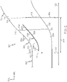
- FIG. 2 is a schematic, partial cross-sectional view of a turbine assembly with an inter-turbine duct, such as the inter-turbine duct 180 of the turbine section 150 of the engine 100 of FIG. 1 in accordance with an exemplary embodiment.
- the turbine section 150 includes the high pressure turbine 160, the low pressure turbine 170, and the inter-turbine duct 180 fluidly coupling the high pressure turbine 160 to the low pressure turbine 170.
- the inter-turbine duct 180 includes an inlet 202 coupled to the outlet 162 of the high pressure turbine 160 and an outlet 204 coupled to the inlet 172 of the low pressure turbine 170.
- the boundaries between the high pressure turbine 160 and the inter-turbine duct 180 and between the inter-turbine duct 180 and the low pressure turbine 170 are indicated by dashed lines 164, 174, respectively.
- the annular structure of the inter-turbine duct 180 is defined by a hub 210 and a shroud 220 to create a flow path 230 for air flow between the high pressure turbine 160 and low pressure turbine 170.
- the inter-turbine duct 180 transitions from a first radial diameter 250 at the inlet 202 (e.g., corresponding to the radial diameter at the outlet 162 of the high pressure turbine 160) to a larger, second radial diameter 252 (e.g., corresponding to the radial diameter at the inlet 172 of the low pressure turbine 170).
- the radial diameters are measured from the mid-point of the inter-turbine duct 180 although such diameters may also be measured from the hub 210 and/or the shroud 220. This transition is provided over an axial length 254.
- the inlet 202 may be generally axial from the high pressure turbine 160, and at inflection points 212, 222, the hub 210 and shroud 220 extend at an angle 256 to the outlet 204.
- FIG. 2 illustrates the angle 256 as being generally straight and constant, but other shapes may be provided, including constantly changing or stepped changes in radial diameter. In one exemplary embodiment, the angle 256 may be 30° or larger.
- a shorter axial length 254 may reduce the overall axial length of the engine 100 ( FIG. 1 ) as well as reducing friction losses of the air flow.
- the inter-turbine duct 180 functions to direct the air flow along the radial transition between turbines 160, 170. It is generally advantageous for the air flow to flow smoothly through the inter-turbine duct 180. Particularly, it is advantageous if the air flow adjacent to the shroud 220 maintains a path along the shroud 220 instead of undergoing a boundary layer separation. However, as the axial length 254 decreases and the angle 256 increases, the air flow along the shroud 220 tends to maintain an axial momentum through the inlet 202 and, if not addressed, attempts to separate from the shroud 220, particularly near or downstream the inflection point 222. Such separations may result in unwanted vortices or other turbulence that result in undesirable pressure losses through the inter-turbine duct 180 as well as inefficiencies in the low pressure turbine 170.
- one or more splitter blades 260 are provided within the inter-turbine duct 180 to prevent or mitigate the air flow separation.
- the splitter blade 260 may be referred to as a splitters or guide vane.
- one splitter blade 260 is illustrated in FIG. 2 , and typically only one splitter blade 260 with the features described below is necessary to achieve desired results. However, in other embodiments, additional splitter blades may be provided.
- the splitter blade 260 generally extends in an axial-circumferential plane, axisymmetric about the axis 102 and has an upstream end 262 and a downstream end 284.
- the upstream end 262 of the splitter blade 260 is positioned at, or immediately proximate to, the inlet 202 of the inter-turbine duct 180, and the downstream end 264 of the splitter blade 260 are positioned at, or immediately proximate to, the outlet 204 of the inter-turbine duct 180.
- the splitter blade 260 extends along approximately the entire axial length 254 of the inter-turbine duct 180.
- Other embodiments may have different arrangements, including different lengths and/or different axial positions.
- the splitter blade may be relatively shorter than that depicted in FIG. 2 based on, in some cases, the length associated with a desired reduction of flow separation and minimization of loss, while avoiding unnecessary weight and cost.
- the splitter blade 260 may be considered to have a pressure side 266 and a suction side 268.
- the pressure side 266 faces the shroud 220, and the suction side 268 faces the hub 210. Additional details about the suction side 268 of the splitter blade 260 are provided below.
- the splitter blade 260 may have characteristics to prevent flow separation.
- the splitter blade 260 may be radially positioned to advantageously prevent or mitigate flow separation.
- the radial positions may be a function of the radial distance or span of the inter-turbine duct 180 between hub 210 and shroud 220. For example, if the overall span is considered 100% with the shroud 220 being 0% and the hub 210 being 100%, the splitter blade 260 may be positioned at approximately 33% (e.g., approximately a third of the distance between the shroud 220 and the hub 210), 50%, or other radial positions.
- the splitter blade 260 may be supported in the inter-turbine duct 180 in various ways.
- the splitter blade 260 may be supported by one or more struts 290 that extend generally in the radial direction to secure the splitter blades 260 to the shroud 220 and/or hub 210.
- one or more struts 290 extend from the shroud 220 to support the splitter blade 260.
- the splitter blade 260 may be annular and continuous about the axis 102, although in other embodiments, the splitter blade 260 may be in sections or panels.
- FIG. 3 is a schematic pressure side (or top) view of the splitter blade 260 in the turbine section 150 of FIG. 2 .
- the shape and size of the splitter blade 260 may be selected based on computational fluid dynamics (CFD) analysis of various flow rates through the inter-turbine duct 180 and/or weight, installation, cost or efficiency considerations.
- CFD computational fluid dynamics
- the splitter blade 260 may also have a radial component.
- the splitter blade 260 is generally parallel to the shroud 220, although other shapes and arrangements may be provided.
- the splitter blade 260 may be parallel to a positional or weighted mean line curve that is a function of the shroud 220 and hub 210.
- the radial diameter along axial positions along a mean line curve may be defined by ((1-x%)(D_Shroud)+((x%)(D_Hub), thereby enabling a splitter blade 260 that is generally parallel to the selected mean line curve.
- the splitter blade 260 prevents or mitigates flow separation by guiding the air flow towards the shroud 220 or otherwise confining the flow along the shroud 220.
- flow separation may occur on the splitter blade 260.
- the splitter blade 260 may include one or more flow control mechanisms to prevent and/or mitigate flow separation as the air flows around the splitter blade 260, particularly flow separation on the suction side (or underside) 268 of the splitter blade 260.
- FIG. 4 is a schematic isometric suction side view of the splitter blade 260 of FIG. 2 in accordance with an exemplary embodiment which does not fall under the scope of the appended claims.
- the view of FIG. 4 is from the underside of the splitter blade 260. Since the potential separation on the suction side 268 is small than the potential separation on the shroud 220, the turbulent micro-vortices generated by the vortex generating structures 400 sufficiently energize the boundary layer flow without additional components, e.g., without additional splitter blades.
- multiple splitter blades may be provided with one or more of the blades having vortex generating structure 400 on the respective suction side.
- one or more vortex generating structures 400 are arranged on the suction side 268 of the splitter blade 260 as flow control mechanisms.
- the vortex generating structures 400 may be any structure that creates turbulent flow along the surface of the splitter blade 260.
- the vortex generating structures 400 function to energize a boundary layer flow by promoting mixing of the air flowing over the splitter blade with the core flow, which encourages smooth flow over the splitter blade 260 and mitigates or prevents flow separation from the suction side 268 of the splitter blade 260.
- the vortex generating structures 400 may be considered micro vortex generators.
- the vortex generating structures 400 may have various types of individual and collective characteristics.
- the vortex generating structures 400 are arranged to generate a series of counter-rotating vortices 408.
- the vortex generating structures 400 may have any suitable shape, and each structure 400 may further be considered to have a leading end 410, a trailing end 412, a length 414 along the surface of the splitter blade 260, and a height 416 from the surface of the splitter blade 260.
- the vane generating structures 400 may be trapezoidal such that the leading end 410 may be angled, e.g., increasing or rising in height 416 along the length 414 from the leading end 410 and plateauing in height to the trailing end 412.
- An angle of the leading end 410 from the surface of the suction side 268 may be considered the rise angle.
- the rise angle may be approximately 10° to approximately 90° relative to the surface of the suction side 268.
- the terminus of trailing end 412 may extend perpendicularly relative to the surface of the splitter blade 260.
- any shape may be provided.
- the vortex generating structures 400 may be triangular, square-shaped, or irregular.
- the vortex generating structures 400 are arranged in pairs 402, e.g., with a first vortex generating structure 404 and a second vortex generating structure 406, and the pairs are arranged in a circumferential row.
- the count (or number) of the vortex generating structures 400 in the circumferential row may vary, for example, approximately 25 to approximately 1000. In one embodiment, the count is approximately 75 to approximately 250. Although a single row is depicted in FIG. 4 , multiple rows may be provided.
- each structure 404, 406 of a respective pair 402 may be angled relative to one another and relative to the flow direction.
- structure 404 may be oriented at a first angle 420 relative to the flow direction
- structure 406 may be oriented at a second angle 422 relative to the flow direction.
- the first angle 420 is approximately 2° to approximately 30°.
- the second angle 422 may be supplementary to one another, e.g., the angles 420, 422 sum to 180°.
- the second angle 422 may be approximately 150° to 178°.
- the angles 420, 422 may be non-complementary.
- the paired vortex generating structures 400 are non-parallel, e.g., with different first and second angles 420, 422.
- the first angle 420 may be less than 90° and the second angle 422 may be greater than 90° such that the paired vortex generating structures 400 are oriented such that the trailing ends 412 diverge or generally point away from one another (and the leading ends 410 point towards one another.
- the vortex generating structures 400 are paired and angled to produce counter-rotating vortices 408.
- the counter-rotating vortices provide the desired energy characteristics to mix the air flowing along the suction side 268 with the core flow flowing through the duct.
- the vortex generating structures 400 may be considered to have a forward surface that at least partially faces the oncoming flow and an opposite aft surface.
- the vortices 408 may be most pronounced from the trailing ends 412 of the structures 400.
- the vortices 408 tend to result from air flow striking the forward surface, flowing along the forward surface, and curling around the trailing end 412 towards the aft surfaces. Since the paired vortex generating structures 400 have different orientations and are generally non-parallel, the resulting adjacent vortices 408 may be counter-rotating relative to one another.
- the structures 400 within a pair and relative to adjacent pairs may have any suitable spacing.
- the structures 404, 406 may be spaced such that the leading ends 410 are separated by a gap distance 426.
- the gap distances 426 may be sized such that the vortices generated by the structures 404, 406 are appropriately positioned and have the desired characteristics.
- the structures 404, 406 may have a length 414 and gap distances 426 such that vortices 408 at the trailing ends 412 of the array of vortex generating structures 400 are appropriately placed and sized.
- the gap distances 426 may be approximately 2 mm to approximately 10 mm.
- the length 414 and height 416 of the vortex generating structures 400 may also influence the vortex characteristics.
- the length 414 may be approximately 10 mm to approximately 50 mm.
- the height 416 may be approximately 1 mm to approximately 20 mm. In particular, the height 416 may be approximately 2 mm to approximately 5 mm.
- FIG. 5 is a schematic isometric suction side view of a splitter blade 560 in accordance with an exemplary embodiment falling within the scope of the appended claims. Unless otherwise noted, the splitter blade 560 is similar to the splitter blade 260 discussed above, and the view of FIG. 5 is similar to the view of FIG. 4 from the underside of the splitter blade 560.
- one or more vortex generating structures 500 are arranged on a suction side 568 of the splitter blade 560 as flow control mechanisms.
- the vortex generating structures 500 function to energize a boundary layer flow by promoting mixing of the air flowing over the splitter blade with the core flow, which encourages smooth flow over the splitter blade 560 and mitigates or prevents flow separation from the suction side 568 of the splitter blade 560.
- the vortex generating structures 500 may have any suitable shape, and each structure 500 may further be considered to have a leading end 510, a trailing end 512, a length 514 along the surface of the splitter blade 560, and a height 516 from the surface of the splitter blade 560.
- the leading end 510 may be angled, e.g., increasing or rising in height 516 along the length from the leading end 510 and plateauing in height to the trailing end 512.
- the terminus of trailing end 512 may extend perpendicularly relative to the surface of the splitter blade 560.
- the vortex generating structures 500 are arranged in in a row, parallel to one another, at an angle 522 relative to airflow and separated from one another at a gap distance 524.
- the vortex generating structures 500 may have similar individual characteristics (e.g., length 514, height 516, rise angle, etc.) to those of the vortex generating structures 400 discussed above in reference to FIG. 4 .
- the vortex generating structures 500 are angled relative to air flow with an angle of attack 522 of approximately 2° to approximately 30°, although the angle may vary. In the embodiment of FIG. 5 , the vortex generating structures 500 are parallel to one another such that the resulting vortices 508 rotate in the same generate direction, i.e., co-rotate relative to one another.
- the separated or gap distance 524 between vortex generating structures 500 may also be sized to result in the desired vortex characteristics.
- the gap distance 524 is approximately 5 mm to approximately 25 mm.
- FIG. 6 is a schematic, partial cross-sectional view of a turbine assembly with an inter-turbine duct 600 that may be incorporated into a turbine section, such as the turbine section 150 of the engine 100 of FIG. 1 in accordance with another exemplary embodiment.
- the arrangement of the inter-turbine duct 600 is similar to the inter-turbine ducts 180 described above.
- the inter-turbine duct 600 extends between a high pressure turbine 700 and a low pressure turbine 710 and is defined by an inlet 602, an outlet 604, a hub 610, and a shroud 620.
- at least one splitter blade 660 is provided within the inter-turbine duct 600 to prevent or mitigate the air flow separation and are positioned similar to the arrangement of FIG. 2 .
- the splitter blade 660 extends proximate to or beyond the outlet 604 and arc supported by a vane 712 of the low pressure turbine 710 that at least partially extends into the inter-turbine duct 600.
- the splitter blade 660 may be considered to be integrated with the low pressure turbine vane 712.
- struts e.g., struts 290 of FIG. 2
- this may also enable a shortening of the low pressure turbine 710 since all or a portion of the low pressure turbine vane 712 is incorporated into the inter-turbine duct 600.
- the splitter blades 260, 560, 660 provide a combination of passive devices that maintain a smooth flow through the inter-turbine duct 180.
- active devices such as flow injectors, are not necessary.
- exemplary embodiments may also be implanted as a method for controlling air flow through the inter-turbine duct of a turbine section.
- the inter-turbine duct may be provided with radial characteristics (as well as other physical and operational characteristics) for overall engine design that should be accommodated.
- a splitter blade may be provided in response to the identification or potential of flow separation through the inter-turbine duct. If testing or CFD analysis indicates that some flow separation still occurs, vortex generating structures may be provided on the suction side of the splitter blade. The characteristics and arrangements of the vortex generating structures may be modified, as described above, for the desired vortex characteristics and resulting impact on flow separation.
- one or more additional splitter blade may be provided, each of which may or may not include vortex generating structures on the suction sides.
- inter-turbine ducts are provided with splitter blades that prevent or mitigate boundary separation.
- the splitter blades are shaped and positioned to prevent or mitigate boundary separation along the shroud.
- the vortex generating structures function to prevent or mitigate boundary separation along the suction side of the splitter blade.
- the shape and position of the splitter blade and the vortex generating structures enable smooth flow through the overall inter-turbine duct, even for aggressive ducts. This is particularly applicable when the duct is too aggressive for a single splitter blade without vortex generating structures, but an additional splitter blade would be undesirable because of additional weight, complexity, cost, and surface area pressure losses. This enables an inter-turbine duct with only a single splitter blade.
- the radial angle of the inter-turbine duct may be increased and the axial length may be decreased to reduce the overall length and weight of the engine and to reduce friction and pressure losses in the turbine section.
- the guide vanes may reduce pressure losses by more than 15%.
- the splitter blades enable the use of a desired ratio between the radial sizes of the high pressure turbine and the low pressure turbine.
- the techniques described above can be applied either during the design of a new engine to take advantage of the shorter duct length and optimized area-ratio made possible by the boundary layer control, or to retrofit an existing engine or engine design in order to improve the efficiency of the engine while changing the design as little as possible.
- the inter-turbine ducts discussed herein may be adapted for use with other types of turbine engines including, but not limited to steam turbines, turboshaft turbines, water turbines, and the like.
- the turbine engine described above is a turbofan engine for an aircraft, although exemplary embodiments may include without limitation, power plants for ground vehicles such as locomotives or tanks, power-generation systems, or auxiliary power units on aircraft.
Description
- The present invention generally relates to gas turbine engines, to inter-turbine ducts between the turbines of gas turbine engines, and more particularly to a turbine section of a gas turbine engine.
- A gas turbine engine may be used to power various types of vehicles and systems. A gas turbine engine may include, for example, five major sections: a fan section, a compressor section, a combustor section, a turbine section, and an exhaust nozzle section. The fan section induces air from the surrounding environment into the engine and accelerates a fraction of this air toward the compressor section. The remaining fraction of air induced into the fan section is accelerated through a bypass plenum and exhausted. The compressor section raises the pressure of the air it receives from the fan section and directs the compressed air into the combustor section where it is mixed with fuel and ignited. The high-energy combustion products then flow into and through the turbine section, thereby causing rotationally mounted turbine blades to rotate and generate energy. The air exiting the turbine section is exhausted from the engine through the exhaust section.
- In some engines, the turbine section is implemented with one or more annular turbines, such as a high pressure turbine and a low pressure turbine. The high pressure turbine may be positioned upstream of the low pressure turbine and configured to drive a high pressure compressor, while the low pressure turbine is configured to drive a low pressure compressor and a fan. The high pressure and low pressure turbines have optimal operating speeds, and thus, optimal radial diameters that are different from one another. Because of this difference in radial size, an inter-turbine duct is arranged to fluidly couple the outlet of the high pressure turbine to inlet of the low pressure turbine and to transition between the changes in radius. It is advantageous from a weight and efficiency perspective to have a relatively short inter-turbine duct. However, decreasing the length of the inter-turbine duct increases the radial angle at which the air must flow between the turbines. Increasing the angle of the duct over a relatively short distance may result in boundary layer separation of the flow within the duct, which may adversely affect the performance of the low pressure turbine. Accordingly, the inter-turbine ducts are designed with a compromise between the overall size and issues with boundary separation. As a result, some conventional gas turbine engines may be designed with elongated inter-turbine ducts or inter-turbine ducts that do not achieve the optimal size ratio between the high pressure turbine and the low pressure turbine.
- Accordingly, it is desirable to provide gas turbine engines with improved inter-turbine ducts. Furthermore, other desirable features and characteristics of the present invention will become apparent from the subsequent detailed description of the invention and the appended claims, taken in conjunction with the accompanying drawings and this background of the invention.
-
US20150300253A1 discloses a transition duct defining an airflow pathway between a low pressure compressor and a high pressure compressor of a gas turbine engine. The transition duct may comprise an inner wall and an outer wall located radially outward of the inner wall with respect to a central axis of the gas turbine engine. It may further comprise a first bend configured to turn the airflow radially inward with respect to the central axis, and a turning vane located at the first bend between the inner wall and the outer wall. The turning vane may be configured to assist the first bend in turning the airflow radially inward.EP2554793 discloses a transition duct with a splitter blade. -
US3578264 discloses boundary layer control for delay or prevention of flow separation and/or increase in rate of heat exchange between a surface and a fluid by an arrangement of surface elements which may take the form of either crests or discreet concave depressions in the surface, having effective depths or dimensions of less that of the adjacent boundary layer thickness, to cause the formation of vortices with succeeded surface elements being positioned to cause vortex amplification, for effective boundary layer mixing with less drag, weight penalty, noise, and energy loss than that of conventional vane-type generators. - In accordance with the present invention, a turbine section of a gas turbine engine is provided according to claim 1.
- Further aspects of the invention are defined in the dependent claims 2 to 6.
- The present invention will hereinafter be described in conjunction with the following drawing figures, wherein like numerals denote like elements.
-
FIG. 1 is a schematic cross-sectional view of a gas turbine engine in accordance with an exemplary embodiment; -
FIG. 2 is a schematic, partial cross-sectional view of a turbine section with an inter-turbine duct of the gas turbine engine ofFIG. 1 in accordance with an exemplary embodiment; -
FIG. 3 is a schematic pressure side view of a splitter blade in the inter-turbine duct ofFIG. 2 in accordance with an exemplary embodiment; -
FIG. 4 is a schematic suction side view of the splitter blade in the inter-turbine duct ofFIG. 2 in accordance with an exemplary embodiment not forming part of the present invention. -
FIG. 5 is a schematic suction side view of a splitter blade in the inter-turbine duct in accordance with the present invention; and -
FIG. 6 is a schematic, partial cross-sectional view of a turbine section with an inter-turbine duct of a gas turbine engine in accordance with a further exemplary embodiment. - The following detailed description is merely exemplary in nature and is not intended to limit the invention or the application and uses of the invention. As used herein, the word "exemplary" means "serving as an example, instance, or illustration." Thus, any embodiment described herein as "exemplary" is not necessarily to be construed as preferred or advantageous over other embodiments. All of the embodiments described herein are exemplary embodiments provided to enable persons skilled in the art to make or use the invention and not to limit the scope of the invention which is defined by the claims. Furthermore, there is no intention to be bound by any expressed or implied theory presented in the preceding technical field, background, brief summary, or the following detailed description.
- Broadly, exemplary embodiments discussed herein provide gas turbine engines with improved inter-turbine ducts. In one exemplary embodiment, the inter-turbine duct is positioned between a high pressure turbine with a relatively small radial diameter and a low pressure turbine with a relatively large radial diameter. The inter-turbine duct may be defined by a shroud forming an outer boundary and a hub forming an inner boundary. The inter-turbine duct may further include one or more splitter blades positioned at particular radial distances that prevent and/or mitigate boundary separation of the air flow from the shroud and other surfaces as the air flow transitions in a radial direction. Each splitter blade may include one or more vortex generating structures on the suction side to prevent and/or mitigate boundary separation of the air flow from the splitter blade. Improvements in boundary separation along the shroud and along the splitter blade enable shorter inter-turbine ducts, and as such, improvements in weight and efficiency.
-
FIG. 1 a schematic cross-sectional view of agas turbine engine 100 in accordance with an exemplary embodiment. As shown, theengine 100 may be an annular structure about a longitudinal oraxial centerline axis 102. In the description that follows, the term "axial" refers broadly to a direction parallel to theaxis 102 about which the rotating components of theengine 100 rotate. Thisaxis 102 runs from the front of theengine 100 to the back of theengine 100. The term "radial" refers broadly to a direction that is perpendicular to theaxis 102 and that points towards or away from the axis of theengine 100. A "circumferential" direction at a given point is a direction that is normal to the local radial direction and normal to the axial direction. As such, the term "axial-circumferential" plane generally refers to the plane formed by the axial and circumferential directions, and the term "axial-radial" plane generally refers to the plane formed by the axial and radial directions. An "upstream" direction refers to the direction from which the local flow is coming, while a "downstream" direction refers to the direction in which the local flow is traveling. In the most general sense, flow through the engine tends to be from front to back, so the "upstream direction" will generally refer to a forward direction, while a "downstream direction" will refer to a rearward direction. - The
engine 100 generally includes, in serial flow communication, afan section 110, alow pressure compressor 120, ahigh pressure compressor 130, acombustor 140, and aturbine section 150, which may include ahigh pressure turbine 160 and alow pressure turbine 170. During operation, ambient air enters theengine 100 at thefan section 110, which directs the air into thecompressors compressors combustor 140 in which the compressed air is mixed with fuel and ignited to generate hot combustion gases. The combustion gases pass through thehigh pressure turbine 160 and thelow pressure turbine 170. As described in greater detail below, aninter-turbine duct 180 couples thehigh pressure turbine 160 to thelow pressure turbine 170. - The
high pressure turbine 160 andlow pressure turbine 170 are used to provide thrust via the expulsion of the exhaust gases, to provide mechanical power by rotating a shaft connected to one of the turbines, or to provide a combination of thrust and mechanical power. - As one example, the
engine 100 is a multi-spool engine in which thehigh pressure turbine 160 drives thehigh pressure compressor 130 and thelow pressure turbine 170 drives thelow pressure compressor 120 andfan section 110. -
FIG. 2 is a schematic, partial cross-sectional view of a turbine assembly with an inter-turbine duct, such as theinter-turbine duct 180 of theturbine section 150 of theengine 100 ofFIG. 1 in accordance with an exemplary embodiment. - As shown, the
turbine section 150 includes thehigh pressure turbine 160, thelow pressure turbine 170, and theinter-turbine duct 180 fluidly coupling thehigh pressure turbine 160 to thelow pressure turbine 170. Particularly, theinter-turbine duct 180 includes aninlet 202 coupled to theoutlet 162 of thehigh pressure turbine 160 and anoutlet 204 coupled to the inlet 172 of thelow pressure turbine 170. In the depicted embodiment, the boundaries between thehigh pressure turbine 160 and theinter-turbine duct 180 and between theinter-turbine duct 180 and thelow pressure turbine 170 are indicated by dashedlines inter-turbine duct 180 is defined by ahub 210 and ashroud 220 to create aflow path 230 for air flow between thehigh pressure turbine 160 andlow pressure turbine 170. - As noted above, the
inter-turbine duct 180 transitions from a firstradial diameter 250 at the inlet 202 (e.g., corresponding to the radial diameter at theoutlet 162 of the high pressure turbine 160) to a larger, second radial diameter 252 (e.g., corresponding to the radial diameter at the inlet 172 of the low pressure turbine 170). In one exemplary embodiment, as shown inFIG. 2 , the radial diameters are measured from the mid-point of theinter-turbine duct 180 although such diameters may also be measured from thehub 210 and/or theshroud 220. This transition is provided over anaxial length 254. For example, theinlet 202 may be generally axial from thehigh pressure turbine 160, and atinflection points hub 210 andshroud 220 extend at anangle 256 to theoutlet 204.FIG. 2 illustrates theangle 256 as being generally straight and constant, but other shapes may be provided, including constantly changing or stepped changes in radial diameter. In one exemplary embodiment, theangle 256 may be 30° or larger. - In general, it is advantageous to minimize the
axial length 254 of theinter-turbine duct 180 for weight and efficiency. For example, a shorteraxial length 254 may reduce the overall axial length of the engine 100 (FIG. 1 ) as well as reducing friction losses of the air flow. - However, as the
axial length 254 is decreased, thecorresponding angle 256 of theinter-turbine duct 180 between theradial diameters - During operation, the
inter-turbine duct 180 functions to direct the air flow along the radial transition betweenturbines inter-turbine duct 180. Particularly, it is advantageous if the air flow adjacent to theshroud 220 maintains a path along theshroud 220 instead of undergoing a boundary layer separation. However, as theaxial length 254 decreases and theangle 256 increases, the air flow along theshroud 220 tends to maintain an axial momentum through theinlet 202 and, if not addressed, attempts to separate from theshroud 220, particularly near or downstream theinflection point 222. Such separations may result in unwanted vortices or other turbulence that result in undesirable pressure losses through theinter-turbine duct 180 as well as inefficiencies in thelow pressure turbine 170. - In one exemplary embodiment, one or
more splitter blades 260 are provided within theinter-turbine duct 180 to prevent or mitigate the air flow separation. In some instances, thesplitter blade 260 may be referred to as a splitters or guide vane. As described in greater detail below, onesplitter blade 260 is illustrated inFIG. 2 , and typically only onesplitter blade 260 with the features described below is necessary to achieve desired results. However, in other embodiments, additional splitter blades may be provided. - The
splitter blade 260 generally extends in an axial-circumferential plane, axisymmetric about theaxis 102 and has anupstream end 262 and a downstream end 284. In the depicted exemplary embodiment, theupstream end 262 of thesplitter blade 260 is positioned at, or immediately proximate to, theinlet 202 of theinter-turbine duct 180, and thedownstream end 264 of thesplitter blade 260 are positioned at, or immediately proximate to, theoutlet 204 of theinter-turbine duct 180. As such, in one exemplary embodiment, thesplitter blade 260 extends along approximately the entireaxial length 254 of theinter-turbine duct 180. Other embodiments may have different arrangements, including different lengths and/or different axial positions. For example, in some embodiments, the splitter blade may be relatively shorter than that depicted inFIG. 2 based on, in some cases, the length associated with a desired reduction of flow separation and minimization of loss, while avoiding unnecessary weight and cost. - The
splitter blade 260 may be considered to have apressure side 266 and asuction side 268. Thepressure side 266 faces theshroud 220, and thesuction side 268 faces thehub 210. Additional details about thesuction side 268 of thesplitter blade 260 are provided below. As also discussed below, thesplitter blade 260 may have characteristics to prevent flow separation. - In accordance with exemplary embodiments, the
splitter blade 260 may be radially positioned to advantageously prevent or mitigate flow separation. In one embodiment, the radial positions may be a function of the radial distance or span of theinter-turbine duct 180 betweenhub 210 andshroud 220. For example, if the overall span is considered 100% with theshroud 220 being 0% and thehub 210 being 100%, thesplitter blade 260 may be positioned at approximately 33% (e.g., approximately a third of the distance between theshroud 220 and the hub 210), 50%, or other radial positions. - The
splitter blade 260 may be supported in theinter-turbine duct 180 in various ways. In accordance with one embodiment, thesplitter blade 260 may be supported by one ormore struts 290 that extend generally in the radial direction to secure thesplitter blades 260 to theshroud 220 and/orhub 210. In the depicted embodiment, one ormore struts 290 extend from theshroud 220 to support thesplitter blade 260. In one exemplary embodiment, thesplitter blade 260 may be annular and continuous about theaxis 102, although in other embodiments, thesplitter blade 260 may be in sections or panels. Reference is briefly made toFIG. 3 , which is a schematic pressure side (or top) view of thesplitter blade 260 in theturbine section 150 ofFIG. 2 . - Returning to
FIG. 2 , the shape and size of thesplitter blade 260 may be selected based on computational fluid dynamics (CFD) analysis of various flow rates through theinter-turbine duct 180 and/or weight, installation, cost or efficiency considerations. Although thesplitter blade 260 generally extends in an axial-circumferential plane, thesplitter blade 260 may also have a radial component. For example, in the embodiment shown inFIG. 2 , thesplitter blade 260 is generally parallel to theshroud 220, although other shapes and arrangements may be provided. For example, in other embodiments, thesplitter blade 260 may be parallel to a positional or weighted mean line curve that is a function of theshroud 220 andhub 210. For example, for a particular % distance from the shroud 220 (e.g., 33%, 50%, etc.), the radial diameter along axial positions along a mean line curve may be defined by ((1-x%)(D_Shroud)+((x%)(D_Hub), thereby enabling asplitter blade 260 that is generally parallel to the selected mean line curve. - During operation, the
splitter blade 260 prevents or mitigates flow separation by guiding the air flow towards theshroud 220 or otherwise confining the flow along theshroud 220. However, unless otherwise addressed, flow separation may occur on thesplitter blade 260. As such, thesplitter blade 260 may include one or more flow control mechanisms to prevent and/or mitigate flow separation as the air flows around thesplitter blade 260, particularly flow separation on the suction side (or underside) 268 of thesplitter blade 260. - Reference is made to
FIG. 4 , which is a schematic isometric suction side view of thesplitter blade 260 ofFIG. 2 in accordance with an exemplary embodiment which does not fall under the scope of the appended claims. Relative to the view ofFIG. 2 , the view ofFIG. 4 is from the underside of thesplitter blade 260. Since the potential separation on thesuction side 268 is small than the potential separation on theshroud 220, the turbulent micro-vortices generated by thevortex generating structures 400 sufficiently energize the boundary layer flow without additional components, e.g., without additional splitter blades. However, in some embodiments, multiple splitter blades may be provided with one or more of the blades havingvortex generating structure 400 on the respective suction side. - As shown in
FIG. 4 , one or morevortex generating structures 400 are arranged on thesuction side 268 of thesplitter blade 260 as flow control mechanisms. Thevortex generating structures 400 may be any structure that creates turbulent flow along the surface of thesplitter blade 260. Thevortex generating structures 400 function to energize a boundary layer flow by promoting mixing of the air flowing over the splitter blade with the core flow, which encourages smooth flow over thesplitter blade 260 and mitigates or prevents flow separation from thesuction side 268 of thesplitter blade 260. - In one embodiment, the
vortex generating structures 400 may be considered micro vortex generators. Thevortex generating structures 400 may have various types of individual and collective characteristics. In the embodiment ofFIG. 4 , thevortex generating structures 400 are arranged to generate a series ofcounter-rotating vortices 408. - The
vortex generating structures 400 may have any suitable shape, and eachstructure 400 may further be considered to have aleading end 410, a trailingend 412, alength 414 along the surface of thesplitter blade 260, and aheight 416 from the surface of thesplitter blade 260. In the embodiment ofFIG. 4 , thevane generating structures 400 may be trapezoidal such that theleading end 410 may be angled, e.g., increasing or rising inheight 416 along thelength 414 from theleading end 410 and plateauing in height to the trailingend 412. An angle of theleading end 410 from the surface of thesuction side 268 may be considered the rise angle. As example, the rise angle may be approximately 10° to approximately 90° relative to the surface of thesuction side 268. The terminus of trailingend 412 may extend perpendicularly relative to the surface of thesplitter blade 260. However, any shape may be provided. For example, thevortex generating structures 400 may be triangular, square-shaped, or irregular. - In
FIG. 4 , thevortex generating structures 400 are arranged inpairs 402, e.g., with a firstvortex generating structure 404 and a secondvortex generating structure 406, and the pairs are arranged in a circumferential row. The count (or number) of thevortex generating structures 400 in the circumferential row may vary, for example, approximately 25 to approximately 1000. In one embodiment, the count is approximately 75 to approximately 250. Although a single row is depicted inFIG. 4 , multiple rows may be provided. - In
FIG. 4 , eachstructure respective pair 402 may be angled relative to one another and relative to the flow direction. For example,structure 404 may be oriented at afirst angle 420 relative to the flow direction, andstructure 406 may be oriented at asecond angle 422 relative to the flow direction. As examples, thefirst angle 420 is approximately 2° to approximately 30°. In one embodiment, thesecond angle 422 may be supplementary to one another, e.g., theangles second angle 422 may be approximately 150° to 178°. In other examples, theangles vortex generating structures 400 are non-parallel, e.g., with different first andsecond angles first angle 420 may be less than 90° and thesecond angle 422 may be greater than 90° such that the pairedvortex generating structures 400 are oriented such that the trailing ends 412 diverge or generally point away from one another (and the leading ends 410 point towards one another. - As noted above, the
vortex generating structures 400 are paired and angled to producecounter-rotating vortices 408. In one embodiment, the counter-rotating vortices provide the desired energy characteristics to mix the air flowing along thesuction side 268 with the core flow flowing through the duct. As angled, thevortex generating structures 400 may be considered to have a forward surface that at least partially faces the oncoming flow and an opposite aft surface. As shown, thevortices 408 may be most pronounced from the trailing ends 412 of thestructures 400. In particular, thevortices 408 tend to result from air flow striking the forward surface, flowing along the forward surface, and curling around the trailingend 412 towards the aft surfaces. Since the pairedvortex generating structures 400 have different orientations and are generally non-parallel, the resultingadjacent vortices 408 may be counter-rotating relative to one another. - Similarly, the
structures 400 within a pair and relative to adjacent pairs may have any suitable spacing. In one embodiment, thestructures gap distance 426. The gap distances 426 may be sized such that the vortices generated by thestructures structures length 414 andgap distances 426 such thatvortices 408 at the trailing ends 412 of the array ofvortex generating structures 400 are appropriately placed and sized. In one embodiment, the gap distances 426 may be approximately 2 mm to approximately 10 mm. - The
length 414 andheight 416 of thevortex generating structures 400 may also influence the vortex characteristics. In one embodiment, thelength 414 may be approximately 10 mm to approximately 50 mm. In one embodiment, theheight 416 may be approximately 1 mm to approximately 20 mm. In particular, theheight 416 may be approximately 2 mm to approximately 5 mm. -
FIG. 5 is a schematic isometric suction side view of asplitter blade 560 in accordance with an exemplary embodiment falling within the scope of the appended claims. Unless otherwise noted, thesplitter blade 560 is similar to thesplitter blade 260 discussed above, and the view ofFIG. 5 is similar to the view ofFIG. 4 from the underside of thesplitter blade 560. - As shown in
FIG. 5 , one or morevortex generating structures 500 are arranged on asuction side 568 of thesplitter blade 560 as flow control mechanisms. As above, thevortex generating structures 500 function to energize a boundary layer flow by promoting mixing of the air flowing over the splitter blade with the core flow, which encourages smooth flow over thesplitter blade 560 and mitigates or prevents flow separation from thesuction side 568 of thesplitter blade 560. - The
vortex generating structures 500 may have any suitable shape, and eachstructure 500 may further be considered to have aleading end 510, a trailingend 512, alength 514 along the surface of thesplitter blade 560, and aheight 516 from the surface of thesplitter blade 560. In the embodiment ofFIG. 5 , theleading end 510 may be angled, e.g., increasing or rising inheight 516 along the length from theleading end 510 and plateauing in height to the trailingend 512. The terminus of trailingend 512 may extend perpendicularly relative to the surface of thesplitter blade 560. In the embodiment ofFIG. 5 , thevortex generating structures 500 are arranged in in a row, parallel to one another, at anangle 522 relative to airflow and separated from one another at a gap distance 524. Unless otherwise noted, thevortex generating structures 500 may have similar individual characteristics (e.g.,length 514,height 516, rise angle, etc.) to those of thevortex generating structures 400 discussed above in reference toFIG. 4 . - The
vortex generating structures 500 are angled relative to air flow with an angle ofattack 522 of approximately 2° to approximately 30°, although the angle may vary. In the embodiment ofFIG. 5 , thevortex generating structures 500 are parallel to one another such that the resultingvortices 508 rotate in the same generate direction, i.e., co-rotate relative to one another. - The separated or gap distance 524 between
vortex generating structures 500 may also be sized to result in the desired vortex characteristics. In one embodiment, the gap distance 524 is approximately 5 mm to approximately 25 mm. -
FIG. 6 is a schematic, partial cross-sectional view of a turbine assembly with aninter-turbine duct 600 that may be incorporated into a turbine section, such as theturbine section 150 of theengine 100 ofFIG. 1 in accordance with another exemplary embodiment. Unless otherwise noted, the arrangement of theinter-turbine duct 600 is similar to theinter-turbine ducts 180 described above. - As above, the
inter-turbine duct 600 extends between ahigh pressure turbine 700 and alow pressure turbine 710 and is defined by aninlet 602, anoutlet 604, ahub 610, and ashroud 620. In this exemplary embodiment, at least onesplitter blade 660 is provided within theinter-turbine duct 600 to prevent or mitigate the air flow separation and are positioned similar to the arrangement ofFIG. 2 . - In this embodiment, the
splitter blade 660 extends proximate to or beyond theoutlet 604 and arc supported by avane 712 of thelow pressure turbine 710 that at least partially extends into theinter-turbine duct 600. As such, thesplitter blade 660 may be considered to be integrated with the lowpressure turbine vane 712. In such an embodiment, struts (e.g., struts 290 ofFIG. 2 ) may be omitted, thereby enabling additional weight reductions. In some instances, this may also enable a shortening of thelow pressure turbine 710 since all or a portion of the lowpressure turbine vane 712 is incorporated into theinter-turbine duct 600. - Accordingly, the
splitter blades inter-turbine duct 180. In general, active devices, such as flow injectors, are not necessary. - In addition to the splitter blades, turbine sections, and inter-turbine ducts described above, exemplary embodiments may also be implanted as a method for controlling air flow through the inter-turbine duct of a turbine section. For example, the inter-turbine duct may be provided with radial characteristics (as well as other physical and operational characteristics) for overall engine design that should be accommodated. In response to the identification or potential of flow separation through the inter-turbine duct, a splitter blade may be provided. If testing or CFD analysis indicates that some flow separation still occurs, vortex generating structures may be provided on the suction side of the splitter blade. The characteristics and arrangements of the vortex generating structures may be modified, as described above, for the desired vortex characteristics and resulting impact on flow separation. In some embodiments, one or more additional splitter blade may be provided, each of which may or may not include vortex generating structures on the suction sides.
- Accordingly, inter-turbine ducts are provided with splitter blades that prevent or mitigate boundary separation. The splitter blades are shaped and positioned to prevent or mitigate boundary separation along the shroud. The vortex generating structures function to prevent or mitigate boundary separation along the suction side of the splitter blade. In combination, the shape and position of the splitter blade and the vortex generating structures enable smooth flow through the overall inter-turbine duct, even for aggressive ducts. This is particularly applicable when the duct is too aggressive for a single splitter blade without vortex generating structures, but an additional splitter blade would be undesirable because of additional weight, complexity, cost, and surface area pressure losses. This enables an inter-turbine duct with only a single splitter blade.
- By maintaining the energy of the boundary layer flowing through the duct, a more aggressively diverging duct can be used, allowing for the design of more compact, and also more efficient, turbines for engines. In particular, the radial angle of the inter-turbine duct may be increased and the axial length may be decreased to reduce the overall length and weight of the engine and to reduce friction and pressure losses in the turbine section. In one exemplary embodiment, the guide vanes may reduce pressure losses by more than 15%. Additionally, the splitter blades enable the use of a desired ratio between the radial sizes of the high pressure turbine and the low pressure turbine.
- In general, the techniques described above can be applied either during the design of a new engine to take advantage of the shorter duct length and optimized area-ratio made possible by the boundary layer control, or to retrofit an existing engine or engine design in order to improve the efficiency of the engine while changing the design as little as possible. Although reference is made to the exemplary gas turbine engine depicted in
FIG. 1 , it is contemplated that the inter-turbine ducts discussed herein may be adapted for use with other types of turbine engines including, but not limited to steam turbines, turboshaft turbines, water turbines, and the like. Moreover, the turbine engine described above is a turbofan engine for an aircraft, although exemplary embodiments may include without limitation, power plants for ground vehicles such as locomotives or tanks, power-generation systems, or auxiliary power units on aircraft. - While at least one exemplary embodiment has been presented in the foregoing detailed description of the invention, it should be appreciated that a vast number of variations exist. It should also be appreciated that the exemplary embodiment or exemplary embodiments are only examples, and are not intended to limit the scope, applicability, or configuration of the invention in any way. Rather, the foregoing detailed description will provide those skilled in the art with a convenient road map for implementing an exemplary embodiment of the invention. It being understood that various changes may be made in the function and arrangement of elements described in an exemplary embodiment without departing from the scope of the invention as set forth in the appended claims.
Claims (6)
- A turbine section (150) of a gas turbine engine (100), the turbine section (150) being annular about a longitudinal axis, the turbine section (150) comprising:a first turbine (160) with a first inlet and a first outlet (162);a second turbine (170) with a second inlet (172) and a second outlet;an inter-turbine duct (180) extending from the first outlet (162) to the second inlet (172) and configured to direct an air flow from the first turbine (160) to the second turbine (170), the inter-turbine duct (180) being defined by a hub (210) and a shroud (220); andat least a first splitter blade (260) disposed within the inter-turbine duct (180) so as to be positioned between the hub (210) and the shroud (220), the first splitter blade (260) comprising a pressure side (266) facing the shroud (220), a suction side (268) facing the hub (210), wherein the first splitter blade (260) is the only splitter blade (260) within the inter-turbine duct, characterised in that it further comprises a plurality of vortex generating structures (500) arranged in a row, each of the vortex generating structures having a leading end (510) and a trailing end (512), each of the vortex generating structures (500) positioned on the suction side (268) and having a height from a surface of the suction side (268) that increases along a length of each of the vortex generating structures (500) from the leading end (510) and plateauing in height to the trailing end (512), each of the vortex generating structures (500) having a rise angle defined as an angle of the leading end (510) from the surface of the suction side (268) and arranged at an angle relative to the air flow, with each of the vortex generating structures parallel to each other to generate co-rotating vortices (508) and spaced apart by a gap distance.
- The turbine section (150) of claim 1, wherein the at least one vortex generating structure (400, 500) is generally trapezoidal shaped.
- The turbine section (150) of claim 1, wherein the first splitter blade (260) extends in axial-circumferential planes about the longitudinal axis.
- The turbine section (150) of claim 1, wherein the first splitter blade (260) is generally parallel to a respective mean line curve.
- The turbine section (150) of claim 1, wherein the first turbine (160) is a high pressure turbine and the second turbine (170) is a low pressure turbine.
- The turbine section (150) of any of the preceding claims, wherein the at least one vortex generating structure (500) is trapezoidal, such that the leading end (510) is angled.
Applications Claiming Priority (1)
| Application Number | Priority Date | Filing Date | Title |
|---|---|---|---|
| US15/808,214 US10502076B2 (en) | 2017-11-09 | 2017-11-09 | Inter-turbine ducts with flow control mechanisms |
Publications (3)
| Publication Number | Publication Date |
|---|---|
| EP3483395A2 EP3483395A2 (en) | 2019-05-15 |
| EP3483395A3 EP3483395A3 (en) | 2019-05-22 |
| EP3483395B1 true EP3483395B1 (en) | 2022-06-29 |
Family
ID=64183881
Family Applications (1)
| Application Number | Title | Priority Date | Filing Date |
|---|---|---|---|
| EP18204762.1A Active EP3483395B1 (en) | 2017-11-09 | 2018-11-06 | Inter-turbine ducts with flow control mechanisms |
Country Status (2)
| Country | Link |
|---|---|
| US (2) | US10502076B2 (en) |
| EP (1) | EP3483395B1 (en) |
Families Citing this family (5)
| Publication number | Priority date | Publication date | Assignee | Title |
|---|---|---|---|---|
| JP2021127755A (en) * | 2020-02-17 | 2021-09-02 | 三菱重工業株式会社 | Two-shaft gas turbine |
| US11242770B2 (en) * | 2020-04-02 | 2022-02-08 | General Electric Company | Turbine center frame and method |
| EP3957846A1 (en) * | 2020-08-18 | 2022-02-23 | Rohr, Inc. | Featured bullnose ramp for a thrust reverser system |
| CN113513504B (en) * | 2021-05-20 | 2022-08-02 | 哈尔滨工业大学 | Structure for generating distributed suction vortex |
| US11885234B2 (en) * | 2021-07-30 | 2024-01-30 | Honeywell International Inc. | System and method for turbomachine with local vortex generator array |
Family Cites Families (23)
| Publication number | Priority date | Publication date | Assignee | Title |
|---|---|---|---|---|
| GB113273A (en) * | 1917-02-06 | 1919-01-02 | Escher Wyss & Cie Const Mec | Improvements in Guide Channels for Multistage Axial Flow Steam or Gas Turbines. |
| US1389910A (en) * | 1921-03-31 | 1921-09-06 | Spiess Paul | Multistage axial-flow steam or gas turbine |
| US3578264A (en) | 1968-07-09 | 1971-05-11 | Battelle Development Corp | Boundary layer control of flow separation and heat exchange |
| US4023350A (en) * | 1975-11-10 | 1977-05-17 | United Technologies Corporation | Exhaust case for a turbine machine |
| US4298089A (en) * | 1976-12-23 | 1981-11-03 | The Boeing Company | Vortex generators for internal mixing in a turbofan engine |
| DE3325663C2 (en) | 1983-07-15 | 1985-08-22 | MTU Motoren- und Turbinen-Union München GmbH, 8000 München | Axial flow through a blade grille of a gas or steam powered turbine |
| US6502383B1 (en) * | 2000-08-31 | 2003-01-07 | General Electric Company | Stub airfoil exhaust nozzle |
| US6668580B2 (en) | 2002-04-16 | 2003-12-30 | Carrier Corporation | Chiller compressor circuit containing turning vanes |
| US6851264B2 (en) | 2002-10-24 | 2005-02-08 | General Electric Company | Self-aspirating high-area-ratio inter-turbine duct assembly for use in a gas turbine engine |
| US8257036B2 (en) * | 2004-04-09 | 2012-09-04 | Norris Thomas R | Externally mounted vortex generators for flow duct passage |
| US7137245B2 (en) | 2004-06-18 | 2006-11-21 | General Electric Company | High area-ratio inter-turbine duct with inlet blowing |
| WO2006038879A1 (en) | 2004-10-07 | 2006-04-13 | Volvo Aero Corporation | Gas turbine intermediate structure and a gas turbine engine comprising the intermediate structure |
| US7549282B2 (en) | 2005-10-25 | 2009-06-23 | General Electric Company | Multi-slot inter-turbine duct assembly for use in a turbine engine |
| RU2425280C2 (en) | 2006-09-19 | 2011-07-27 | Альстом Текнолоджи Лтд | Water separator for steam turbine plants |
| US8061980B2 (en) * | 2008-08-18 | 2011-11-22 | United Technologies Corporation | Separation-resistant inlet duct for mid-turbine frames |
| US20160052621A1 (en) | 2009-07-10 | 2016-02-25 | Peter Ireland | Energy efficiency improvements for turbomachinery |
| US8210482B2 (en) * | 2009-10-27 | 2012-07-03 | Lockheed Martin Corporation | Prismatic-shaped vortex generators |
| US8517686B2 (en) | 2009-11-20 | 2013-08-27 | United Technologies Corporation | Flow passage for gas turbine engine |
| US8845286B2 (en) | 2011-08-05 | 2014-09-30 | Honeywell International Inc. | Inter-turbine ducts with guide vanes |
| US8935913B2 (en) | 2012-01-31 | 2015-01-20 | United Technologies Corporation | Geared turbofan gas turbine engine architecture |
| FR2987875B1 (en) | 2012-03-09 | 2015-08-21 | Snecma | VORTEX GENERATORS PLACED IN THE INTER-AUB CANAL OF A COMPRESSOR RECTIFIER. |
| US9951633B2 (en) | 2014-02-13 | 2018-04-24 | United Technologies Corporation | Reduced length transition ducts |
| US20190003325A1 (en) | 2017-01-26 | 2019-01-03 | Honeywell International Inc. | Inter-turbine ducts with multiple splitter blades |
-
2017
- 2017-11-09 US US15/808,214 patent/US10502076B2/en active Active
-
2018
- 2018-11-06 EP EP18204762.1A patent/EP3483395B1/en active Active
-
2019
- 2019-11-07 US US16/677,020 patent/US11131205B2/en active Active
Also Published As
| Publication number | Publication date |
|---|---|
| US10502076B2 (en) | 2019-12-10 |
| US20200240278A1 (en) | 2020-07-30 |
| EP3483395A3 (en) | 2019-05-22 |
| US11131205B2 (en) | 2021-09-28 |
| EP3483395A2 (en) | 2019-05-15 |
| US20190136702A1 (en) | 2019-05-09 |
Similar Documents
| Publication | Publication Date | Title |
|---|---|---|
| EP3483395B1 (en) | Inter-turbine ducts with flow control mechanisms | |
| US20210372434A1 (en) | Gas turbine engine with partial inlet vane | |
| JP5279400B2 (en) | Turbomachine diffuser | |
| US8764380B2 (en) | Rotor blade | |
| EP2660424B1 (en) | Inter-turbine ducts with variable area ratios | |
| EP2554793B1 (en) | Inter-turbine ducts with guide vanes of a gas turbine engine | |
| US9127554B2 (en) | Gas turbine engine with radial diffuser and shortened mid section | |
| EP2791489B1 (en) | Radial inflow gas turbine engine with advanced transition duct | |
| EP3176442B1 (en) | Axial flow device with casing treatment and jet engine | |
| US20140060001A1 (en) | Gas turbine engine with shortened mid section | |
| US9631518B2 (en) | Exhaust diffuser and method for manufacturing an exhaust diffuser | |
| WO2019027661A1 (en) | Gas turbine exhaust diffuser having flow guiding elements | |
| EP3339572B1 (en) | Variable guide vane device | |
| US10519976B2 (en) | Fluid diodes with ridges to control boundary layer in axial compressor stator vane | |
| EP3354848B1 (en) | Inter-turbine ducts with multiple splitter blades | |
| US9631624B2 (en) | Exhaust diffuser and method for manufacturing an exhaust diffuser | |
| US20180363466A1 (en) | Turbine engine component with deflector | |
| EP3265662B1 (en) | Gas turbine exhaust assembly | |
| US20100064656A1 (en) | Engines and methods of operating the same | |
| EP2778346B1 (en) | Rotor for a gas turbine engine, corresponding gas turbine engine and method of improving gas turbine engine rotor efficiency | |
| CN111075760A (en) | Fluid wing |
Legal Events
| Date | Code | Title | Description |
|---|---|---|---|
| PUAI | Public reference made under article 153(3) epc to a published international application that has entered the european phase |
Free format text: ORIGINAL CODE: 0009012 |
|
| STAA | Information on the status of an ep patent application or granted ep patent |
Free format text: STATUS: REQUEST FOR EXAMINATION WAS MADE |
|
| PUAL | Search report despatched |
Free format text: ORIGINAL CODE: 0009013 |
|
| 17P | Request for examination filed |
Effective date: 20181106 |
|
| AK | Designated contracting states |
Kind code of ref document: A2 Designated state(s): AL AT BE BG CH CY CZ DE DK EE ES FI FR GB GR HR HU IE IS IT LI LT LU LV MC MK MT NL NO PL PT RO RS SE SI SK SM TR |
|
| AX | Request for extension of the european patent |
Extension state: BA ME |
|
| AK | Designated contracting states |
Kind code of ref document: A3 Designated state(s): AL AT BE BG CH CY CZ DE DK EE ES FI FR GB GR HR HU IE IS IT LI LT LU LV MC MK MT NL NO PL PT RO RS SE SI SK SM TR |
|
| AX | Request for extension of the european patent |
Extension state: BA ME |
|
| RIC1 | Information provided on ipc code assigned before grant |
Ipc: F01D 9/02 20060101AFI20190417BHEP Ipc: F01D 9/04 20060101ALI20190417BHEP Ipc: F01D 5/14 20060101ALI20190417BHEP |
|
| STAA | Information on the status of an ep patent application or granted ep patent |
Free format text: STATUS: EXAMINATION IS IN PROGRESS |
|
| 17Q | First examination report despatched |
Effective date: 20200924 |
|
| STAA | Information on the status of an ep patent application or granted ep patent |
Free format text: STATUS: EXAMINATION IS IN PROGRESS |
|
| GRAP | Despatch of communication of intention to grant a patent |
Free format text: ORIGINAL CODE: EPIDOSNIGR1 |
|
| STAA | Information on the status of an ep patent application or granted ep patent |
Free format text: STATUS: GRANT OF PATENT IS INTENDED |
|
| INTG | Intention to grant announced |
Effective date: 20220221 |
|
| RAP3 | Party data changed (applicant data changed or rights of an application transferred) |
Owner name: HONEYWELL INTERNATIONAL INC. |
|
| GRAS | Grant fee paid |
Free format text: ORIGINAL CODE: EPIDOSNIGR3 |
|
| GRAA | (expected) grant |
Free format text: ORIGINAL CODE: 0009210 |
|
| STAA | Information on the status of an ep patent application or granted ep patent |
Free format text: STATUS: THE PATENT HAS BEEN GRANTED |
|
| AK | Designated contracting states |
Kind code of ref document: B1 Designated state(s): AL AT BE BG CH CY CZ DE DK EE ES FI FR GB GR HR HU IE IS IT LI LT LU LV MC MK MT NL NO PL PT RO RS SE SI SK SM TR |
|
| REG | Reference to a national code |
Ref country code: CH Ref legal event code: EP |
|
| REG | Reference to a national code |
Ref country code: DE Ref legal event code: R096 Ref document number: 602018037242 Country of ref document: DE |
|
| REG | Reference to a national code |
Ref country code: AT Ref legal event code: REF Ref document number: 1501481 Country of ref document: AT Kind code of ref document: T Effective date: 20220715 |
|
| REG | Reference to a national code |
Ref country code: IE Ref legal event code: FG4D |
|
| REG | Reference to a national code |
Ref country code: LT Ref legal event code: MG9D |
|
| PG25 | Lapsed in a contracting state [announced via postgrant information from national office to epo] |
Ref country code: SE Free format text: LAPSE BECAUSE OF FAILURE TO SUBMIT A TRANSLATION OF THE DESCRIPTION OR TO PAY THE FEE WITHIN THE PRESCRIBED TIME-LIMIT Effective date: 20220629 Ref country code: NO Free format text: LAPSE BECAUSE OF FAILURE TO SUBMIT A TRANSLATION OF THE DESCRIPTION OR TO PAY THE FEE WITHIN THE PRESCRIBED TIME-LIMIT Effective date: 20220929 Ref country code: LT Free format text: LAPSE BECAUSE OF FAILURE TO SUBMIT A TRANSLATION OF THE DESCRIPTION OR TO PAY THE FEE WITHIN THE PRESCRIBED TIME-LIMIT Effective date: 20220629 Ref country code: HR Free format text: LAPSE BECAUSE OF FAILURE TO SUBMIT A TRANSLATION OF THE DESCRIPTION OR TO PAY THE FEE WITHIN THE PRESCRIBED TIME-LIMIT Effective date: 20220629 Ref country code: GR Free format text: LAPSE BECAUSE OF FAILURE TO SUBMIT A TRANSLATION OF THE DESCRIPTION OR TO PAY THE FEE WITHIN THE PRESCRIBED TIME-LIMIT Effective date: 20220930 Ref country code: FI Free format text: LAPSE BECAUSE OF FAILURE TO SUBMIT A TRANSLATION OF THE DESCRIPTION OR TO PAY THE FEE WITHIN THE PRESCRIBED TIME-LIMIT Effective date: 20220629 Ref country code: BG Free format text: LAPSE BECAUSE OF FAILURE TO SUBMIT A TRANSLATION OF THE DESCRIPTION OR TO PAY THE FEE WITHIN THE PRESCRIBED TIME-LIMIT Effective date: 20220929 |
|
| REG | Reference to a national code |
Ref country code: NL Ref legal event code: MP Effective date: 20220629 |
|
| REG | Reference to a national code |
Ref country code: AT Ref legal event code: MK05 Ref document number: 1501481 Country of ref document: AT Kind code of ref document: T Effective date: 20220629 |
|
| PG25 | Lapsed in a contracting state [announced via postgrant information from national office to epo] |
Ref country code: RS Free format text: LAPSE BECAUSE OF FAILURE TO SUBMIT A TRANSLATION OF THE DESCRIPTION OR TO PAY THE FEE WITHIN THE PRESCRIBED TIME-LIMIT Effective date: 20220629 Ref country code: LV Free format text: LAPSE BECAUSE OF FAILURE TO SUBMIT A TRANSLATION OF THE DESCRIPTION OR TO PAY THE FEE WITHIN THE PRESCRIBED TIME-LIMIT Effective date: 20220629 |
|
| PG25 | Lapsed in a contracting state [announced via postgrant information from national office to epo] |
Ref country code: NL Free format text: LAPSE BECAUSE OF FAILURE TO SUBMIT A TRANSLATION OF THE DESCRIPTION OR TO PAY THE FEE WITHIN THE PRESCRIBED TIME-LIMIT Effective date: 20220629 |
|
| PG25 | Lapsed in a contracting state [announced via postgrant information from national office to epo] |
Ref country code: SM Free format text: LAPSE BECAUSE OF FAILURE TO SUBMIT A TRANSLATION OF THE DESCRIPTION OR TO PAY THE FEE WITHIN THE PRESCRIBED TIME-LIMIT Effective date: 20220629 Ref country code: SK Free format text: LAPSE BECAUSE OF FAILURE TO SUBMIT A TRANSLATION OF THE DESCRIPTION OR TO PAY THE FEE WITHIN THE PRESCRIBED TIME-LIMIT Effective date: 20220629 Ref country code: RO Free format text: LAPSE BECAUSE OF FAILURE TO SUBMIT A TRANSLATION OF THE DESCRIPTION OR TO PAY THE FEE WITHIN THE PRESCRIBED TIME-LIMIT Effective date: 20220629 Ref country code: PT Free format text: LAPSE BECAUSE OF FAILURE TO SUBMIT A TRANSLATION OF THE DESCRIPTION OR TO PAY THE FEE WITHIN THE PRESCRIBED TIME-LIMIT Effective date: 20221031 Ref country code: ES Free format text: LAPSE BECAUSE OF FAILURE TO SUBMIT A TRANSLATION OF THE DESCRIPTION OR TO PAY THE FEE WITHIN THE PRESCRIBED TIME-LIMIT Effective date: 20220629 Ref country code: EE Free format text: LAPSE BECAUSE OF FAILURE TO SUBMIT A TRANSLATION OF THE DESCRIPTION OR TO PAY THE FEE WITHIN THE PRESCRIBED TIME-LIMIT Effective date: 20220629 Ref country code: AT Free format text: LAPSE BECAUSE OF FAILURE TO SUBMIT A TRANSLATION OF THE DESCRIPTION OR TO PAY THE FEE WITHIN THE PRESCRIBED TIME-LIMIT Effective date: 20220629 |
|
| PG25 | Lapsed in a contracting state [announced via postgrant information from national office to epo] |
Ref country code: PL Free format text: LAPSE BECAUSE OF FAILURE TO SUBMIT A TRANSLATION OF THE DESCRIPTION OR TO PAY THE FEE WITHIN THE PRESCRIBED TIME-LIMIT Effective date: 20220629 Ref country code: IS Free format text: LAPSE BECAUSE OF FAILURE TO SUBMIT A TRANSLATION OF THE DESCRIPTION OR TO PAY THE FEE WITHIN THE PRESCRIBED TIME-LIMIT Effective date: 20221029 |
|
| REG | Reference to a national code |
Ref country code: DE Ref legal event code: R097 Ref document number: 602018037242 Country of ref document: DE |
|
| PG25 | Lapsed in a contracting state [announced via postgrant information from national office to epo] |
Ref country code: AL Free format text: LAPSE BECAUSE OF FAILURE TO SUBMIT A TRANSLATION OF THE DESCRIPTION OR TO PAY THE FEE WITHIN THE PRESCRIBED TIME-LIMIT Effective date: 20220629 |
|
| PG25 | Lapsed in a contracting state [announced via postgrant information from national office to epo] |
Ref country code: DK Free format text: LAPSE BECAUSE OF FAILURE TO SUBMIT A TRANSLATION OF THE DESCRIPTION OR TO PAY THE FEE WITHIN THE PRESCRIBED TIME-LIMIT Effective date: 20220629 Ref country code: CZ Free format text: LAPSE BECAUSE OF FAILURE TO SUBMIT A TRANSLATION OF THE DESCRIPTION OR TO PAY THE FEE WITHIN THE PRESCRIBED TIME-LIMIT Effective date: 20220629 |
|
| PLBE | No opposition filed within time limit |
Free format text: ORIGINAL CODE: 0009261 |
|
| STAA | Information on the status of an ep patent application or granted ep patent |
Free format text: STATUS: NO OPPOSITION FILED WITHIN TIME LIMIT |
|
| 26N | No opposition filed |
Effective date: 20230330 |
|
| PG25 | Lapsed in a contracting state [announced via postgrant information from national office to epo] |
Ref country code: MC Free format text: LAPSE BECAUSE OF FAILURE TO SUBMIT A TRANSLATION OF THE DESCRIPTION OR TO PAY THE FEE WITHIN THE PRESCRIBED TIME-LIMIT Effective date: 20220629 |
|
| REG | Reference to a national code |
Ref country code: CH Ref legal event code: PL |
|
| P01 | Opt-out of the competence of the unified patent court (upc) registered |
Effective date: 20230525 |
|
| GBPC | Gb: european patent ceased through non-payment of renewal fee |
Effective date: 20221106 |
|
| REG | Reference to a national code |
Ref country code: BE Ref legal event code: MM Effective date: 20221130 |
|
| PG25 | Lapsed in a contracting state [announced via postgrant information from national office to epo] |
Ref country code: LI Free format text: LAPSE BECAUSE OF NON-PAYMENT OF DUE FEES Effective date: 20221130 Ref country code: CH Free format text: LAPSE BECAUSE OF NON-PAYMENT OF DUE FEES Effective date: 20221130 |
|
| PG25 | Lapsed in a contracting state [announced via postgrant information from national office to epo] |
Ref country code: SI Free format text: LAPSE BECAUSE OF FAILURE TO SUBMIT A TRANSLATION OF THE DESCRIPTION OR TO PAY THE FEE WITHIN THE PRESCRIBED TIME-LIMIT Effective date: 20220629 Ref country code: LU Free format text: LAPSE BECAUSE OF NON-PAYMENT OF DUE FEES Effective date: 20221106 |
|
| PG25 | Lapsed in a contracting state [announced via postgrant information from national office to epo] |
Ref country code: IE Free format text: LAPSE BECAUSE OF NON-PAYMENT OF DUE FEES Effective date: 20221106 Ref country code: GB Free format text: LAPSE BECAUSE OF NON-PAYMENT OF DUE FEES Effective date: 20221106 |
|
| PG25 | Lapsed in a contracting state [announced via postgrant information from national office to epo] |
Ref country code: FR Free format text: LAPSE BECAUSE OF NON-PAYMENT OF DUE FEES Effective date: 20221130 Ref country code: BE Free format text: LAPSE BECAUSE OF NON-PAYMENT OF DUE FEES Effective date: 20221130 |
|
| PG25 | Lapsed in a contracting state [announced via postgrant information from national office to epo] |
Ref country code: IT Free format text: LAPSE BECAUSE OF FAILURE TO SUBMIT A TRANSLATION OF THE DESCRIPTION OR TO PAY THE FEE WITHIN THE PRESCRIBED TIME-LIMIT Effective date: 20220629 |
|
| PGFP | Annual fee paid to national office [announced via postgrant information from national office to epo] |
Ref country code: DE Payment date: 20231127 Year of fee payment: 6 |
|
| PG25 | Lapsed in a contracting state [announced via postgrant information from national office to epo] |
Ref country code: HU Free format text: LAPSE BECAUSE OF FAILURE TO SUBMIT A TRANSLATION OF THE DESCRIPTION OR TO PAY THE FEE WITHIN THE PRESCRIBED TIME-LIMIT; INVALID AB INITIO Effective date: 20181106 |