EP3176442B1 - Axial flow device with casing treatment and jet engine - Google Patents
Axial flow device with casing treatment and jet engine Download PDFInfo
- Publication number
- EP3176442B1 EP3176442B1 EP15872368.4A EP15872368A EP3176442B1 EP 3176442 B1 EP3176442 B1 EP 3176442B1 EP 15872368 A EP15872368 A EP 15872368A EP 3176442 B1 EP3176442 B1 EP 3176442B1
- Authority
- EP
- European Patent Office
- Prior art keywords
- rotor blade
- casing
- compressor
- blow
- blade row
- Prior art date
- Legal status (The legal status is an assumption and is not a legal conclusion. Google has not performed a legal analysis and makes no representation as to the accuracy of the status listed.)
- Active
Links
- 230000000052 comparative effect Effects 0.000 description 10
- 238000002485 combustion reaction Methods 0.000 description 6
- 238000010586 diagram Methods 0.000 description 6
- 230000009467 reduction Effects 0.000 description 5
- 230000035939 shock Effects 0.000 description 5
- 230000000694 effects Effects 0.000 description 4
- 238000011144 upstream manufacturing Methods 0.000 description 3
- 239000012530 fluid Substances 0.000 description 2
- 238000000926 separation method Methods 0.000 description 2
- 238000007664 blowing Methods 0.000 description 1
- 230000008859 change Effects 0.000 description 1
- 230000008878 coupling Effects 0.000 description 1
- 238000010168 coupling process Methods 0.000 description 1
- 238000005859 coupling reaction Methods 0.000 description 1
- 238000005516 engineering process Methods 0.000 description 1
- 239000000446 fuel Substances 0.000 description 1
- 230000006872 improvement Effects 0.000 description 1
- 230000002093 peripheral effect Effects 0.000 description 1
- 238000010248 power generation Methods 0.000 description 1
- 230000001737 promoting effect Effects 0.000 description 1
- 230000004044 response Effects 0.000 description 1
Images


Classifications
-
- F—MECHANICAL ENGINEERING; LIGHTING; HEATING; WEAPONS; BLASTING
- F02—COMBUSTION ENGINES; HOT-GAS OR COMBUSTION-PRODUCT ENGINE PLANTS
- F02K—JET-PROPULSION PLANTS
- F02K3/00—Plants including a gas turbine driving a compressor or a ducted fan
- F02K3/02—Plants including a gas turbine driving a compressor or a ducted fan in which part of the working fluid by-passes the turbine and combustion chamber
- F02K3/04—Plants including a gas turbine driving a compressor or a ducted fan in which part of the working fluid by-passes the turbine and combustion chamber the plant including ducted fans, i.e. fans with high volume, low pressure outputs, for augmenting the jet thrust, e.g. of double-flow type
- F02K3/06—Plants including a gas turbine driving a compressor or a ducted fan in which part of the working fluid by-passes the turbine and combustion chamber the plant including ducted fans, i.e. fans with high volume, low pressure outputs, for augmenting the jet thrust, e.g. of double-flow type with front fan
-
- F—MECHANICAL ENGINEERING; LIGHTING; HEATING; WEAPONS; BLASTING
- F04—POSITIVE - DISPLACEMENT MACHINES FOR LIQUIDS; PUMPS FOR LIQUIDS OR ELASTIC FLUIDS
- F04D—NON-POSITIVE-DISPLACEMENT PUMPS
- F04D19/00—Axial-flow pumps
- F04D19/002—Axial flow fans
-
- F—MECHANICAL ENGINEERING; LIGHTING; HEATING; WEAPONS; BLASTING
- F04—POSITIVE - DISPLACEMENT MACHINES FOR LIQUIDS; PUMPS FOR LIQUIDS OR ELASTIC FLUIDS
- F04D—NON-POSITIVE-DISPLACEMENT PUMPS
- F04D19/00—Axial-flow pumps
- F04D19/02—Multi-stage pumps
-
- F—MECHANICAL ENGINEERING; LIGHTING; HEATING; WEAPONS; BLASTING
- F04—POSITIVE - DISPLACEMENT MACHINES FOR LIQUIDS; PUMPS FOR LIQUIDS OR ELASTIC FLUIDS
- F04D—NON-POSITIVE-DISPLACEMENT PUMPS
- F04D29/00—Details, component parts, or accessories
- F04D29/40—Casings; Connections of working fluid
- F04D29/52—Casings; Connections of working fluid for axial pumps
- F04D29/522—Casings; Connections of working fluid for axial pumps especially adapted for elastic fluid pumps
- F04D29/526—Details of the casing section radially opposing blade tips
-
- F—MECHANICAL ENGINEERING; LIGHTING; HEATING; WEAPONS; BLASTING
- F04—POSITIVE - DISPLACEMENT MACHINES FOR LIQUIDS; PUMPS FOR LIQUIDS OR ELASTIC FLUIDS
- F04D—NON-POSITIVE-DISPLACEMENT PUMPS
- F04D29/00—Details, component parts, or accessories
- F04D29/40—Casings; Connections of working fluid
- F04D29/52—Casings; Connections of working fluid for axial pumps
- F04D29/54—Fluid-guiding means, e.g. diffusers
- F04D29/541—Specially adapted for elastic fluid pumps
- F04D29/542—Bladed diffusers
-
- F—MECHANICAL ENGINEERING; LIGHTING; HEATING; WEAPONS; BLASTING
- F04—POSITIVE - DISPLACEMENT MACHINES FOR LIQUIDS; PUMPS FOR LIQUIDS OR ELASTIC FLUIDS
- F04D—NON-POSITIVE-DISPLACEMENT PUMPS
- F04D29/00—Details, component parts, or accessories
- F04D29/66—Combating cavitation, whirls, noise, vibration or the like; Balancing
- F04D29/661—Combating cavitation, whirls, noise, vibration or the like; Balancing especially adapted for elastic fluid pumps
- F04D29/667—Combating cavitation, whirls, noise, vibration or the like; Balancing especially adapted for elastic fluid pumps by influencing the flow pattern, e.g. suppression of turbulence
-
- F—MECHANICAL ENGINEERING; LIGHTING; HEATING; WEAPONS; BLASTING
- F04—POSITIVE - DISPLACEMENT MACHINES FOR LIQUIDS; PUMPS FOR LIQUIDS OR ELASTIC FLUIDS
- F04D—NON-POSITIVE-DISPLACEMENT PUMPS
- F04D29/00—Details, component parts, or accessories
- F04D29/66—Combating cavitation, whirls, noise, vibration or the like; Balancing
- F04D29/68—Combating cavitation, whirls, noise, vibration or the like; Balancing by influencing boundary layers
- F04D29/681—Combating cavitation, whirls, noise, vibration or the like; Balancing by influencing boundary layers especially adapted for elastic fluid pumps
- F04D29/685—Inducing localised fluid recirculation in the stator-rotor interface
Definitions
- the present invention relates to an axial flow device which is used as a fan or an axial flow compressor and on which casing treatment has been performed and to a jet engine.
- the axial flow device is generally known as a device that is used as the fan or the axial flow compressor and constitutes part of a turbine engine such as the jet engine.
- the axial flow device includes at least one stage of a compressor that has a rotor blade row including a plurality of rotor blades and rotating centering on a central axis, and a stator vane row provided in the rear of the rotor blade row and including a plurality of stator vanes.
- the fan is provided at the forefront of the engine and sucks the outside air.
- the axial flow compressor is installed between the fan and a combustion chamber, compresses gas that has been taken in from the fan while decelerating it and thereafter supplies it into the combustion chamber.
- Patent Literatures 1 to 4 propose, as a technology of promoting expansion of this surge margin, so-called casing treatment that forms a groove or a flow path in an inner surface of a casing that houses the rotor blade row and the stator vane row.
- each segment of a segmented annular shroud comprises first, second and third arcuate members and a plurality of vane walls integral with the first second and third members, and each arcuate member has a radially inner surface, and the third arcuate member is in spaced relation to the first and second members, and each vane wall spans between the radially inner surface of the third arcuate member and the radially inner surfaces of the first and second members.
- a housing for axial flow fans is known from Patent Literature 6, wherein the housing is a cylindrical housing for an axial-flow fan, formed with an annular recess to provide an alternative path for air flow in the reverse direction when it occurs near the outer diameter of the fan blading.
- the recess contains vanes whose curvature about the housing axes changes progressively from the inlet end of the recess to the outlet end and which at least at the inlet end have a curvature about an axis generally parallel to the housing axis, so that air which is travelling generally circumferentially as it enters the recess is initially deflected towards a radially-outward direction by encounter with the vanes.
- the recess may also contain a ring-shaped fairing which physically separates the recess inlet from its outlet and which may serve to diminish turbulence in the air travelling through the recess.
- a fan and a casing of a compressor are known from Patent Literature 7, wherein in the case that a moving blade is rotationally moved and relative flow near the moving blade shows supersonic speed, air between the adjacent moving blades is compressed due to generation of shock wave and reduction of flow velocity. Air is compressed also by the rotation of the moving blades .
- a part of high pressure flow in a boundary layer behind the shock wave is supplied to an inner surface of a casing at a front position of the shock wave.
- a part of air flow passing a circulation passage is added to its back surface.
- Patent Literature 8 an axial-flow fan is known from Patent Literature 8 and a turbomachine exerting dynamic influence on the flow is known from Patent Literature 9.
- Patent Literatures 1 to 4 it is possible to expand the surge margin by performing the casing treatment on the inner surface of the casing. Expansion of the surge margin is always demanded with development of the turbine engine. On the other hand, as described also in Patent Literature 1, although conventional casing treatment expands the surge margin, there was a problem that it reduces efficiency inversely.
- the present invention has been made in view of such circumstances. That is, the present invention aims to provide an axial flow device on which the casing treatment that suppresses a reduction in efficiency and can improve the stall margin has been performed, and a jet engine.
- an axial flow device that is used as a fan or an axial flow compressor, comprising: at least one stage of a compressor including a rotor blade row and a stator vane row; a tubular casing housing the compressor; and an operating range expansion unit having a suction port that opens in an inner surface of the casing, a blow-out port that opens anterior to the rotor blade row in the inner surface of the casing, and a hollow section that is formed inside the casing and communicates the suction port with the blow-out port, wherein a flow path in the blow-out port is inclined reversely to a rotation direction of the rotor blade row relative to the radially inward side, wherein the suction port opens into a region in the inner surface of the casing, the region facing and corresponding to a locus of a tip of a rotor blade of the rotor blade row in a radial direction when the rotor blade row rotates, the suction port is formed
- a height of the hollow section in a radial direction may be larger than a width of the suction port in an axial direction.
- the flow path of the blow-out port may run from the hollow section toward the rotor blade row with an inclination relative to the radial direction in a section including a central axis of the tubular casing.
- the compressor may be provided in a plurality of stages and the operating range expansion unit may be provided for the rotor blade row in at least one stage of the compressor in the plurality of stages of the compressors.
- a second aspect of the present invention is a jet engine that includes the axial flow device relating to the first aspect.
- the axial flow device on which the casing treatment that suppresses the reduction in efficiency and can improve the stall margin has been performed.
- the left side is defined as the front side (the front) or the upstream side of a main stream S (see Fig. 2(a) ) and the right side (the right) is defined as the rear side (the rear) or the downstream side of the main stream S.
- an axis 1 is shown as a central axis and an extending direction thereof is referred to as an axial direction.
- a circumferential direction and a radial direction are defined with the axis 1 being set as a reference.
- the axial flow device of the present embodiment is used as a fan and an axial flow compressor and constitutes part of a turbofan engine that is one of gas turbine engines.
- the engine that includes the axial flow device of the present embodiment is not limited to the turbofan engine and is also applicable to jet engines such as a turbojet engine, a turboprop engine, a turboshaft engine, and a turbo-ram jet engine.
- the gas turbine engine is not limited to use for air crafts. It is also applicable to, for example, gas turbine engines for ships and for power generation.
- the axial flow compressor will be simply referred to as a compressor and the turbofan engine will be simply referred to as an engine for the convenience of description.
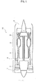
- Fig. 1 is a configuration diagram of an engine (the turbofan engine, the jet engine) 10 in which a fan 2 and an axial flow compressor 3 of the present embodiment are mounted.
- the engine 10 includes the fan 2, the compressor 3, a combustion chamber 4, and a turbine 5. These are arrayed on the axis 1 directing from the upstream side toward the downstream side of the main stream.
- the engine 10 further includes a casing (an external casing, a fan case) 7 and a casing (an internal casing, a core cowl) 8 that is housed in the casing 7 and is located coaxially with the casing 7. Both of the casing 7 and the casing 8 are formed into tubular shapes that extend along the axis 1.
- the casing 7 houses the fan 2 on inner front of the casing 7.
- the casing 8 is installed in the rear of the fan 2 in the casing 7 and houses the compressor 3, the combustion chamber 4 and the turbine 5.
- the basic operation of each unit is the same as that of the conventional one. That is, the fan 2 rotates with the axis 1 being set as the central axis, sucks gas on the front and discharges it to the rear.
- the compressor 3 compresses gas that has flown into the casing 8 in the gas (a working fluid, air in the present embodiment) that the fan 2 has sucked while decelerating it and supplies it to the combustion chamber 4.
- the combustion chamber 4 burns a mixed gas of the compressed gas with a fuel.
- the turbine 5 converts pressure energy of the burned gas that expands into rotational energy, drives the fan 2 and the compressor 3 and discharges the burned gas through an exhaust duct 6.
- the compressor 3 of a multiaxial system in which the compressor has been divided into a plurality of compressors in accordance with a pressure of the gas to be compressed may be adopted.
- the casing 8 is configured by coupling together a plurality of tubular members that houses respective units such as the compressors 3.
- the fan 2 and the compressor 3 of the present embodiment will be described. Configurations of the fan 2 and the compressor 3 will be shown by use of Fig. 2 and Fig. 3 for the convenience of description. Incidentally, sizes, shapes and so forth of the rotor blade, the stator vane and the work region expansion unit (described later) of the fan 2 and the compressor 3 are not limited to those in these drawings and can be appropriately changed as long as the advantageous effect of the present invention can be obtained. However, the scope of the present invention is solely defined by the appended claims. As shown in Fig.
- the fan 2 and the compressor 3 each include at least one stage of a compressor 30 which includes a rotor blade row (blade row) 31 that rotates centering on the axis 1 and a stator vane row (vane row) 32 that is installed in the rear of the rotor blade row 31 along the axis 1.
- the rotor blade row 31 includes a plurality of rotor blades (blades) 33 that is radially installed centering on the axis 1 (see Fig. 2(b) ).
- the rotor blade 33 of the rotor blade row 31 has a leading edge 33a that is located on the upstream side of the main stream S, and a trailing edge 33b that is located on the downstream side of the main stream S (see Fig.
- stator vanes 34 of the stator vane row 32 have the same shape. That is, also the stator vane row 32 includes a plurality of the stator vanes (vanes) 34 that is installed radially centering on the axis 1.
- the stator vane 34 is fixed to, for example, the inner surface 7a (8a) of the casing 7 (8).
- the number of stages of the compressors 30 is appropriately set in accordance with the specification of the engine 10.
- Fig. 2(a) and Fig. 2(b) show an operating range expansion unit 40 as casing treatment relating to the present embodiment.
- Fig. 2(b) is a sectional diagram along the IIB-IIB line in Fig. 2(a) .
- the axial flow device that serves as the fan 2 or the compressor 3 includes the operating range expansion unit 40. That is, the operating range expansion unit 40 is formed in at least one of the casing 7 and the casing 8, sucks part of the gas that has flown into the rotor blade row 31 through a suction port 41 and blows it out through a blow-out port 42 on the front side of the rotor blade row 31.
- the operating range expansion unit 40 is provided for the rotor blade row 31 in at least one stage of the compressor 30 in the plurality of stages of the compressors 30.
- the operating range expansion unit 40 may be provided only for the rotor blade row 31 in the first stage of the compressor 30 and may be provided for the respective rotor blade rows 31 of other stages in the compressors 30.
- the operating range expansion unit 40 has the suction port 41 and the blow-out port 42 that open in the inner surface 7a (8a) of the casing 7 (8), and a hollow section 43 that communicates the suction port 41 with the blow-out port 42.
- the suction port 41 opens into a region 7b (8b) corresponding to the rotor blade row 31 in the inner surface 7a (8a) of the casing 7 (8) and sucks part of the gas that has flown into the rotor blade row 31.
- the suction port 41 is provided posterior to a later described crossing position P.
- the region 7b (8b) is a belt-shaped part that has a width ranging from the leading edge 33a to the trailing edge 33b of the rotor blade 33 in an axial direction and extends in the circumferential direction on the inner surface 7a (8a) of the casing 7 (8).
- the region 7b (8b) is the part that corresponds to (faces) the locus of the tip 33c of the rotor blade 33 that rotates on the inner surface 7a (8a) of the casing 7 (8).
- the suction port 41 is formed into a groove shape that extends in the circumferential direction in the same sectional shape.
- a depth direction of the suction port 41 is parallel with the radial direction.
- the suction port 41 functions as a so-called diffusor that decelerates the gas that has flown in from the casing 7 and compresses it.
- a width of the suction port 41 in the axial direction is constant at any place in the radial direction. Note that a height of the hollow section 43 in the radial direction is larger than the width of the suction port 41 in a section including the axis 1. Accordingly, from the viewpoint of reducing a pressure loss, the width of the suction port 41 may be gradually widened as it goes outward in the radial direction.
- the blow-out port 42 opens anterior to the rotor blade row 31 in the inner surface 7a of the casing 7 and blows out the gas that has been sucked in through the suction port 41.
- the blow-out port 42 is formed as a groove that extends in the circumferential direction in the same sectional shape and a later described fin 44 is further provided within it.
- the blow-out port 42 extends in the radial direction in the section including the axis 1.
- a width of the blow-out port 42 in the axial direction is constant at any place in the radial direction. Incidentally, this width is smaller than the height of the hollow section 43. Accordingly, the blow-out port 42 reduces the pressure of the gas and accelerates the gas concerned when blowing it out.
- each fin 44 is formed into a plate shape that extends in the axial direction and constitutes at least a flow path of the blow-out port 42. In addition and outside the scope of the present invention, as shown in these drawings, it may project to the hollow section 43 and further may extend to the rear in the hollow section 43.
- Each fin 44 is inclined in the same direction as a rotation direction R of the rotor blade row 31 relative to the radially outward side and defines a flowing direction of the gas that is blown out through the blow-out port 42.
- the flow path (a depth direction of the blow-out port 42) in the blow-out port 42 is inclined reversely to the rotation direction R relative to the radially inward side so as to generate the gas that swirls reversely to the rotation direction R of the rotor blade row 31.
- the hollow section 43 is formed inside the casing 7 and communicates the suction port 41 with the blow-out port 42.
- the hollow section is a belt-shaped space that extends in the axial direction and extends in the circumferential direction in the same sectional shape.
- the height of the hollow section 43 in the radial direction is larger than the width of the suction port 41. Accordingly, the gas that has flown into it through the suction port 41 is decelerated and compressed and moves in the hollow section 43 toward the blow-out port 42.
- the height of the hollow section 43 in the radial direction is constant at any place in the axial direction.
- the pressure is increased toward the downstream side in the rotor blade row 31.
- a pressure difference is generated between the suction port 41 and the blow-out port 42 in response to this pressure increase.
- part of the gas in the rotor blade row 31 is sucked into the suction port 41 and blows out through the blow-out port 42.
- the operating range expansion unit 40 makes part of the gas that has flown into the rotor blade row 31 circulate between the rotor blade row 31 and the front side thereof.
- the gas that has blown out through the blow-out port 42 compensates for the flow rate of the gas that flows into the rotor blade row 31.
- the pressure difference across the rotor blade row 31 is proportional to a workload that the rotor blade row 31 has done on the gas.
- This workload is proportional to a product of a difference between circumferential-direction components of respective relative velocities of the gas (the main stream) that flows into the rotor blade row 31 and the gas (the main stream) that is discharged from the rotor blade row 31, and a rotating speed of the rotor blade row 31.
- the flow path in the blow-out port 42 is inclined reversely to the rotation direction R of the rotor blade row 31 relative to the radially inward side. Accordingly, the gas is blown out through the blow-out port 42 such that it swirls reversely to the rotation direction R.
- the flow path in the blow-out port 42 may be inclined relative to the radial direction such that it runs from the front side of the hollow section 43 toward the rotor blade row 31 in the section including the axis 1.
- the length of the flow path in the blow-out port 42 is not changed.
- the same advantageous effect as that in a case where the flow path in the blow-out port 42 extends in the radial direction in the section including the axis 1 can be obtained and it becomes possible to make the position of the hollow section 43 closer to the axis 1. Accordingly, for example, reductions in thickness and weight of the casing 7 (8) become possible.
- Fig. 4 is a graph showing a relation between a flow rate (a corrected flow rate) and a total pressure ratio by a CFD analysis.
- a circle (o) shows a result of analysis of the compressor relating to the present embodiment
- a triangle ( ⁇ ) shows a result of analysis of a compressor as a comparative example.
- the operating range expansion unit in the compressor relating to the present embodiment is omitted.
- x in the drawing is a stall point. As shown in this drawing, in the compressor relating to the present embodiment, improvement of the stall margin of 23% on the low flow rate side and 27% on the high flow rate side is observed.
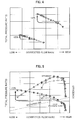
- Fig. 5 is a graph showing a relation between the flow rate (the corrected flow rate) and the total pressure ratio and a relation between the flow rate (the corrected flow rate) and efficiency by the CFD analysis.
- the circle (o) shows a result of analysis of the compressor relating to the present embodiment
- the triangle ( ⁇ ) shows a result of analysis of a compressor as a comparative example 1.
- the operating range expansion unit in the compressor relating to the present embodiment is omitted.
- a square ( ⁇ ) shows a result of analysis of a compressor as a comparative example 2.
- the flow path in the blow-out port in the operating range expansion unit of the present embodiment is inclined so as to generate the gas which swirls in the same direction as the rotation direction of the rotor blade row.
- the stall margin of the compressor of the present embodiment is drastically improved relative to those of the comparative example 1 and the comparative example 2. It is improved relative to the comparative example 1 also in terms of the efficiency and this is equal to the efficiency of the comparative example 2. That is, the efficiency is not lowered even when the casing treatment is performed.
- the fan or the axial flow compressor on which the casing treatment that suppresses a reduction in efficiency and can improve the stall margin has been performed.
Description
- The present invention relates to an axial flow device which is used as a fan or an axial flow compressor and on which casing treatment has been performed and to a jet engine.
- The axial flow device is generally known as a device that is used as the fan or the axial flow compressor and constitutes part of a turbine engine such as the jet engine. The axial flow device includes at least one stage of a compressor that has a rotor blade row including a plurality of rotor blades and rotating centering on a central axis, and a stator vane row provided in the rear of the rotor blade row and including a plurality of stator vanes. The fan is provided at the forefront of the engine and sucks the outside air. The axial flow compressor is installed between the fan and a combustion chamber, compresses gas that has been taken in from the fan while decelerating it and thereafter supplies it into the combustion chamber.
- In a case where the fan and the axial flow compressor are of a multistage system that the rotor blade row and the stator vane row are alternately arrayed, a speed, a pressure and a temperature of the gas change every time it passes through each stage. On the other hand, in a steady operation, each rotor blade row rotates with a predetermined number of rotations. Accordingly, in a relation between a flow rate and a pressure ratio of the gas, a range (a so-called operating range) that all stages work efficiently is narrow. In a case where operating states of the fan and the axial flow compressor have deviated from this operating range, a surge (a stall) is prone to occur.
- It is conceived to expand a margin (in the following, a surge margin) from a design point to a stall point in order to prevent this stall from occurring.
Patent Literatures 1 to 4 propose, as a technology of promoting expansion of this surge margin, so-called casing treatment that forms a groove or a flow path in an inner surface of a casing that houses the rotor blade row and the stator vane row. - Further, a cast casing treatment for compressor blades is known from Patent Literature 5, wherein each segment of a segmented annular shroud comprises first, second and third arcuate members and a plurality of vane walls integral with the first second and third members, and each arcuate member has a radially inner surface, and the third arcuate member is in spaced relation to the first and second members, and each vane wall spans between the radially inner surface of the third arcuate member and the radially inner surfaces of the first and second members.
- Moreover, a housing for axial flow fans is known from
Patent Literature 6, wherein the housing is a cylindrical housing for an axial-flow fan, formed with an annular recess to provide an alternative path for air flow in the reverse direction when it occurs near the outer diameter of the fan blading. The recess contains vanes whose curvature about the housing axes changes progressively from the inlet end of the recess to the outlet end and which at least at the inlet end have a curvature about an axis generally parallel to the housing axis, so that air which is travelling generally circumferentially as it enters the recess is initially deflected towards a radially-outward direction by encounter with the vanes. The recess may also contain a ring-shaped fairing which physically separates the recess inlet from its outlet and which may serve to diminish turbulence in the air travelling through the recess. - Additionally, a fan and a casing of a compressor are known from
Patent Literature 7, wherein in the case that a moving blade is rotationally moved and relative flow near the moving blade shows supersonic speed, air between the adjacent moving blades is compressed due to generation of shock wave and reduction of flow velocity. Air is compressed also by the rotation of the moving blades . A part of high pressure flow in a boundary layer behind the shock wave is supplied to an inner surface of a casing at a front position of the shock wave. At a position near the leading end of the moving blade where the peripheral speed shows a maximum value, a part of air flow passing a circulation passage is added to its back surface. - Further, an axial-flow fan is known from
Patent Literature 8 and a turbomachine exerting dynamic influence on the flow is known from Patent Literature 9. -
- Patent Literature 1:
JP 2009-236069 A - Patent Literature 2:
US 7 811 049 A - Patent Literature 3:
US 5 607 284 A - Patent Literature 4:
US 8 066 471 A - Patent Literature 5:
US 5 474 417 A - Patent Literature 6:
WO 95/18922 A1 - Patent Literature 7:
JP H08 159097 A - Patent Literature 8:
US 4 871 294 A - Patent Literature 9:
US 2006/153673 A1 - As indicated in
Patent Literatures 1 to 4, it is possible to expand the surge margin by performing the casing treatment on the inner surface of the casing. Expansion of the surge margin is always demanded with development of the turbine engine. On the other hand, as described also inPatent Literature 1, although conventional casing treatment expands the surge margin, there was a problem that it reduces efficiency inversely. - The present invention has been made in view of such circumstances. That is, the present invention aims to provide an axial flow device on which the casing treatment that suppresses a reduction in efficiency and can improve the stall margin has been performed, and a jet engine.
- According to a first aspect of the present invention, there is provided an axial flow device that is used as a fan or an axial flow compressor, comprising: at least one stage of a compressor including a rotor blade row and a stator vane row; a tubular casing housing the compressor; and an operating range expansion unit having a suction port that opens in an inner surface of the casing, a blow-out port that opens anterior to the rotor blade row in the inner surface of the casing, and a hollow section that is formed inside the casing and communicates the suction port with the blow-out port, wherein a flow path in the blow-out port is inclined reversely to a rotation direction of the rotor blade row relative to the radially inward side, wherein the suction port opens into a region in the inner surface of the casing, the region facing and corresponding to a locus of a tip of a rotor blade of the rotor blade row in a radial direction when the rotor blade row rotates, the suction port is formed into a groove shape that annularly extends in a circumferential direction in the same sectional shape, the hollow section is a belt-shaped space that extends in the circumferential direction in a same sectional shape, and a plurality of fins that is installed at intervals in a circumferential direction in the blow-out port and constitutes the flow path of the blow-out port.
- According to this configuration, a height of the hollow section in a radial direction may be larger than a width of the suction port in an axial direction.
- The flow path of the blow-out port may run from the hollow section toward the rotor blade row with an inclination relative to the radial direction in a section including a central axis of the tubular casing.
- The compressor may be provided in a plurality of stages and the operating range expansion unit may be provided for the rotor blade row in at least one stage of the compressor in the plurality of stages of the compressors.
- In addition, a second aspect of the present invention is a jet engine that includes the axial flow device relating to the first aspect.
- According to the present invention, there can be provided the axial flow device on which the casing treatment that suppresses the reduction in efficiency and can improve the stall margin has been performed.
-
- [
Fig. 1] Fig. 1 is a configuration diagram of a turbofan engine in which a fan and an axial flow compressor of the present embodiment are mounted. - [
Fig. 2] Fig. 2 (a) and Fig. 2 (b) are diagrams for explaining an operating range expansion unit relating to the present embodiment, in whichFig. 2(b) is a sectional diagram along a IIB-IIB line inFig. 2(a) . - [
Fig. 3] Fig. 3 is a diagram for explaining a modified example of the operating range expansion unit relating to the present embodiment. - [
Fig. 4] Fig. 4 is a graph showing a relation between a flow rate (a corrected flow rate) and a total pressure ratio by a CFD (Computational Fluid Dynamics) analysis. - [
Fig. 5] Fig. 5 is a graph showing a relation between the flow rate (the corrected flow rate) and the total pressure ratio and a relation between the flow rate (the corrected flow rate) and efficiency by the CFD analysis. - In the following, an axial flow device relating to an embodiment of the present invention will be described on the basis of the appended drawings. Incidentally, in the respective drawings, the same numerals are assigned to common parts and duplicated description is omitted. In the respective drawings, the left side (the left) is defined as the front side (the front) or the upstream side of a main stream S (see
Fig. 2(a) ) and the right side (the right) is defined as the rear side (the rear) or the downstream side of the main stream S. In addition, inFig. 1 , anaxis 1 is shown as a central axis and an extending direction thereof is referred to as an axial direction. Further, a circumferential direction and a radial direction are defined with theaxis 1 being set as a reference. - The axial flow device of the present embodiment is used as a fan and an axial flow compressor and constitutes part of a turbofan engine that is one of gas turbine engines. However, the engine that includes the axial flow device of the present embodiment is not limited to the turbofan engine and is also applicable to jet engines such as a turbojet engine, a turboprop engine, a turboshaft engine, and a turbo-ram jet engine. In addition, also application of the gas turbine engine is not limited to use for air crafts. It is also applicable to, for example, gas turbine engines for ships and for power generation. In the following, the axial flow compressor will be simply referred to as a compressor and the turbofan engine will be simply referred to as an engine for the convenience of description.
-
Fig. 1 is a configuration diagram of an engine (the turbofan engine, the jet engine) 10 in which afan 2 and anaxial flow compressor 3 of the present embodiment are mounted. As shown in this drawing, theengine 10 includes thefan 2, thecompressor 3, a combustion chamber 4, and a turbine 5. These are arrayed on theaxis 1 directing from the upstream side toward the downstream side of the main stream. Theengine 10 further includes a casing (an external casing, a fan case) 7 and a casing (an internal casing, a core cowl) 8 that is housed in thecasing 7 and is located coaxially with thecasing 7. Both of thecasing 7 and thecasing 8 are formed into tubular shapes that extend along theaxis 1. Thecasing 7 houses thefan 2 on inner front of thecasing 7. Thecasing 8 is installed in the rear of thefan 2 in thecasing 7 and houses thecompressor 3, the combustion chamber 4 and the turbine 5. The basic operation of each unit is the same as that of the conventional one. That is, thefan 2 rotates with theaxis 1 being set as the central axis, sucks gas on the front and discharges it to the rear. Thecompressor 3 compresses gas that has flown into thecasing 8 in the gas (a working fluid, air in the present embodiment) that thefan 2 has sucked while decelerating it and supplies it to the combustion chamber 4. The combustion chamber 4 burns a mixed gas of the compressed gas with a fuel. The turbine 5 converts pressure energy of the burned gas that expands into rotational energy, drives thefan 2 and thecompressor 3 and discharges the burned gas through anexhaust duct 6. Incidentally, thecompressor 3 of a multiaxial system in which the compressor has been divided into a plurality of compressors in accordance with a pressure of the gas to be compressed may be adopted. The same applies to the turbine 5. In addition, thecasing 8 is configured by coupling together a plurality of tubular members that houses respective units such as thecompressors 3. - The
fan 2 and thecompressor 3 of the present embodiment will be described. Configurations of thefan 2 and thecompressor 3 will be shown by use ofFig. 2 andFig. 3 for the convenience of description. Incidentally, sizes, shapes and so forth of the rotor blade, the stator vane and the work region expansion unit (described later) of thefan 2 and thecompressor 3 are not limited to those in these drawings and can be appropriately changed as long as the advantageous effect of the present invention can be obtained. However, the scope of the present invention is solely defined by the appended claims. As shown inFig. 2 , thefan 2 and thecompressor 3 each include at least one stage of acompressor 30 which includes a rotor blade row (blade row) 31 that rotates centering on theaxis 1 and a stator vane row (vane row) 32 that is installed in the rear of therotor blade row 31 along theaxis 1. Therotor blade row 31 includes a plurality of rotor blades (blades) 33 that is radially installed centering on the axis 1 (seeFig. 2(b) ). Therotor blade 33 of therotor blade row 31 has aleading edge 33a that is located on the upstream side of the main stream S, and a trailingedge 33b that is located on the downstream side of the main stream S (seeFig. 2(a) ). In addition, atip 33c of therotor blade 33 is slightly separated from an inner surface 7a (8a) of the casing 7 (8). All of therotor blades 33 have the same sectional shape and are curved so as to project in the same direction in the circumferential direction. Incidentally, alsostator vanes 34 of thestator vane row 32 have the same shape. That is, also thestator vane row 32 includes a plurality of the stator vanes (vanes) 34 that is installed radially centering on theaxis 1. Thestator vane 34 is fixed to, for example, the inner surface 7a (8a) of the casing 7 (8). Incidentally, the number of stages of thecompressors 30 is appropriately set in accordance with the specification of theengine 10. -
Fig. 2(a) and Fig. 2(b) show an operatingrange expansion unit 40 as casing treatment relating to the present embodiment.Fig. 2(b) is a sectional diagram along the IIB-IIB line inFig. 2(a) . As shown inFig. 2(a) , the axial flow device that serves as thefan 2 or thecompressor 3 includes the operatingrange expansion unit 40. That is, the operatingrange expansion unit 40 is formed in at least one of thecasing 7 and thecasing 8, sucks part of the gas that has flown into therotor blade row 31 through asuction port 41 and blows it out through a blow-outport 42 on the front side of therotor blade row 31. In a case where the axial flow device of the present embodiment has a plurality of stages of thecompressors 30, the operatingrange expansion unit 40 is provided for therotor blade row 31 in at least one stage of thecompressor 30 in the plurality of stages of thecompressors 30. For example, the operatingrange expansion unit 40 may be provided only for therotor blade row 31 in the first stage of thecompressor 30 and may be provided for the respectiverotor blade rows 31 of other stages in thecompressors 30. - The operating
range expansion unit 40 has thesuction port 41 and the blow-outport 42 that open in the inner surface 7a (8a) of the casing 7 (8), and ahollow section 43 that communicates thesuction port 41 with the blow-outport 42. Thesuction port 41 opens into aregion 7b (8b) corresponding to therotor blade row 31 in the inner surface 7a (8a) of the casing 7 (8) and sucks part of the gas that has flown into therotor blade row 31. In addition, thesuction port 41 is provided posterior to a later described crossing position P. Theregion 7b (8b) is a belt-shaped part that has a width ranging from theleading edge 33a to the trailingedge 33b of therotor blade 33 in an axial direction and extends in the circumferential direction on the inner surface 7a (8a) of the casing 7 (8). In other words, theregion 7b (8b) is the part that corresponds to (faces) the locus of thetip 33c of therotor blade 33 that rotates on the inner surface 7a (8a) of the casing 7 (8). - In the following, an example in which the operating
range expansion unit 40 is formed in thecasing 7 will be described. Since the configuration of the operatingrange expansion unit 40 is the same also in a case where it is formed in thecasing 8, detailed description thereof is omitted unless otherwise noted in particular. - The
suction port 41 is formed into a groove shape that extends in the circumferential direction in the same sectional shape. A depth direction of thesuction port 41 is parallel with the radial direction. Thesuction port 41 functions as a so-called diffusor that decelerates the gas that has flown in from thecasing 7 and compresses it. A width of thesuction port 41 in the axial direction is constant at any place in the radial direction. Note that a height of thehollow section 43 in the radial direction is larger than the width of thesuction port 41 in a section including theaxis 1. Accordingly, from the viewpoint of reducing a pressure loss, the width of thesuction port 41 may be gradually widened as it goes outward in the radial direction. - The blow-out
port 42 opens anterior to therotor blade row 31 in the inner surface 7a of thecasing 7 and blows out the gas that has been sucked in through thesuction port 41. The blow-outport 42 is formed as a groove that extends in the circumferential direction in the same sectional shape and a later describedfin 44 is further provided within it. The blow-outport 42 extends in the radial direction in the section including theaxis 1. In addition, a width of the blow-outport 42 in the axial direction is constant at any place in the radial direction. Incidentally, this width is smaller than the height of thehollow section 43. Accordingly, the blow-outport 42 reduces the pressure of the gas and accelerates the gas concerned when blowing it out. - As shown in
Fig. 2 (a) and Fig. 2(b) , a plurality of thefins 44 that has been installed at intervals in the circumferential direction is provided in the blow-outport 42. Eachfin 44 is formed into a plate shape that extends in the axial direction and constitutes at least a flow path of the blow-outport 42. In addition and outside the scope of the present invention, as shown in these drawings, it may project to thehollow section 43 and further may extend to the rear in thehollow section 43. Eachfin 44 is inclined in the same direction as a rotation direction R of therotor blade row 31 relative to the radially outward side and defines a flowing direction of the gas that is blown out through the blow-outport 42. In other words, the flow path (a depth direction of the blow-out port 42) in the blow-outport 42 is inclined reversely to the rotation direction R relative to the radially inward side so as to generate the gas that swirls reversely to the rotation direction R of therotor blade row 31. - The
hollow section 43 is formed inside thecasing 7 and communicates thesuction port 41 with the blow-outport 42. The hollow section is a belt-shaped space that extends in the axial direction and extends in the circumferential direction in the same sectional shape. As described above, the height of thehollow section 43 in the radial direction is larger than the width of thesuction port 41. Accordingly, the gas that has flown into it through thesuction port 41 is decelerated and compressed and moves in thehollow section 43 toward the blow-outport 42. The height of thehollow section 43 in the radial direction is constant at any place in the axial direction. - An operation and advantageous effects of the operating
range expansion unit 40 owing to the above-mentioned configuration will be described. The pressure is increased toward the downstream side in therotor blade row 31. A pressure difference is generated between thesuction port 41 and the blow-outport 42 in response to this pressure increase. As a result, part of the gas in therotor blade row 31 is sucked into thesuction port 41 and blows out through the blow-outport 42. In other words, the operatingrange expansion unit 40 makes part of the gas that has flown into therotor blade row 31 circulate between therotor blade row 31 and the front side thereof. The gas that has blown out through the blow-outport 42 compensates for the flow rate of the gas that flows into therotor blade row 31. Accordingly, at a flow rate that a surge occurs in a general compressor in which the operatingrange expansion unit 40 is not provided, occurrence of the surge concerned can be prevented. That is, it becomes possible to move a stall point of thefan 2 or thecompressor 3 closer to the low flow rate side. That is, a stall margin is improved. - In addition the pressure difference across the
rotor blade row 31 is proportional to a workload that therotor blade row 31 has done on the gas. This workload is proportional to a product of a difference between circumferential-direction components of respective relative velocities of the gas (the main stream) that flows into therotor blade row 31 and the gas (the main stream) that is discharged from therotor blade row 31, and a rotating speed of therotor blade row 31. In the present embodiment, the flow path in the blow-outport 42 is inclined reversely to the rotation direction R of therotor blade row 31 relative to the radially inward side. Accordingly, the gas is blown out through the blow-outport 42 such that it swirls reversely to the rotation direction R. The difference in the above-mentioned relative velocity becomes large by blowing-out of the gas that generates this reverse swirling flow and, as a result, the workload is increased. However, since an incidence angle that is a difference between an inflow angle of a flow into therotor blade row 31 and a blade inlet angle of therotor blade 33 becomes large in comparison with a case where the operatingrange expansion unit 40 is not provided, separation on the back side of therotor blade 33 is increased. Accordingly, it is possible to avoid the surge concerned and increase the surge margin by sucking out a separation region on the back side of the aforementioned rotor blade by thesuction port 41. - Incidentally, in a case where the
rotor blade row 31 rotates at a high speed, part of the main stream S reaches an acoustic velocity between therotor blades 33 and, as a result, a shock wave is generated. This shock wave arrives at the inner surface 7a (theregion 7b) of the casing 7 (the inner surface 8a (theregion 8b) of the casing 8). When therotor blade row 31 rotates at a design point, this arrival point is located at a crossing position P shown inFig. 2(a) . In addition, since when the flow rate is reduced, this arrival point moves forward from the crossing position P and the pressure in thesuction port 41 is increased, the pressure difference between thesuction port 41 and the blow-outport 42 is increased and the flow rate that it is sucked in through thesuction port 41 is increased. Accordingly, in a case where thesuction port 41 is provided posterior to the crossing position P, it becomes possible to increase an inflow amount thereof into thesuction port 41 and a blow-out amount thereof through the blow-outport 42 when the flow rate is reduced. On the other hand, since, at the design point, the pressure difference between thesuction port 41 and the blow-outport 42 is small and the inflow amount thereof into thesuction port 41 and the blow-out amount thereof through the blow-outport 42 are little, it does not worsen the efficiency. - In addition, as shown in
Fig. 3 , the flow path in the blow-outport 42 may be inclined relative to the radial direction such that it runs from the front side of thehollow section 43 toward therotor blade row 31 in the section including theaxis 1. However, the length of the flow path in the blow-outport 42 is not changed. In this case, the same advantageous effect as that in a case where the flow path in the blow-outport 42 extends in the radial direction in the section including theaxis 1 can be obtained and it becomes possible to make the position of thehollow section 43 closer to theaxis 1. Accordingly, for example, reductions in thickness and weight of the casing 7 (8) become possible. -
Fig. 4 is a graph showing a relation between a flow rate (a corrected flow rate) and a total pressure ratio by a CFD analysis. A circle (o) shows a result of analysis of the compressor relating to the present embodiment, and a triangle (Δ) shows a result of analysis of a compressor as a comparative example. In the compressor of the comparative example, the operating range expansion unit in the compressor relating to the present embodiment is omitted. In addition, x in the drawing is a stall point. As shown in this drawing, in the compressor relating to the present embodiment, improvement of the stall margin of 23% on the low flow rate side and 27% on the high flow rate side is observed. -
Fig. 5 is a graph showing a relation between the flow rate (the corrected flow rate) and the total pressure ratio and a relation between the flow rate (the corrected flow rate) and efficiency by the CFD analysis. The circle (o) shows a result of analysis of the compressor relating to the present embodiment, and the triangle (Δ) shows a result of analysis of a compressor as a comparative example 1. In the compressor of the comparative example 1, the operating range expansion unit in the compressor relating to the present embodiment is omitted. Further, a square (□) shows a result of analysis of a compressor as a comparative example 2. In the compressor of the comparative example 2, the flow path in the blow-out port in the operating range expansion unit of the present embodiment is inclined so as to generate the gas which swirls in the same direction as the rotation direction of the rotor blade row. As shown inFig. 5 , the stall margin of the compressor of the present embodiment is drastically improved relative to those of the comparative example 1 and the comparative example 2. It is improved relative to the comparative example 1 also in terms of the efficiency and this is equal to the efficiency of the comparative example 2. That is, the efficiency is not lowered even when the casing treatment is performed. - As mentioned above, according to the present invention, there is provided the fan or the axial flow compressor on which the casing treatment that suppresses a reduction in efficiency and can improve the stall margin has been performed.
Claims (5)
- An axial flow device that is used as a fan (2) or an axial flow compressor (3), comprising:at least one stage of a compressor (30) including a rotor blade row (31) and a stator vane row (32);a tubular casing (7) housing the compressor (30); andan operating range expansion unit (40) having a suction port (41) that opens in an inner surface (7a) of the casing (7), a blow-out port (42) that opens anterior to the rotor blade row (31) in the inner surface (7a) of the casing (7), and a hollow section (43) that is formed inside the casing (7) and communicates the suction port (41) with the blow-out port (42), whereina flow path in the blow-out port (42) is inclined reversely to a rotation direction of the rotor blade row (31) relative to the radially inward side,the suction port (41) is formed into a groove shape that annularly extends in a circumferential direction in the same sectional shape,the hollow section (43) is a belt-shaped space that extends in the circumferential direction in a same sectional shape, anda plurality of fins (44) is installed at intervals in a circumferential direction in the blow-out port (42) and constitutes the flow path of the blow-out port (42), and characterized in that
the suction port (41) opens into a region (7b) in the inner surface (7a) of the casing (7), the region facing and corresponding to a locus of a tip of a rotor blade of the rotor blade row (31) in a radial direction when the rotor blade row rotates. - The axial flow device according to claim 1, wherein
a height of the hollow section (43) in the radial direction is larger than a width of the suction port (41) in an axial direction. - The axial flow device according to claim 1 or 2, wherein
the flow path of the blow-out port (42) runs from a front side of the hollow section (43) toward the rotor blade row (31) with an inclination relative to the radial direction in a section including a central axis of the tubular casing (7). - The axial flow device according to any one of claims 1 to 3, wherein
the compressor (30) is provided in a plurality of stages and the operating range expansion unit (40) is provided for the rotor blade row (31) in the at least one stage of the compressor (30) in the plurality of stages of the compressors (30). - A jet engine (10), comprising an axial flow device according to any one of claims 1 to 4.
Applications Claiming Priority (2)
| Application Number | Priority Date | Filing Date | Title |
|---|---|---|---|
| JP2014258675A JP2016118165A (en) | 2014-12-22 | 2014-12-22 | Axial flow machine and jet engine |
| PCT/JP2015/075677 WO2016103799A1 (en) | 2014-12-22 | 2015-09-10 | Axial flow device and jet engine |
Publications (3)
| Publication Number | Publication Date |
|---|---|
| EP3176442A1 EP3176442A1 (en) | 2017-06-07 |
| EP3176442A4 EP3176442A4 (en) | 2018-03-21 |
| EP3176442B1 true EP3176442B1 (en) | 2020-11-11 |
Family
ID=56149840
Family Applications (1)
| Application Number | Title | Priority Date | Filing Date |
|---|---|---|---|
| EP15872368.4A Active EP3176442B1 (en) | 2014-12-22 | 2015-09-10 | Axial flow device with casing treatment and jet engine |
Country Status (4)
| Country | Link |
|---|---|
| US (1) | US20170175676A1 (en) |
| EP (1) | EP3176442B1 (en) |
| JP (1) | JP2016118165A (en) |
| WO (1) | WO2016103799A1 (en) |
Families Citing this family (8)
| Publication number | Priority date | Publication date | Assignee | Title |
|---|---|---|---|---|
| CN107152419B (en) * | 2017-07-24 | 2019-07-02 | 北京航空航天大学 | A kind of big bending angle compressor stator blade of root series connection multistage blade profile |
| CA3096715A1 (en) * | 2018-04-24 | 2019-10-31 | Wallace PITTS | Magnetically programmable actuators for tactile conveyance of information |
| JP7221078B2 (en) | 2019-02-27 | 2023-02-13 | 三菱重工業株式会社 | Wings and rotating machines equipped with them [2006.01] |
| JP7400314B2 (en) | 2019-10-03 | 2023-12-19 | 株式会社Ihi | Fan or compressor airflow control device |
| JP7443087B2 (en) * | 2020-02-26 | 2024-03-05 | 本田技研工業株式会社 | axial compressor |
| US11702945B2 (en) | 2021-12-22 | 2023-07-18 | Rolls-Royce North American Technologies Inc. | Turbine engine fan case with tip injection air recirculation passage |
| US11946379B2 (en) | 2021-12-22 | 2024-04-02 | Rolls-Royce North American Technologies Inc. | Turbine engine fan case with manifolded tip injection air recirculation passages |
| US11732612B2 (en) * | 2021-12-22 | 2023-08-22 | Rolls-Royce North American Technologies Inc. | Turbine engine fan track liner with tip injection air recirculation passage |
Citations (2)
| Publication number | Priority date | Publication date | Assignee | Title |
|---|---|---|---|---|
| US4871294A (en) * | 1982-06-29 | 1989-10-03 | Ivanov Sergei K | Axial-flow fan |
| US20060153673A1 (en) * | 2004-11-17 | 2006-07-13 | Volker Guemmer | Turbomachine exerting dynamic influence on the flow |
Family Cites Families (13)
| Publication number | Priority date | Publication date | Assignee | Title |
|---|---|---|---|---|
| GB9400254D0 (en) * | 1994-01-07 | 1994-03-02 | Britisch Technology Group Limi | Improvements in or relating to housings for axial flow fans |
| JPH08159097A (en) * | 1994-12-08 | 1996-06-18 | Ishikawajima Harima Heavy Ind Co Ltd | Fan and casing of compressor |
| US5474417A (en) * | 1994-12-29 | 1995-12-12 | United Technologies Corporation | Cast casing treatment for compressor blades |
| US5607284A (en) * | 1994-12-29 | 1997-03-04 | United Technologies Corporation | Baffled passage casing treatment for compressor blades |
| JP3575164B2 (en) * | 1995-05-09 | 2004-10-13 | 株式会社日立製作所 | Axial fan and air separator used for it |
| WO2004018844A1 (en) * | 2002-08-23 | 2004-03-04 | Mtu Aero Engines Gmbh | Recirculation structure for a turbocompressor |
| US7631483B2 (en) * | 2003-09-22 | 2009-12-15 | General Electric Company | Method and system for reduction of jet engine noise |
| EP1862641A1 (en) * | 2006-06-02 | 2007-12-05 | Siemens Aktiengesellschaft | Annular flow channel for axial flow turbomachine |
| DE102007037924A1 (en) * | 2007-08-10 | 2009-02-12 | Rolls-Royce Deutschland Ltd & Co Kg | Turbomachine with Ringkanalwandausnehmung |
| FR2940374B1 (en) * | 2008-12-23 | 2015-02-20 | Snecma | COMPRESSOR HOUSING WITH OPTIMIZED CAVITIES. |
| JP5479021B2 (en) * | 2009-10-16 | 2014-04-23 | 三菱重工業株式会社 | Exhaust turbocharger compressor |
| US9115594B2 (en) * | 2010-12-28 | 2015-08-25 | Rolls-Royce Corporation | Compressor casing treatment for gas turbine engine |
| JP2013040587A (en) * | 2011-08-18 | 2013-02-28 | Ihi Corp | Centrifugal compressor |
-
2014
- 2014-12-22 JP JP2014258675A patent/JP2016118165A/en active Pending
-
2015
- 2015-09-10 EP EP15872368.4A patent/EP3176442B1/en active Active
- 2015-09-10 WO PCT/JP2015/075677 patent/WO2016103799A1/en active Application Filing
-
2017
- 2017-03-07 US US15/452,228 patent/US20170175676A1/en not_active Abandoned
Patent Citations (2)
| Publication number | Priority date | Publication date | Assignee | Title |
|---|---|---|---|---|
| US4871294A (en) * | 1982-06-29 | 1989-10-03 | Ivanov Sergei K | Axial-flow fan |
| US20060153673A1 (en) * | 2004-11-17 | 2006-07-13 | Volker Guemmer | Turbomachine exerting dynamic influence on the flow |
Also Published As
| Publication number | Publication date |
|---|---|
| US20170175676A1 (en) | 2017-06-22 |
| EP3176442A1 (en) | 2017-06-07 |
| JP2016118165A (en) | 2016-06-30 |
| EP3176442A4 (en) | 2018-03-21 |
| WO2016103799A1 (en) | 2016-06-30 |
Similar Documents
| Publication | Publication Date | Title |
|---|---|---|
| EP3176442B1 (en) | Axial flow device with casing treatment and jet engine | |
| EP2520763B1 (en) | Impeller | |
| EP2775119B1 (en) | Compressor shroud reverse bleed holes | |
| EP2662528B1 (en) | Gas turbine engine component with cooling holes having a multi-lobe configuration | |
| JPS5810600B2 (en) | Axial compressor casing | |
| EP2554793B1 (en) | Inter-turbine ducts with guide vanes of a gas turbine engine | |
| US11131205B2 (en) | Inter-turbine ducts with flow control mechanisms | |
| JP2016109124A (en) | Axial compressor endwall treatment for controlling leakage flow | |
| EP3044422B1 (en) | Can-annular gas turbine engine combustor arrangement having tangentially oriented combustor cans with radial midframe baffles | |
| US9822792B2 (en) | Assembly for a fluid flow machine | |
| JPWO2015072256A1 (en) | Axial turbomachine blade structure and gas turbine engine | |
| US10519976B2 (en) | Fluid diodes with ridges to control boundary layer in axial compressor stator vane | |
| EP3940199A1 (en) | System and method for air injection passageway integration and optimization in turbomachinery | |
| US11149555B2 (en) | Turbine engine component with deflector | |
| EP3354848B1 (en) | Inter-turbine ducts with multiple splitter blades | |
| EP3555429B1 (en) | Exhaust system for a gas turbine engine | |
| CN109083687B (en) | Method of minimizing cross flow across cooling holes and component for turbine engine | |
| CA2846376C (en) | Turbo-machinery rotors with rounded tip edge | |
| US11867090B2 (en) | Stator vane and aircraft gas turbine engine | |
| US11781504B2 (en) | Bleed plenum for compressor section | |
| CN113389599B (en) | Turbine engine with high acceleration and low blade turning airfoils | |
| US20200224549A1 (en) | Compressor for gas turbine engine with variable vaneless gap | |
| JP2023022719A (en) | Axial flow type turbo machine |
Legal Events
| Date | Code | Title | Description |
|---|---|---|---|
| STAA | Information on the status of an ep patent application or granted ep patent |
Free format text: STATUS: THE INTERNATIONAL PUBLICATION HAS BEEN MADE |
|
| 17P | Request for examination filed |
Effective date: 20170228 |
|
| AK | Designated contracting states |
Kind code of ref document: A1 Designated state(s): AL AT BE BG CH CY CZ DE DK EE ES FI FR GB GR HR HU IE IS IT LI LT LU LV MC MK MT NL NO PL PT RO RS SE SI SK SM TR |
|
| AX | Request for extension of the european patent |
Extension state: BA ME |
|
| PUAI | Public reference made under article 153(3) epc to a published international application that has entered the european phase |
Free format text: ORIGINAL CODE: 0009012 |
|
| STAA | Information on the status of an ep patent application or granted ep patent |
Free format text: STATUS: REQUEST FOR EXAMINATION WAS MADE |
|
| REG | Reference to a national code |
Ref country code: DE Ref legal event code: R079 Ref document number: 602015061998 Country of ref document: DE Free format text: PREVIOUS MAIN CLASS: F04D0029540000 Ipc: F04D0029680000 |
|
| RIC1 | Information provided on ipc code assigned before grant |
Ipc: F04D 29/68 20060101AFI20180208BHEP Ipc: F04D 29/52 20060101ALI20180208BHEP Ipc: F02C 7/04 20060101ALI20180208BHEP |
|
| A4 | Supplementary search report drawn up and despatched |
Effective date: 20180215 |
|
| DAV | Request for validation of the european patent (deleted) | ||
| DAX | Request for extension of the european patent (deleted) | ||
| STAA | Information on the status of an ep patent application or granted ep patent |
Free format text: STATUS: EXAMINATION IS IN PROGRESS |
|
| 17Q | First examination report despatched |
Effective date: 20181212 |
|
| GRAP | Despatch of communication of intention to grant a patent |
Free format text: ORIGINAL CODE: EPIDOSNIGR1 |
|
| STAA | Information on the status of an ep patent application or granted ep patent |
Free format text: STATUS: GRANT OF PATENT IS INTENDED |
|
| INTG | Intention to grant announced |
Effective date: 20200416 |
|
| GRAS | Grant fee paid |
Free format text: ORIGINAL CODE: EPIDOSNIGR3 |
|
| GRAA | (expected) grant |
Free format text: ORIGINAL CODE: 0009210 |
|
| STAA | Information on the status of an ep patent application or granted ep patent |
Free format text: STATUS: THE PATENT HAS BEEN GRANTED |
|
| AK | Designated contracting states |
Kind code of ref document: B1 Designated state(s): AL AT BE BG CH CY CZ DE DK EE ES FI FR GB GR HR HU IE IS IT LI LT LU LV MC MK MT NL NO PL PT RO RS SE SI SK SM TR |
|
| REG | Reference to a national code |
Ref country code: GB Ref legal event code: FG4D |
|
| REG | Reference to a national code |
Ref country code: CH Ref legal event code: EP |
|
| REG | Reference to a national code |
Ref country code: AT Ref legal event code: REF Ref document number: 1333741 Country of ref document: AT Kind code of ref document: T Effective date: 20201115 |
|
| REG | Reference to a national code |
Ref country code: DE Ref legal event code: R096 Ref document number: 602015061998 Country of ref document: DE |
|
| REG | Reference to a national code |
Ref country code: IE Ref legal event code: FG4D |
|
| REG | Reference to a national code |
Ref country code: NL Ref legal event code: MP Effective date: 20201111 |
|
| REG | Reference to a national code |
Ref country code: AT Ref legal event code: MK05 Ref document number: 1333741 Country of ref document: AT Kind code of ref document: T Effective date: 20201111 |
|
| PG25 | Lapsed in a contracting state [announced via postgrant information from national office to epo] |
Ref country code: GR Free format text: LAPSE BECAUSE OF FAILURE TO SUBMIT A TRANSLATION OF THE DESCRIPTION OR TO PAY THE FEE WITHIN THE PRESCRIBED TIME-LIMIT Effective date: 20210212 Ref country code: RS Free format text: LAPSE BECAUSE OF FAILURE TO SUBMIT A TRANSLATION OF THE DESCRIPTION OR TO PAY THE FEE WITHIN THE PRESCRIBED TIME-LIMIT Effective date: 20201111 Ref country code: PT Free format text: LAPSE BECAUSE OF FAILURE TO SUBMIT A TRANSLATION OF THE DESCRIPTION OR TO PAY THE FEE WITHIN THE PRESCRIBED TIME-LIMIT Effective date: 20210311 Ref country code: FI Free format text: LAPSE BECAUSE OF FAILURE TO SUBMIT A TRANSLATION OF THE DESCRIPTION OR TO PAY THE FEE WITHIN THE PRESCRIBED TIME-LIMIT Effective date: 20201111 Ref country code: NO Free format text: LAPSE BECAUSE OF FAILURE TO SUBMIT A TRANSLATION OF THE DESCRIPTION OR TO PAY THE FEE WITHIN THE PRESCRIBED TIME-LIMIT Effective date: 20210211 |
|
| PG25 | Lapsed in a contracting state [announced via postgrant information from national office to epo] |
Ref country code: BG Free format text: LAPSE BECAUSE OF FAILURE TO SUBMIT A TRANSLATION OF THE DESCRIPTION OR TO PAY THE FEE WITHIN THE PRESCRIBED TIME-LIMIT Effective date: 20210211 Ref country code: IS Free format text: LAPSE BECAUSE OF FAILURE TO SUBMIT A TRANSLATION OF THE DESCRIPTION OR TO PAY THE FEE WITHIN THE PRESCRIBED TIME-LIMIT Effective date: 20210311 Ref country code: SE Free format text: LAPSE BECAUSE OF FAILURE TO SUBMIT A TRANSLATION OF THE DESCRIPTION OR TO PAY THE FEE WITHIN THE PRESCRIBED TIME-LIMIT Effective date: 20201111 Ref country code: PL Free format text: LAPSE BECAUSE OF FAILURE TO SUBMIT A TRANSLATION OF THE DESCRIPTION OR TO PAY THE FEE WITHIN THE PRESCRIBED TIME-LIMIT Effective date: 20201111 Ref country code: LV Free format text: LAPSE BECAUSE OF FAILURE TO SUBMIT A TRANSLATION OF THE DESCRIPTION OR TO PAY THE FEE WITHIN THE PRESCRIBED TIME-LIMIT Effective date: 20201111 Ref country code: AT Free format text: LAPSE BECAUSE OF FAILURE TO SUBMIT A TRANSLATION OF THE DESCRIPTION OR TO PAY THE FEE WITHIN THE PRESCRIBED TIME-LIMIT Effective date: 20201111 |
|
| REG | Reference to a national code |
Ref country code: LT Ref legal event code: MG9D |
|
| PG25 | Lapsed in a contracting state [announced via postgrant information from national office to epo] |
Ref country code: HR Free format text: LAPSE BECAUSE OF FAILURE TO SUBMIT A TRANSLATION OF THE DESCRIPTION OR TO PAY THE FEE WITHIN THE PRESCRIBED TIME-LIMIT Effective date: 20201111 |
|
| PG25 | Lapsed in a contracting state [announced via postgrant information from national office to epo] |
Ref country code: RO Free format text: LAPSE BECAUSE OF FAILURE TO SUBMIT A TRANSLATION OF THE DESCRIPTION OR TO PAY THE FEE WITHIN THE PRESCRIBED TIME-LIMIT Effective date: 20201111 Ref country code: SK Free format text: LAPSE BECAUSE OF FAILURE TO SUBMIT A TRANSLATION OF THE DESCRIPTION OR TO PAY THE FEE WITHIN THE PRESCRIBED TIME-LIMIT Effective date: 20201111 Ref country code: CZ Free format text: LAPSE BECAUSE OF FAILURE TO SUBMIT A TRANSLATION OF THE DESCRIPTION OR TO PAY THE FEE WITHIN THE PRESCRIBED TIME-LIMIT Effective date: 20201111 Ref country code: EE Free format text: LAPSE BECAUSE OF FAILURE TO SUBMIT A TRANSLATION OF THE DESCRIPTION OR TO PAY THE FEE WITHIN THE PRESCRIBED TIME-LIMIT Effective date: 20201111 Ref country code: SM Free format text: LAPSE BECAUSE OF FAILURE TO SUBMIT A TRANSLATION OF THE DESCRIPTION OR TO PAY THE FEE WITHIN THE PRESCRIBED TIME-LIMIT Effective date: 20201111 Ref country code: LT Free format text: LAPSE BECAUSE OF FAILURE TO SUBMIT A TRANSLATION OF THE DESCRIPTION OR TO PAY THE FEE WITHIN THE PRESCRIBED TIME-LIMIT Effective date: 20201111 |
|
| REG | Reference to a national code |
Ref country code: DE Ref legal event code: R097 Ref document number: 602015061998 Country of ref document: DE |
|
| PG25 | Lapsed in a contracting state [announced via postgrant information from national office to epo] |
Ref country code: DK Free format text: LAPSE BECAUSE OF FAILURE TO SUBMIT A TRANSLATION OF THE DESCRIPTION OR TO PAY THE FEE WITHIN THE PRESCRIBED TIME-LIMIT Effective date: 20201111 |
|
| PLBE | No opposition filed within time limit |
Free format text: ORIGINAL CODE: 0009261 |
|
| STAA | Information on the status of an ep patent application or granted ep patent |
Free format text: STATUS: NO OPPOSITION FILED WITHIN TIME LIMIT |
|
| 26N | No opposition filed |
Effective date: 20210812 |
|
| PG25 | Lapsed in a contracting state [announced via postgrant information from national office to epo] |
Ref country code: NL Free format text: LAPSE BECAUSE OF FAILURE TO SUBMIT A TRANSLATION OF THE DESCRIPTION OR TO PAY THE FEE WITHIN THE PRESCRIBED TIME-LIMIT Effective date: 20201111 Ref country code: AL Free format text: LAPSE BECAUSE OF FAILURE TO SUBMIT A TRANSLATION OF THE DESCRIPTION OR TO PAY THE FEE WITHIN THE PRESCRIBED TIME-LIMIT Effective date: 20201111 Ref country code: IT Free format text: LAPSE BECAUSE OF FAILURE TO SUBMIT A TRANSLATION OF THE DESCRIPTION OR TO PAY THE FEE WITHIN THE PRESCRIBED TIME-LIMIT Effective date: 20201111 |
|
| PG25 | Lapsed in a contracting state [announced via postgrant information from national office to epo] |
Ref country code: SI Free format text: LAPSE BECAUSE OF FAILURE TO SUBMIT A TRANSLATION OF THE DESCRIPTION OR TO PAY THE FEE WITHIN THE PRESCRIBED TIME-LIMIT Effective date: 20201111 |
|
| PG25 | Lapsed in a contracting state [announced via postgrant information from national office to epo] |
Ref country code: ES Free format text: LAPSE BECAUSE OF FAILURE TO SUBMIT A TRANSLATION OF THE DESCRIPTION OR TO PAY THE FEE WITHIN THE PRESCRIBED TIME-LIMIT Effective date: 20201111 |
|
| REG | Reference to a national code |
Ref country code: CH Ref legal event code: PL |
|
| REG | Reference to a national code |
Ref country code: BE Ref legal event code: MM Effective date: 20210930 |
|
| PG25 | Lapsed in a contracting state [announced via postgrant information from national office to epo] |
Ref country code: IS Free format text: LAPSE BECAUSE OF FAILURE TO SUBMIT A TRANSLATION OF THE DESCRIPTION OR TO PAY THE FEE WITHIN THE PRESCRIBED TIME-LIMIT Effective date: 20210311 Ref country code: MC Free format text: LAPSE BECAUSE OF FAILURE TO SUBMIT A TRANSLATION OF THE DESCRIPTION OR TO PAY THE FEE WITHIN THE PRESCRIBED TIME-LIMIT Effective date: 20201111 |
|
| PG25 | Lapsed in a contracting state [announced via postgrant information from national office to epo] |
Ref country code: LU Free format text: LAPSE BECAUSE OF NON-PAYMENT OF DUE FEES Effective date: 20210910 Ref country code: IE Free format text: LAPSE BECAUSE OF NON-PAYMENT OF DUE FEES Effective date: 20210910 Ref country code: BE Free format text: LAPSE BECAUSE OF NON-PAYMENT OF DUE FEES Effective date: 20210930 |
|
| PG25 | Lapsed in a contracting state [announced via postgrant information from national office to epo] |
Ref country code: LI Free format text: LAPSE BECAUSE OF NON-PAYMENT OF DUE FEES Effective date: 20210930 Ref country code: CH Free format text: LAPSE BECAUSE OF NON-PAYMENT OF DUE FEES Effective date: 20210930 |
|
| PG25 | Lapsed in a contracting state [announced via postgrant information from national office to epo] |
Ref country code: HU Free format text: LAPSE BECAUSE OF FAILURE TO SUBMIT A TRANSLATION OF THE DESCRIPTION OR TO PAY THE FEE WITHIN THE PRESCRIBED TIME-LIMIT; INVALID AB INITIO Effective date: 20150910 |
|
| PG25 | Lapsed in a contracting state [announced via postgrant information from national office to epo] |
Ref country code: CY Free format text: LAPSE BECAUSE OF FAILURE TO SUBMIT A TRANSLATION OF THE DESCRIPTION OR TO PAY THE FEE WITHIN THE PRESCRIBED TIME-LIMIT Effective date: 20201111 |
|
| PGFP | Annual fee paid to national office [announced via postgrant information from national office to epo] |
Ref country code: GB Payment date: 20230823 Year of fee payment: 9 |
|
| PGFP | Annual fee paid to national office [announced via postgrant information from national office to epo] |
Ref country code: FR Payment date: 20230822 Year of fee payment: 9 Ref country code: DE Payment date: 20230822 Year of fee payment: 9 |