EP0497487A2 - Verfahren und Vorrichtung zum Abwicklen optischer Fasern durch die Düse einer Rakete - Google Patents
Verfahren und Vorrichtung zum Abwicklen optischer Fasern durch die Düse einer Rakete Download PDFInfo
- Publication number
- EP0497487A2 EP0497487A2 EP92300510A EP92300510A EP0497487A2 EP 0497487 A2 EP0497487 A2 EP 0497487A2 EP 92300510 A EP92300510 A EP 92300510A EP 92300510 A EP92300510 A EP 92300510A EP 0497487 A2 EP0497487 A2 EP 0497487A2
- Authority
- EP
- European Patent Office
- Prior art keywords
- fiber
- missile
- dispensing
- plume
- drum
- Prior art date
- Legal status (The legal status is an assumption and is not a legal conclusion. Google has not performed a legal analysis and makes no representation as to the accuracy of the status listed.)
- Withdrawn
Links
Images

Classifications
-
- G—PHYSICS
- G02—OPTICS
- G02B—OPTICAL ELEMENTS, SYSTEMS OR APPARATUS
- G02B6/00—Light guides; Structural details of arrangements comprising light guides and other optical elements, e.g. couplings
- G02B6/44—Mechanical structures for providing tensile strength and external protection for fibres, e.g. optical transmission cables
- G02B6/4439—Auxiliary devices
- G02B6/4457—Bobbins; Reels
-
- F—MECHANICAL ENGINEERING; LIGHTING; HEATING; WEAPONS; BLASTING
- F41—WEAPONS
- F41G—WEAPON SIGHTS; AIMING
- F41G7/00—Direction control systems for self-propelled missiles
- F41G7/20—Direction control systems for self-propelled missiles based on continuous observation of target position
- F41G7/30—Command link guidance systems
- F41G7/32—Command link guidance systems for wire-guided missiles
-
- F—MECHANICAL ENGINEERING; LIGHTING; HEATING; WEAPONS; BLASTING
- F42—AMMUNITION; BLASTING
- F42B—EXPLOSIVE CHARGES, e.g. FOR BLASTING, FIREWORKS, AMMUNITION
- F42B15/00—Self-propelled projectiles or missiles, e.g. rockets; Guided missiles
- F42B15/01—Arrangements thereon for guidance or control
- F42B15/04—Arrangements thereon for guidance or control using wire, e.g. for guiding ground-to-ground rockets
Definitions
- the present invention relates generally to dispensing a fiber optic cable from a vehicle where the cable is used as a data link, for example, and, more particularly, to dispensing of such a cable from a rocket-powered or jet-powered missile directly through the motor exhaust.
- a data link is provided interconnecting the missile control apparatus with other apparatus remaining at the launch site.
- the data link consists of a length of filament, either a wire or preferably an optical fiber, which is wound onto a canister aboard the vehicle and which upon launch is unwound or dispensed to maintain the data link.
- a number of techniques have been employed for the dispensing of such filaments with particular care being devoted to avoid the rocket motor plume which could very quickly destroy the filament.
- certain missiles In order to prevent dispensing a filament through the motor exhaust, certain missiles have employed rocket motors with the motor thrust exerted along directions off the missile axis, resulting in a reduction in propulsion efficiency.
- Another object is the provision of apparatus and method as in the previous object in which a dispensing brake limits the dispensing velocity to a predetermined range safe for the cable.
- the dispenser to be described incudes a helically wound fiber pack mounted at the aft end of the missile with its winding axis substantially coaxial with the missile longitudinal axis.
- the dispenser is fixedly positioned with respect to the missile frame and operates in a non-rotational mode.
- An initial length of the fiber is encased within a reinforcing and thermally resistant covering forming a "leader".
- the fiber leader passes through a circular slot (pinch brake) having dimensions as to impose a certain amount of drag or friction upon the leader in order to prevent dispensing at a rate exceeding a predetermined safe maximum.
- the leader On launch, the leader is dispensed directly through the rocket plume and by virtue of the contact with the plume additional speed of dispensing is produced and, as well, extension of the helical amplitude of the dispensed fiber moves the leader (and fiber that follows) to the outer edge of the plume. In this manner, the leader and fiber is not only aided in its dispensing by contact with the plume, but the plume also moves the leader (and subsequently the fiber) to the plume cooler portions which reduces the heat and also the more turbulent action of the central part of the plume to which the leader is exposed.
- the pinch brake acts upon the dispensed leader to prevent the dispensing speed from exceeding a predetermined maximum that insures against destruction of the leader or fiber, or bending of the cable to the extent of deteriorating optical signal transmission.
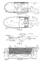
- FIG. 1 With reference to the drawing, and particularly FIG. 1, there is shown a prior art method of dispensing an optical fiber cable 10 wound into a pack 12, the latter being mounted on board a missile 14. More particularly, the fiber cable 10 as it is taken off the pack is ducted along a hollow tube 16 in order to be dispensed from the missile aft end at a point spaced laterally from the rocket or jet motor exhaust 18 a substantial distance. By this arrangement the possibility of the motor exhaust 18 damaging the fiber cable is substantially obviated. However, since the dispensing rate is relatively high, the amount of frictional drag imposed by the tube 16 on the cable is not inconsiderable so that this poses some risk of damage to the cable.
- FIG. 1 shows the orientation of a rocket motor 22 to direct the motor exhaust along an off-axis direction 24 away from the dispensing cable. This is another approach in the prior art to avoid dispensing a fiber cable through the exhaust plume. However, in this case, there is the undesirable result that motor boost efficiency is impaired.
- a missile 26 shown in sectional view has a dispenser 28 of the present invention including generally a filament pack 30 preferably formed from an optical fiber cable 32 which is wound into a cylindrical coil about an axis arranged generally coaxial to the missile longitudinal axis.
- the missile also includes a conventional rocket motor 34 mounted internally of the missile aft end (and within the dispenser 28) for projecting a plume 36 along the missile longitudinal axis and outwardly of the missile open end 38 on launch.
- the fiber 32 will be dispensed in an open helix through the outer edge portions of the plume and directly out the missile open end 38.
- FIG. 3 schematically depicts the dispensing of a fiber cable from a fixed dispenser mounted on a moving vehicle, such as the missile 26.
- the fiber cable forms into a generally helical shape as it leaves the pack 30 rotating to follow the "peel point" from the pack, which peel point must move at a speed equal to the payout rate. That is, the cable in a sense flows along this helical path at a speed equal to the payout rate. More particularly, it can be shown that the instantaneous velocity of a fiber element is the vector sum of the helix rotational velocity and the flow velocity.
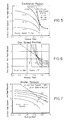
- the dashed line indicates the relative wind for the critical gas speed above which the helix is caused to expand and accelerate.
- the aerodynamic drag damps out the rotation of motion which allows the helix to decay. Because the helix angle decreases as the helix expands, the critical gas velocity decreases with an increase in the helix radius.
- Rocket motor exhaust plumes have a very high speed gas flow along the central axis 40 with gas speed decaying rapidly on moving radially outwardly into the surrounding boundary regions until it reaches what is termed free-stream speed which is the air speed of the vehicle. It is clear from this that a stable fiber helix size may exist at that radius measured from the axis of the motor exhaust plume, where plume velocity equals the critical gas velocity for the helix.
- FIG. 6 is a graph of a certain present day rocket motor depicting a family of gas plume speed versus radius profiles at various distances behind the rocket motor nozzle. Comparison of FIG. 5 showing the critical gas speed curves with the plume gas speed profiles of FIG. 6 shows that filament payout speed must rise to approximately 2,000 feet per second for all rocket motor plume profiles to fall below the critical gas speed boundary.
- This reinforced fiber 42 which is also referred to here as "leader”, consists of a length of the fiber cable 32 encased within a covering which provides both increased tensile strength as well as thermal protection for the enclosed fiber. To reduce the possibility of thermal damage, the leader 42 is dispensed into the rocket plume at a point radially spaced a substantial distance from the plume central axis at which point the temperature is relatively cooler. Also, after the fiber cable develops substantially full dispensing velocity, each fiber element is in the plume only a very short time which significantly reduces the heating effect on the fiber and there is no longer need for the fiber to be reinforced.
- the fiber pack 30 is seen to be wound upon the peripheral surface of a generally cylindrical drum 44 having an integral back wall 46 and front wall 48 between which the pack is wound.
- a cylindrical sidewall 50 is secured to the back wall 46 covering the pack and is spaced from the upper edge of the front wall 48 forming a circular gap or space 52.
- the space 52 is slightly smaller than the leader cross-section so that as the leader is dispensed therethrough frictional contact will occur of a measured amount braking the dispensing speed to less than a predetermined maximum critical value.
- the leader 42 As the leader 42 is dispensed it passes through the outer reaches of the plume 36 in view of its tendency to follow a helical dispensing path. On contact of the leader with the rocket motor plume, the rocket motor gases tend to pull on the leader until full dispensing velocity is achieved. The combined effect of the braking action and the action of the plume gases on the leader dispenses the leader within a desired payout speed which closely approximates the speed of the vehicle, and this is accomplished without the use of expensive and complex apparatus. In addition, it is not necessary to operate the rocket motor in an inefficient manner (i.e., oriented off-axis) in order to prevent or avoid having the leader and fiber pass through the rocket plume as is done in certain existing missiles.
- an inefficient manner i.e., oriented off-axis
Landscapes
- Engineering & Computer Science (AREA)
- General Engineering & Computer Science (AREA)
- Chemical & Material Sciences (AREA)
- Combustion & Propulsion (AREA)
- Physics & Mathematics (AREA)
- Aviation & Aerospace Engineering (AREA)
- General Physics & Mathematics (AREA)
- Optics & Photonics (AREA)
- Aiming, Guidance, Guns With A Light Source, Armor, Camouflage, And Targets (AREA)
- Light Guides In General And Applications Therefor (AREA)
- Tension Adjustment In Filamentary Materials (AREA)
Applications Claiming Priority (2)
| Application Number | Priority Date | Filing Date | Title |
|---|---|---|---|
| US07/649,507 US5143319A (en) | 1991-02-01 | 1991-02-01 | Method and apparatus for dispensing an optical fiber from a powered missile through the motor exhaust |
| US649507 | 1996-05-17 |
Publications (2)
| Publication Number | Publication Date |
|---|---|
| EP0497487A2 true EP0497487A2 (de) | 1992-08-05 |
| EP0497487A3 EP0497487A3 (en) | 1993-06-30 |
Family
ID=24605100
Family Applications (1)
| Application Number | Title | Priority Date | Filing Date |
|---|---|---|---|
| EP19920300510 Withdrawn EP0497487A3 (en) | 1991-02-01 | 1992-01-21 | Method and apparatus for dispensing an optical fiber from a powered missile through the motor exhaust |
Country Status (7)
| Country | Link |
|---|---|
| US (1) | US5143319A (de) |
| EP (1) | EP0497487A3 (de) |
| JP (1) | JPH04340099A (de) |
| AU (1) | AU632009B2 (de) |
| CA (1) | CA2057467A1 (de) |
| IL (1) | IL100525A (de) |
| NO (1) | NO920287L (de) |
Cited By (2)
| Publication number | Priority date | Publication date | Assignee | Title |
|---|---|---|---|---|
| FR2703863A1 (fr) * | 1993-04-06 | 1994-10-14 | Aerospatiale | Bobine de fil de communication entre un aéronef et une station au sol. |
| EP0620461A3 (de) * | 1993-04-14 | 1995-05-17 | Israel State | Durch eine Glasfaser gesteuertes Flugobjekt. |
Families Citing this family (3)
| Publication number | Priority date | Publication date | Assignee | Title |
|---|---|---|---|---|
| US5104057A (en) * | 1989-11-01 | 1992-04-14 | Hughes Aircraft Company | Gas damped filament dispenser |
| WO1996018865A1 (en) * | 1994-12-16 | 1996-06-20 | Sci Systems, Inc. | Fiber-optic cable dispenser and remotely controlled vehicle using same |
| FR3069051B1 (fr) * | 2017-07-12 | 2019-08-16 | Mbda France | Dispositif deflecteur de flux de particules pour projectile guide par un fil de liaison |
Family Cites Families (4)
| Publication number | Priority date | Publication date | Assignee | Title |
|---|---|---|---|---|
| US3233548A (en) * | 1963-11-12 | 1966-02-08 | Canrad Prec Ind Inc | Dirigible aerial torpedo |
| FR1450755A (fr) * | 1965-07-13 | 1966-06-24 | Nord Aviation | Dispositif régulateur pour bobines de câbles électriques de télécommande |
| US4903607A (en) * | 1988-08-02 | 1990-02-27 | Optelecom, Inc. | Communication link winding and dispensing projectile |
| US4974793A (en) * | 1989-12-15 | 1990-12-04 | The Boeing Company | Tapered chamber dispensing of optical fiber |
-
1991
- 1991-02-01 US US07/649,507 patent/US5143319A/en not_active Expired - Lifetime
- 1991-12-11 CA CA002057467A patent/CA2057467A1/en not_active Abandoned
- 1991-12-26 IL IL10052591A patent/IL100525A/en not_active IP Right Cessation
-
1992
- 1992-01-21 EP EP19920300510 patent/EP0497487A3/en not_active Withdrawn
- 1992-01-22 NO NO92920287A patent/NO920287L/no unknown
- 1992-01-27 JP JP4011828A patent/JPH04340099A/ja active Pending
- 1992-01-30 AU AU10645/92A patent/AU632009B2/en not_active Ceased
Cited By (2)
| Publication number | Priority date | Publication date | Assignee | Title |
|---|---|---|---|---|
| FR2703863A1 (fr) * | 1993-04-06 | 1994-10-14 | Aerospatiale | Bobine de fil de communication entre un aéronef et une station au sol. |
| EP0620461A3 (de) * | 1993-04-14 | 1995-05-17 | Israel State | Durch eine Glasfaser gesteuertes Flugobjekt. |
Also Published As
| Publication number | Publication date |
|---|---|
| IL100525A (en) | 1994-11-11 |
| NO920287L (no) | 1992-08-03 |
| US5143319A (en) | 1992-09-01 |
| JPH04340099A (ja) | 1992-11-26 |
| EP0497487A3 (en) | 1993-06-30 |
| NO920287D0 (no) | 1992-01-22 |
| AU1064592A (en) | 1992-08-06 |
| AU632009B2 (en) | 1992-12-10 |
| CA2057467A1 (en) | 1992-08-02 |
| IL100525A0 (en) | 1992-09-06 |
Similar Documents
| Publication | Publication Date | Title |
|---|---|---|
| US6055350A (en) | Method of installing an optical fibre unit in a tube | |
| US4903607A (en) | Communication link winding and dispensing projectile | |
| US5143319A (en) | Method and apparatus for dispensing an optical fiber from a powered missile through the motor exhaust | |
| JPH03102200A (ja) | 回転巻胴フイラメントデイスペンサ | |
| JP2804871B2 (ja) | 接着剤を少なくした内側繰出し光ファイバキャニスタ | |
| US5501411A (en) | Towed vehicle deployment apparatus having guide to reduce line pull-off angle | |
| US5094405A (en) | Mechanically braked towed vehicle deployment device | |
| US5102063A (en) | Aerodynamically braked towed vehicle deployment device | |
| US5678785A (en) | Fiber-optic cable dispenser and remotely controlled vehicle using same | |
| US4974793A (en) | Tapered chamber dispensing of optical fiber | |
| EP0450795B1 (de) | Faseroptisches Abspulsystem für ein in einem offenen Rohr heiss abgefeuertes Projektil | |
| JPH04227496A (ja) | フィラメント繰出装置 | |
| US4653379A (en) | Filament deployment means | |
| US5520346A (en) | Reel payout system | |
| US20030140773A1 (en) | Towed airborne vehicle control and explosion damage assessment | |
| KR100211486B1 (ko) | 인사이드 페이아우트 광섬유 캐니스터를 가진 미사일 | |
| EP0503789B1 (de) | Lineare Abzugsvorrichtung | |
| JPH0653542B2 (ja) | 制動フィラメント繰出し装置 | |
| EP0510819B1 (de) | Gasgedämpfte Abwickelvorrichtung für eine Faser | |
| JP2749413B2 (ja) | 湾曲を制限する堅牢なリーダおよび保持システム | |
| CA2462896C (en) | Method and apparatus for the recovery of bodies towed from moving vehicles | |
| JPH0339900A (ja) | ミサイルのフィラメント配布装置 | |
| AU2002356557A1 (en) | Method and apparatus for the recovery of bodies towed from moving vehicles | |
| US6113027A (en) | Flight launched fiber optic dual payout system | |
| US5031995A (en) | Composite reinforced fiber for high G loads |
Legal Events
| Date | Code | Title | Description |
|---|---|---|---|
| PUAI | Public reference made under article 153(3) epc to a published international application that has entered the european phase |
Free format text: ORIGINAL CODE: 0009012 |
|
| AK | Designated contracting states |
Kind code of ref document: A2 Designated state(s): CH DE ES FR GB IT LI |
|
| PUAL | Search report despatched |
Free format text: ORIGINAL CODE: 0009013 |
|
| AK | Designated contracting states |
Kind code of ref document: A3 Designated state(s): CH DE ES FR GB IT LI |
|
| 17P | Request for examination filed |
Effective date: 19931208 |
|
| 18W | Application withdrawn |
Withdrawal date: 19950608 |